EP2249455A1 - Ladeeinrichtung und qualitätsbeurteilungseinrichtung einer packzelle - Google Patents
Ladeeinrichtung und qualitätsbeurteilungseinrichtung einer packzelle Download PDFInfo
- Publication number
- EP2249455A1 EP2249455A1 EP08721084A EP08721084A EP2249455A1 EP 2249455 A1 EP2249455 A1 EP 2249455A1 EP 08721084 A EP08721084 A EP 08721084A EP 08721084 A EP08721084 A EP 08721084A EP 2249455 A1 EP2249455 A1 EP 2249455A1
- Authority
- EP
- European Patent Office
- Prior art keywords
- voltage value
- cell
- value
- packed battery
- cell voltage
- Prior art date
- Legal status (The legal status is an assumption and is not a legal conclusion. Google has not performed a legal analysis and makes no representation as to the accuracy of the status listed.)
- Withdrawn
Links
Images


Classifications
-
- G—PHYSICS
- G01—MEASURING; TESTING
- G01R—MEASURING ELECTRIC VARIABLES; MEASURING MAGNETIC VARIABLES
- G01R31/00—Arrangements for testing electric properties; Arrangements for locating electric faults; Arrangements for electrical testing characterised by what is being tested not provided for elsewhere
- G01R31/36—Arrangements for testing, measuring or monitoring the electrical condition of accumulators or electric batteries, e.g. capacity or state of charge [SoC]
- G01R31/382—Arrangements for monitoring battery or accumulator variables, e.g. SoC
- G01R31/3842—Arrangements for monitoring battery or accumulator variables, e.g. SoC combining voltage and current measurements
-
- G—PHYSICS
- G01—MEASURING; TESTING
- G01R—MEASURING ELECTRIC VARIABLES; MEASURING MAGNETIC VARIABLES
- G01R31/00—Arrangements for testing electric properties; Arrangements for locating electric faults; Arrangements for electrical testing characterised by what is being tested not provided for elsewhere
- G01R31/36—Arrangements for testing, measuring or monitoring the electrical condition of accumulators or electric batteries, e.g. capacity or state of charge [SoC]
- G01R31/389—Measuring internal impedance, internal conductance or related variables
-
- G—PHYSICS
- G01—MEASURING; TESTING
- G01R—MEASURING ELECTRIC VARIABLES; MEASURING MAGNETIC VARIABLES
- G01R31/00—Arrangements for testing electric properties; Arrangements for locating electric faults; Arrangements for electrical testing characterised by what is being tested not provided for elsewhere
- G01R31/36—Arrangements for testing, measuring or monitoring the electrical condition of accumulators or electric batteries, e.g. capacity or state of charge [SoC]
- G01R31/392—Determining battery ageing or deterioration, e.g. state of health
-
- H—ELECTRICITY
- H01—ELECTRIC ELEMENTS
- H01M—PROCESSES OR MEANS, e.g. BATTERIES, FOR THE DIRECT CONVERSION OF CHEMICAL ENERGY INTO ELECTRICAL ENERGY
- H01M10/00—Secondary cells; Manufacture thereof
- H01M10/42—Methods or arrangements for servicing or maintenance of secondary cells or secondary half-cells
- H01M10/44—Methods for charging or discharging
- H01M10/441—Methods for charging or discharging for several batteries or cells simultaneously or sequentially
-
- H—ELECTRICITY
- H01—ELECTRIC ELEMENTS
- H01M—PROCESSES OR MEANS, e.g. BATTERIES, FOR THE DIRECT CONVERSION OF CHEMICAL ENERGY INTO ELECTRICAL ENERGY
- H01M10/00—Secondary cells; Manufacture thereof
- H01M10/42—Methods or arrangements for servicing or maintenance of secondary cells or secondary half-cells
- H01M10/48—Accumulators combined with arrangements for measuring, testing or indicating the condition of cells, e.g. the level or density of the electrolyte
- H01M10/482—Accumulators combined with arrangements for measuring, testing or indicating the condition of cells, e.g. the level or density of the electrolyte for several batteries or cells simultaneously or sequentially
-
- H—ELECTRICITY
- H02—GENERATION; CONVERSION OR DISTRIBUTION OF ELECTRIC POWER
- H02J—ELECTRIC POWER NETWORKS; CIRCUIT ARRANGEMENTS OR SYSTEMS FOR SUPPLYING OR DISTRIBUTING ELECTRIC POWER; SYSTEMS FOR STORING ELECTRIC ENERGY
- H02J7/00—Circuit arrangements for charging or discharging batteries or for supplying loads from batteries
- H02J7/50—Circuit arrangements for charging or discharging batteries or for supplying loads from batteries acting upon multiple batteries simultaneously or sequentially
-
- H—ELECTRICITY
- H01—ELECTRIC ELEMENTS
- H01M—PROCESSES OR MEANS, e.g. BATTERIES, FOR THE DIRECT CONVERSION OF CHEMICAL ENERGY INTO ELECTRICAL ENERGY
- H01M10/00—Secondary cells; Manufacture thereof
- H01M10/42—Methods or arrangements for servicing or maintenance of secondary cells or secondary half-cells
- H01M10/425—Structural combination with electronic components, e.g. electronic circuits integrated to the outside of the casing
- H01M2010/4271—Battery management systems including electronic circuits, e.g. control of current or voltage to keep battery in healthy state, cell balancing
-
- H—ELECTRICITY
- H02—GENERATION; CONVERSION OR DISTRIBUTION OF ELECTRIC POWER
- H02J—ELECTRIC POWER NETWORKS; CIRCUIT ARRANGEMENTS OR SYSTEMS FOR SUPPLYING OR DISTRIBUTING ELECTRIC POWER; SYSTEMS FOR STORING ELECTRIC ENERGY
- H02J7/00—Circuit arrangements for charging or discharging batteries or for supplying loads from batteries
- H02J7/50—Circuit arrangements for charging or discharging batteries or for supplying loads from batteries acting upon multiple batteries simultaneously or sequentially
- H02J7/52—Circuit arrangements for charging or discharging batteries or for supplying loads from batteries acting upon multiple batteries simultaneously or sequentially for charge balancing, e.g. equalisation of charge between batteries
-
- Y—GENERAL TAGGING OF NEW TECHNOLOGICAL DEVELOPMENTS; GENERAL TAGGING OF CROSS-SECTIONAL TECHNOLOGIES SPANNING OVER SEVERAL SECTIONS OF THE IPC; TECHNICAL SUBJECTS COVERED BY FORMER USPC CROSS-REFERENCE ART COLLECTIONS [XRACs] AND DIGESTS
- Y02—TECHNOLOGIES OR APPLICATIONS FOR MITIGATION OR ADAPTATION AGAINST CLIMATE CHANGE
- Y02E—REDUCTION OF GREENHOUSE GAS [GHG] EMISSIONS, RELATED TO ENERGY GENERATION, TRANSMISSION OR DISTRIBUTION
- Y02E60/00—Enabling technologies; Technologies with a potential or indirect contribution to GHG emissions mitigation
- Y02E60/10—Energy storage using batteries
Definitions
- the present invention relates to an art of a charging apparatus and a quality judging apparatus for a packed battery, especially an art of a charging apparatus and a quality judging apparatus for a packed battery in which a plurality of secondary cells are connected in series.
- a secondary cell such as a nickel-cadmium cell, a nickel-hydrogen cell and a lithium-ion cell, can be used repeatedly by repeating a cycle of charge and discharge.
- the secondary cell is charged several times, because of overcharging, deterioration of electrolyte or electrode plate of the secondary cell, or the like, the charge capacity becomes smaller than that of the initial, whereby the deterioration of the secondary cell progresses and the secondary cell becomes unable of being used finally.
- the main cause of the deterioration of the secondary cell is the overcharging.
- there are well known methods for charging while preventing the overcharging for example, see the Patent Literatures 1 to 4).
- the purpose of the present invention is to provide a charging apparatus and a quality judging apparatus for a packed battery, with which reduction of charging/discharging performance at the time of charging the packed battery can be prevented, reliability of the packed battery can be improved and safety of the packed battery can be secured.
- a charging apparatus for a packed battery charges the packed battery in which a plurality of secondary cells are connected in series, and the charging apparatus comprises: a voltage supply means supplying a predetermined charging voltage to the packed battery; a cell voltage value detection means detecting cell voltage values of the respective secondary cells constituting the packed battery; and a charging control means controlling the charging voltage supplied to the packed battery.
- the charging control means comprises: a dispersion degree calculation means calculating a dispersion degree of the secondary cells based on the cell voltage values detected by the cell voltage value detection means; a maximum value specifying means specifying the maximum value of the cell voltage value based on the dispersion degree calculated by the dispersion degree calculation means; a judging means judging whether or not the maximum value of the cell voltage value specified by the maximum value specifying means reaches a preset permissible cell voltage value; and a charging voltage value change means changing the charging voltage impressed by the voltage supply means based on a voltage difference between the maximum value of the cell voltage value and the permissible cell voltage value when the judging means judges that the maximum value of the cell voltage value is larger than the permissible cell voltage value.
- the cell voltage value detection means includes detecting terminals detecting terminal cell voltage values of the respective secondary cells constituting the packed battery, and the cell voltage value of the secondary cell as a target to be detected is detected based on a potential difference between the terminal cell voltage value of the secondary cell as the target to be detected and the terminal cell voltage value of the secondary cell at the lower potential side of the secondary cell as the target to be detected.
- the charging apparatus for the packed battery further comprises a current value detection means detecting a current value of current flowing in the packed battery.
- the charging control means comprises: a voltage value switch means switching the charging voltage for the packed battery between a predetermined charging voltage value, which exceeds a full-charge balanced voltage value and does not reach an irreversible chemical reaction region, and a check voltage value determined in correspondence to the full-charge balanced voltage value; an internal resistance value calculation means calculating an internal resistance value based on the cell voltage value of the secondary cell detected by the cell voltage value detection means in the case that the predetermined charging voltage value is impressed to the packed battery by the switching of the voltage value switch means, based on the cell voltage value of the secondary cell detected by the cell voltage value detection means in the case that the check voltage value is impressed to the packed battery by the switching of the voltage value switch means, and based on the current value detected by the current value detection means; and a state-of-health calculation means calculating a state of health of the secondary cell based on the cell internal resistance value calculated by the internal resistance value.
- the charging control means has an accumulation amount calculation means calculating a residual accumulation amount of the secondary cell based on the current value detected at the time of the charging, and based on a current value of discharged current.
- a quality judging apparatus for a packed battery judges a quality of the packed battery in which a plurality of secondary cells are connected in series, and comprises: a voltage supply means supplying a predetermined charging voltage to the packed battery; a cell voltage value detection means detecting cell voltage values of the respective secondary cells constituting the packed battery; and a quality judgment means judging a quality of the packed battery.
- the charging control means comprises: a dispersion degree calculation means calculating a dispersion degree of the secondary cells based on the cell voltage values detected by the cell voltage value detection means; a maximum value specifying means specifying the maximum value of the cell voltage value based on the dispersion degree calculated by the dispersion degree calculation means; and a judging means judging whether or not the maximum value of the cell voltage value specified by the maximum value specifying means reaches a preset permissible cell voltage value.
- the cell voltage value detection means includes detecting terminals detecting terminal cell voltage values of the respective secondary cells constituting the packed battery.
- the cell voltage value of the secondary cell as a target to be detected is detected based on a potential difference between the terminal cell voltage value of the secondary cell as the target to be detected and the terminal cell voltage value of the secondary cell at the lower potential side of the secondary cell as the target to be detected.
- the quality judging apparatus for the packed battery further comprises a current value detection means detecting a current value of current flowing in the packed battery.
- the charging control means comprises: a voltage value switch means switched to select whether the packed battery is charged with an external voltage or shut off from the external voltage; an internal resistance value calculation means calculating a cell internal resistance value based on the cell voltage value of the secondary cell detected by the cell voltage value detection means in the case that an external voltage having a predetermined external voltage value is impressed to the packed battery by the switching of the voltage value switch means, based on the cell voltage value of the secondary cell detected by the cell voltage value detection means in the case that the external voltage is isolated from the packed battery by the switching of the voltage value switch means, and based on the current value detected by the current value detection means; and a state-of-health calculation means calculating a state of health of the secondary cell based on the cell internal resistance value calculated by the cell internal resistance value.
- the reduction of charging/discharging performance at the charge of the packed battery is prevented so as to secure reliability and safety of the packed battery. Furthermore, by providing the detecting terminal for each of the secondary cells, the cell voltage value of each secondary cell can be detected easily so that the dispersion of the secondary cells in quality can be judged easily. Furthermore, the charging can be performed without overcharging, and the health degree which is an indicator indicating the progress of deterioration of the secondary cell such as the packed battery in the case that the highest charge voltage is impressed is calculated so that a user can recognize exchange timing of the whole packed battery. Accordingly, sudden defect of the packed battery is prevented so as to improve reliability and safety of the packed battery. Furthermore, by detecting the change of the residual accumulation amount of the packed battery successively from the first, the charge period of the packed battery can be judged easily from the residual accumulation amount.
- the quality judging apparatus of the packed battery in the second aspect of the present invention Due to the quality judging apparatus of the packed battery in the second aspect of the present invention, the reduction of charging/discharging performance at the charge of the packed battery is prevented so as to secure reliability and safety of the packed battery. Furthermore, by providing the detecting terminals for the respective secondary cells, the cell voltage values of the respective secondary cell can be detected easily so that the dispersion of the secondary cells in quality can be judged easily. Furthermore, a user can recognize a timing for exchanging the whole packed battery from the view of the state of health of the secondary cell to which the highest charge voltage is impressed, whereby the reliability and safety of the packed battery is improved.
- the charging apparatus 40 has a voltage supply device 41, a cell voltage value detection device 42, a charging controller 43, a current value detection device 44 and a display device 46.
- the voltage supply device 41 supplies a predetermined charging voltage to the packed battery 10.
- the cell voltage value detection device 42 detects cell voltage values v m of the respective secondary cells 10a constituting the packed battery 10.
- the charging controller 43 controls the charging voltage supplied to the packed battery 10.
- the current value detection device 44 detects a current value J.
- the display device 46 displays an SOH (State Of Health), a residual accumulation amount Q acum and the like.
- SOH State Of Health
- the SOH is an indicator which indicates the progress of deterioration of a secondary cell that may be provided in the packed battery 10, for example, and the SOH is generally defined as a ratio of "actual accumulation capacity" to "initial accumulation capacity". Since the product of the accumulation capacity and internal resistance is constant, the indicator is defined in the present application as an inverse ratio of "actual internal resistance value of the secondary cell" to "initial internal resistance value”.
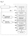
- the charging controller 43 has a storage unit 50, a voltage value switch unit 45, an increment unit 51, a first judging unit 52, a second judging unit 53, a dispersion degree calculation unit 61, a maximum value specifying unit 62, a third judging unit 63, a charging voltage value change unit 64, an internal resistance value calculation unit 65, a state-of-health (SOH) calculation unit 66 and a residual accumulation amount calculation unit 67.
- the charging controller 43 includes a CPU performing various processes, a memory in which programs and the like are stored, and the like.
- the storage unit 50 stores therein a minimum value of check voltage value E c , which is smaller than a full-charge balanced voltage value E eq , a predetermined charging voltage value E a , which is larger than the full-charge balanced voltage value E eq and is smaller than an irreversible chemical reaction region, and a voltage value ⁇ E defining a predetermined increment.
- the voltage value switch unit 45 switches the charging voltage applied to the packed battery 10 between the predetermined charging voltage value E a , which is larger than the full-charge balanced potential value E eq and smaller than the irreversible chemical reaction region, and the check voltage value E c ,which is determined in correspondence to the full-charge balanced potential value E eq .
- the increment unit 51 adds the voltage value ⁇ E of the predetermined increment to the check voltage value E c of the previously impressed check voltage so as to set a new check voltage value E c , and the first judging unit 52 judges whether or not the current value J detected by the current value J detection device 44 becomes not more than a previously inputted criterion value J c .
- the second judging unit 53 judges whether or not the time between the last affirmative judgment by the first judging unit 52 and the present affirmative judgment by the first judging unit 52 is longer than r-times (r is a real number not less than 1) as long as the time between the second last affirmative judgment and the last affirmative judgment.
- the dispersion degree calculation unit 61 calculates a dispersion degree ⁇ of the secondary cells 10a based on the respective cell voltage values v m detected by the cell voltage value detection device 42.
- the dispersion degree ⁇ expresses a dispersion of the secondary cells 10a in quality calculated based on the voltage values thereof.
- the maximum value specifying unit 62 specifies a maximum charge-on cell voltage value v maxon , which is a maximum of a charge-on cell voltage value v mon that is a cell voltage value during impression of the charging voltage, based on the dispersion degree ⁇ of the secondary cells calculated by the dispersion degree calculation unit 61.
- the third judging unit 63 judges whether or not the maximum charge-on cell voltage value v maxon specified by the maximum value specifying unit 62 is larger than a preset permissible cell voltage value v c .
- the charging voltage value change unit 64 changes the charging voltage value E a of the charging voltage impressed by the voltage supply device 41 based on the voltage difference between the maximum charge-on cell voltage value v maxon and the permissible cell voltage value v c when the third judging unit 63 judges that the maximum charge-on cell voltage value v maxon is larger than the permissible cell voltage value v c .
- the internal resistance value calculation unit 65 calculates a cell internal resistance value R m of the secondary cell 10a based on the charge-on cell voltage value v mon of the secondary cell 10a detected by the cell voltage value detection device 42 in the case that the charging voltage is impressed at the charging voltage value E a to the packed battery 10 by the switching of the voltage value switch unit 45, based on a closed-circuit cell voltage value v moff of the secondary cell 10a detected by the cell voltage value detection device 42 in the case that a closed circuit is activated to impress the check voltage at the check voltage value E c to the packed battery 10 by the switching of the voltage value switch unit 45, and based on the current value J detected by the current value detection device 44.
- the state-of-health calculation unit 66 calculates a cell state of health SOH m of the most deteriorated secondary cell 10M which indicates the maximum charge-on cell voltage value v maxon at the maximum value specifying unit 62, and calculates the cell state of health SOH m of the most deteriorated secondary cell 10M based on the cell internal resistance value R m of the most deteriorated secondary cell 10M calculated by the internal resistance value calculation unit 65.
- the residual accumulation amount calculation unit 67 calculates the residual accumulation amount Q acum of the secondary cell 10a based on the current value J detected at the time of the accumulation, and based on a discharged current value J out detected at the time of the electric discharge.
- the charging controller 43 controls the accumulation of the packed battery 10 according to below steps. Firstly, as shown in Fig. 3 , the check voltage having the minimum value of check voltage value E c is impressed to the packed battery 10 for a very short time T 2 (step S10), and for the very short time T 2 , the current value J of current flowing in the packed battery 10 is detected by the current value detection device 44 (step S20).
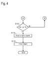
- the detected current value J is judged by the first judging unit 52 (step S30), and when the current value J is larger than the criterion value J c , the value of charging voltage is switched to the predetermined charging voltage value E a by the voltage value switch unit 45, so that the predetermined charging voltage value E a is impressed to the packed battery 10 for a predetermined time T 1 (step S40). Subsequently, the voltage of charging voltage is switched to the minimum value of check voltage value E c by the voltage value switch unit 45, and the control is returned to the step S10.
- the voltage value ⁇ E of the predetermined increment is added to the check voltage value E c of the previously impressed check voltage by the increment unit 51 so as to set a new check voltage value E c (step S50).
- the value of charging voltage is switched to the predetermined charging voltage value E a by the voltage value switch unit 45, and the charging voltage having the predetermined charging voltage value E a is impressed to the packed battery 10 for the predetermined time T 1 (step S60).
- the charging voltage control is performed based on the cell charging voltage values (step S65).
- the voltage of charging voltage is switched to the new check voltage value E c by the voltage value switch unit 45, and the check voltage having the new check voltage value E c is impressed to the packed battery 10 for the very short time T 2 (step S70).
- the cell state of health SOH m of the most deteriorated secondary cell 10M is calculated based on the cell internal resistance value R m of the most deteriorated secondary cell 10M (step S75).
- step S90 the detected current value J is judged by the first judging unit 52 (step S90).
- the control is returned to the step S10.
- the control is shifted to next step S100.
- the time between the last affirmative judgment and the present affirmative judgment by the first judging unit 52 is judged by the second judging unit 53.
- the time N e between the last affirmative judgment and the present affirmative judgment and the present affirmative judgment by the first judging unit 52 is not longer than r-times as long as the time N e-1 between the second last affirmative judgment and the last affirmative judgment, control is returned to the step S50 (see Fig 3 ).
- a charge stop signal is outputted (step S110) and the charge of the packed battery 10 is stopped (step S120).
- any packed battery 10 can be charged so as to seek the full-charge balanced voltage value E eq of the packed battery 10 for making the charging rate reach almost 100%. Even if a part of the internal structure of the packed battery 10 is broken and deteriorated, that is, even if any one of the secondary cells 10a constituting the packed battery 10 is broken, the device is effective so as to seek the actual full-charge balanced voltage value E eq of the packed battery 10 and to charge the battery in consideration of the actual charge capacity, thereby making the charging rate reach almost 100%.
- step S210 charge-on terminal cell voltage values V mon of the respective secondary cells 10a constituting the packed battery 10 are detected as the respective charge-on cell voltage values v mon (step S210). Explanation will be given on a method for detecting the cell voltage value of each of the secondary cells 10a constituting the packed battery 10. As shown in Fig. 2 , the cell voltage value detection device 42 in the embodiment detecting terminals 42a which detect the respective charge-on cell voltage values v mon of the respective secondary cells 10a constituting the packed battery 10.
- a charge-on terminal cell voltage value V 1on of one secondary cell 10a, a charge-on terminal cell voltage value V 2on of two secondary cells 10a, ... and a charge-on terminal cell voltage value V mon of m-pieces ("m" is a real number which is not less than 1 and not more than N) of secondary cells 10a can be detected.
- the charge-on terminal cell voltage value V mon is calculated with Formula 1.
- V mon V mon - V m - 1 ⁇ on
- the charge-on terminal cell voltage value V mon of the (m-count) secondary cell 10a serving as a detection target based on a potential difference between the charge-on terminal cell voltage value V mon of the (m-count) secondary cell 10a serving as a detection target and the charge-on terminal cell voltage value V (m-1)on of the secondary cell 10a, which is disposed at the lower potential side of the secondary cell 10a serving as the detection target, the charge-on cell voltage value v mon of the (m-count) secondary cell 10a as the detection target is detected. Accordingly, the charge-on cell voltage value v mon of each secondary cell 10a can be detected easily so that the dispersion of the secondary cells 10a in quality can be judged easily.
- V Son the full charge-on terminal cell voltage value V Son is calculated with Formula 2.
- the dispersion degree ⁇ and a dispersion exponent dev m are calculated based on the charge-on cell voltage values v mon of the respective secondary cells 10a and an average charge-on voltage value V MEANon of the secondary cells 10a (step S220).
- the average charge-on voltage value V MEANon of the secondary cells 10a is calculated with Formula 3.
- V MEANon V Son / N
- the dispersion degree ⁇ of the charge-on cell voltage values v mon of the respective secondary cells 10a is calculated with Formula 4.
- the dispersion exponent dev m is calculated with Formula 5 from the dispersion degree ⁇ , the average charge-on voltage value V MEANon and the charge-on cell voltage value v mon of the respective secondary cell 10a.
- the dispersion exponent dev m indicates a dispersion of each of the secondary cells 10a in quality.
- the maximum value of the cell voltage value is specified from the dispersion exponent dev m calculated at the step S220 by the maximum value specifying unit 62 based on the dispersion degree ⁇ of the secondary cells 10a calculated by the dispersion degree calculation unit 61 (step S230).
- the dispersion exponents dev m of the respective secondary cells 10a calculated at the step S220 are compared with one another so as to specify the maximum charge-on cell voltage value v maxon which brings the maximum dispersion exponent dev m .
- the most deteriorated secondary cell 10M indicating the maximum charge-on cell voltage value v maxon is the secondary cell 10a whose cell internal resistance value R m is different from those of the other secondary cells 10a, that is, the most deteriorated secondary cell 10M is very possible to be deteriorated and to cause overcharge.
- the third judging unit 63 judges whether or not the maximum charge-on cell voltage value v maxon specified by the maximum value specifying unit 62 is larger than the permissible cell voltage value v c (step S240).
- the charging voltage value change unit 264 changes the predetermined charging voltage value E a of charging voltage impressed by the voltage supply device 41 based on the voltage difference between the maximum charge-on cell voltage value v maxon and the permissible cell voltage value v c , so as to reduce the full charge-on cell voltage value V Son according to Formula 6 (step S250).
- V Son V Son - V maxon - V c
- the charging voltage control based on the cell voltage values is finished.
- the permissible cell voltage value v c is prescribed about each of kinds of secondary cells.
- the permissible cell voltage value v c of a lithium-ion battery is prescribed to be 4.2V.
- step S310 the closed-circuit cell voltage value v moff and the current value J are detected (step S310).
- the closed-circuit cell voltage value is calculated from closed-circuit terminal cell voltage values V moff and V (m-1)off with Formula 3.
- the current value J is detected by the current value detection device 44.
- the cell internal resistance value R m is calculated by the internal resistance value calculation unit 65 (step S320).
- the cell internal resistance value R m is calculated with Formula 7.
- the secondary cell 10a serving as a target of calculation of the cell internal resistance value R m is the most deteriorated secondary cell 10M indicating the maximum dispersion exponent dev m .
- any of the secondary cells 10a may be optionally employed as the target.
- an initial cell internal resistance value R mint is calculated.
- ⁇ v m is the voltage difference between the charge-on cell voltage value v mon of each secondary cell 10a and the closed-circuit cell voltage value v moff of each secondary cell 10a, and is calculated with Formula 8.
- the cell state of health SOH m serving as an indicator which indicates the progress of deterioration of the secondary cell 10a is calculated by the SOH calculation unit 66 (step S330).
- the cell state of health SOH m is an indicator which indicates the progress of deterioration of the secondary cell 10a, and is defined as a ratio of the present charge capacity to the initial charge capacity. Since the product of the charge capacity and the internal resistance is constant, the cell state of health SOH m is defined as an inverse ratio of the cell internal resistance value R m to an initial cell internal resistance value R mint , and can be calculated with Formula 9.
- the cell state of health SOH m can be calculated from the cell internal resistance value R m .
- the initial cell internal resistance value R mint is substituted for the cell internal resistance value R m , so that the cell state of health SOH m is 100.
- step S340 the cell state of health SOH calculated at the step S330 is displayed by the display device 46 (step S340).
- the cell internal resistance value R m of each secondary cell 10a is substantially constant until the closing period of charge. At the closing period of charge, the cell internal resistance value R m generally becomes larger following irreversible chemical reaction of the secondary cell. Therefore, when the charge rate is about 70% at the most, the cell internal resistance value R m of each secondary cell 10a can be calculated accurately.
- the cell internal resistance value R m is calculated from the charge-on cell voltage value v mon , the closed-circuit cell voltage value v moff and the current value J.
- a full charge-on voltage value V Son , a full closed-circuit voltage value V Soff and the current value J may be substituted for corresponding algebras of Formulas 7 and 8 so as to calculate a internal resistance value R of the whole packed battery 10, or the internal resistance value R and an initial internal resistance value R int may be substituted for corresponding algebras of Formula 9 so as to calculate a state of health SOH of the whole packed battery 10.
- the current value J detected at the step S210 is time-integrated by the residual accumulation amount calculation unit 67 so as to calculate the residual accumulation amount Q acum of the packed battery 10 (step S350).
- the residual accumulation amount Q acum is equal to an integrated value Q charge of time integration of the current value J of the packed battery 10.
- the residual accumulation amount Q acum calculated at the step S350 is displayed by the display device 46 (step S360).
- the most deteriorated secondary cell 10M to which the most part of the charging voltage having the predetermined charging voltage value E a is impressed is specified from all the secondary cells 10a constituting the packed battery 10, and the charge of the packed battery 10 can be performed while the predetermined charging voltage value E a of the part of charging voltage impressed to the most deteriorated secondary cell 10M is maintained to be not more than a certain value.
- the respective charge-on cell voltage values v mon of the secondary cells 10a but the full charge-on voltage value V Son of the packed battery 10 is controlled, whereby the charging/discharging ability of the packed battery 10 to be charged is prevented from being reduced, thereby securing reliability and safety of the packed battery 10.
- the charge control is made easy so that production cost is reduced.
- the degree of deterioration of any one of the secondary cells 10a constituting the packed battery 10 can be found from time-dependent change of the cell internal resistance value R m so that a user can recognize a timing for exchanging the whole packed battery 10. Accordingly, the packed battery 10 is prevented from suddenly breaking down, thereby improving reliability and safety of the packed battery 10. Namely, in the case that the cell state of health SOH m is low, when the SOH of the whole packed battery 10 is high, it is very possible that only the most deteriorated secondary cell 10M indicating the low cell state of health SOH m is deteriorated. On the contrary, when the SOH of the whole packed battery 10 is low, it is very possible that the packed battery 10 is entirely deteriorated.
- the period for charging the packed battery 10 can be judged easily from the residual accumulation amount Q acum .
- the charging apparatus 40 of the present embodiment may be adapted to an electric car equipped with a charging equipment, for example, which serves as an apparatus reservably set with the packed battery 10.
- a charging equipment for example, which serves as an apparatus reservably set with the packed battery 10.
- the change of the residual accumulation amount Q acum of the packed battery 10 can be detected successively from the original state.
- the checker 200 includes a voltage supply device 241, a cell voltage value detection device 242, a quality judgment device 243, a current value detection device 244 and a display device 246.
- the voltage supply device 241 supplies a predetermined external voltage to the packed battery 10.
- the voltage value detection device 242, the current value detection device 244 and the display device 246 are respectively constructed similarly to the voltage value detection device 42, the current value detection device 44 and the display device 46 in the above-mentioned embodiment (see Fig. 1 ), and therefore, detailed explanation thereof is omitted.
- the quality judgment device 243 judges the quality of the packed battery 10 and includes a CPU performing various processes, a memory in which program and the like are stored, and the like.
- the quality judgment device 243 includes a storage unit 250, a voltage value switch unit 245, a dispersion degree calculation unit 261, a maximum value specifying unit 262, an internal resistance value calculation unit 265 and a state-of-health (SOH) calculation unit 266.
- the storage unit 250 stores therein the permissible cell voltage value v c of the secondary cell 10a.
- the voltage value switch unit 245 is switched to select whether the packed battery 10 is charged with the external voltage or is shut off from the external voltage.
- the dispersion degree calculation unit 261, the maximum value specifying unit 262, the internal resistance value calculation unit 265 and the state-of-health calculation unit 266 are respectively constructed similarly to the dispersion degree calculation unit 61, the maximum value specifying unit 62, the internal resistance value calculation unit 65 and the state-of-health calculation unit 66 in the above-mentioned embodiment (see Fig. 1 ), and therefore, detailed explanation thereof is omitted.
- the voltage value switch unit 245 is turned “ON” so that the external voltage is impressed by the voltage supply device 241 and the quality judgment is performed based on the cell voltage values (step S510). Then, the voltage value switch unit 245 is turned “OFF” so as to shut off the external voltage, and the cell state of health SOH m of the most deteriorated secondary cell 10M is calculated from the cell internal resistance value R m of the most deteriorated secondary cell 10M (step S520).
- the quality judgment based on the cell voltage value is performed with below steps.
- the charge-on cell voltage value v mon is detected from the charge-on terminal cell voltage value V mon of each of the secondary cells 10a (step S610).
- the method for detecting the cell voltage values of the respective secondary cells 10a constituting the packed battery 10 in this case is similar to the method for detecting the cell voltage values according to the above-mentioned embodiment (see Fig. 5 ).
- the charge-on cell voltage value v mon of each secondary cell 10a is detected with Formula 1 and the full charge-on voltage value V Son of the packed battery 10 is calculated with Formula 2.
- the dispersion degree calculation unit 261 calculates the dispersion degree ⁇ and the dispersion exponent dev m from the charge-on cell voltage value v mon and the average charge-on voltage value V MEANon of each secondary cell 10a.
- the calculation methods of the average charge-on voltage value V MEANon , the dispersion degree ⁇ and the dispersion exponent dev m in this case are similar to the calculation method of the above-mentioned embodiment (see Fig. 5 ).
- the average charge-on voltage value V MEANon , the dispersion degree ⁇ and the dispersion exponent dev m are calculated respectively with Formulas 3, 4 and 5.
- the maximum value specifying unit 262 based on the dispersion degree ⁇ of the secondary cell 10a calculated by the dispersion degree calculation unit 261, the maximum of the cell voltage value is specified from the dispersion exponent dev m calculated at the step S620 (step S630).
- the dispersion exponent dev m of each secondary cell 10a calculated at the step S620 is compared with each other so as to specify the maximum charge-on cell voltage value v maxon of the most deteriorated secondary cell 10M indicating the maximum dispersion exponent dev m .
- the most deteriorated secondary cell 10M indicating the maximum charge-on cell voltage value v maxon is the secondary cell 10a whose cell internal resistance value R m is different from those of the other secondary cells 10a, that is, the most deteriorated secondary cell 10M is very possible to be deteriorated and to cause overcharge.
- the fourth judging unit 263 judges whether or not the maximum charge-on cell voltage value v maxon specified by the maximum value specifying unit 262 is larger than the preset permissible cell voltage value v c (step S640).
- the maximum charge-on cell voltage value v maxon When the maximum charge-on cell voltage value v maxon is judged to be larger than the permissible cell voltage value v c , the maximum charge-on cell voltage value v maxon of the most deteriorated secondary cell 10M is displayed by the display device 246 (step S650). At this time, the display device 246 may display a warning of the deterioration of the secondary cell 10a for user's notice in addition to the display of the maximum charge-on cell voltage value v maxon . Subsequently, the quality judgment based on the cell voltage values is finished. When the maximum charge-on cell voltage value v maxon is judged to be not more than the permissible cell voltage value v c , the quality judgment based on the cell voltage value is finished.
- the cell state of health SOH m of the most deteriorated secondary cell 10M is calculated from the cell internal resistance value R m of the most deteriorated secondary cell 10M (step S520).
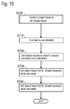
- the calculation of the cell state of health SOH m of the most deteriorated secondary cell 10M is performed with below steps. Firstly, as shown in Fig. 10 , the shut-off cell voltage value v mshut and the current value J are detected (step S710).
- the shut-off cell voltage value v mshut is calculated with formula 1 from shut-off terminal cell voltage values V mshut and V (m-1) shut .
- the current value J is detected by the current value detection device 44.
- the cell internal resistance value R m is calculated (step S720).
- the cell internal resistance value R m is calculated with Formula 7 by the same calculation method as the above-mentioned embodiment (see Fig. 6 ).
- the secondary cell 10a as a target of calculation of the cell internal resistance value R m is the most deteriorated secondary cell 10M indicating the maximum dispersion exponent dev m . Instead of the most deteriorated secondary cell 10M, any of the secondary cells 10a may be optionally employed as the target.
- the initial cell internal resistance value R mint is calculated with Formula 7.
- ⁇ v m in Formula 7 is the voltage difference between the charge-on cell voltage value v mon of each secondary cell 10a and the shut-off cell voltage value v mshut of each secondary cell 10a, and is calculated with Formula 10.
- the cell state of health SOH m serving as an indicator which indicates the progress of deterioration of the secondary cell 10a is calculated by the state-of-health calculation unit 266 (step S730).
- the cell state of health SOH m is an indicator which indicates the progress of deterioration of the secondary cell 10a, and is defined as a ratio of the present charge capacity to the initial charge capacity. Since the product of the charge capacity and the internal resistance is constant, the cell state of health SOH m is defined as an inverse ratio of the cell internal resistance value R m to the initial cell internal resistance value R mint , and can be calculated with Formula 9.
- the cell internal resistance value R m is calculated from the charge-on cell voltage value v mon , the shut-off cell voltage value v mshut and the current value J.
- the full charge-on voltage value V Son , the full shut-off voltage value V Sshut and the current value J may be substituted for corresponding algebras of Formulas 7 and 10 so as to calculate the internal resistance value R of the whole packed battery 10, or the internal resistance value R and the initial internal resistance value R int may be substituted for corresponding algebras of Formula 9 so as to calculate the state of health SOH of the whole packed battery 10.
- step S740 the cell state of health SOH m is displayed by the display device 246 (step S740). Subsequently, the calculation of the cell state of health SOH m of the most deteriorated secondary cell 10M is finished.
- the checker 200 in the present embodiment is constructed so as to judge whether or not the maximum charge-on cell voltage value v maxon larger than the permissible cell voltage value v c exists in the secondary cells 10a constituting the packed battery 10. Accordingly, the charging/discharging ability of the packed battery 10 to be charged is prevented from being reduced, thereby securing reliability and safety of the packed battery 10.
- the dispersion degree ⁇ and the maximum charge-on cell voltage value v maxon can lead to judge whether the packed battery 10 is entirely deteriorated or any of the secondary cells 10a is deteriorated.
- a user can recognize a timing for exchanging the whole packed battery 10 from the state of health of the whole packed battery 10. Accordingly, the packed battery 10 is prevented from suddenly breaking down, thereby improving reliability and safety of the packed battery 10.
- the charging apparatus and quality judging apparatus of packed battery according to the present invention can be employed suitably for a charging apparatus which charges a packed battery in which a plurality of secondary cells are connected in series.
Landscapes
- Engineering & Computer Science (AREA)
- Manufacturing & Machinery (AREA)
- Chemical & Material Sciences (AREA)
- Chemical Kinetics & Catalysis (AREA)
- Electrochemistry (AREA)
- General Chemical & Material Sciences (AREA)
- Power Engineering (AREA)
- Physics & Mathematics (AREA)
- General Physics & Mathematics (AREA)
- Secondary Cells (AREA)
- Charge And Discharge Circuits For Batteries Or The Like (AREA)
Applications Claiming Priority (1)
| Application Number | Priority Date | Filing Date | Title |
|---|---|---|---|
| PCT/JP2008/053664 WO2009107236A1 (ja) | 2008-02-29 | 2008-02-29 | パック電池の充電装置及びパック電池の品質判定装置 |
Publications (1)
| Publication Number | Publication Date |
|---|---|
| EP2249455A1 true EP2249455A1 (de) | 2010-11-10 |
Family
ID=41015649
Family Applications (1)
| Application Number | Title | Priority Date | Filing Date |
|---|---|---|---|
| EP08721084A Withdrawn EP2249455A1 (de) | 2008-02-29 | 2008-02-29 | Ladeeinrichtung und qualitätsbeurteilungseinrichtung einer packzelle |
Country Status (5)
| Country | Link |
|---|---|
| US (1) | US20100327809A1 (de) |
| EP (1) | EP2249455A1 (de) |
| KR (1) | KR20100114123A (de) |
| CN (1) | CN101960691B (de) |
| WO (1) | WO2009107236A1 (de) |
Families Citing this family (13)
| Publication number | Priority date | Publication date | Assignee | Title |
|---|---|---|---|---|
| US8111037B2 (en) * | 2008-06-27 | 2012-02-07 | GM Global Technology Operations LLC | Method for battery state-of-health monitoring using battery voltage during vehicle starting |
| US8841289B2 (en) | 2009-10-13 | 2014-09-23 | Merck Sharp & Dohme B.V. | Heterocyclic derivatives |
| US20120119749A1 (en) * | 2010-03-26 | 2012-05-17 | Takuma Iida | Charge state detection circuit, battery power supply device, and battery information monitoring device |
| JP5299397B2 (ja) * | 2010-10-18 | 2013-09-25 | 株式会社デンソー | 電池状態監視装置 |
| KR101293630B1 (ko) * | 2011-04-25 | 2013-08-05 | 주식회사 엘지화학 | 배터리 용량 퇴화 추정 장치 및 방법 |
| CN103492893B (zh) * | 2011-04-25 | 2015-09-09 | 株式会社Lg化学 | 用于估计电池容量的劣化的设备和方法 |
| KR20130025668A (ko) * | 2011-09-02 | 2013-03-12 | 삼성전기주식회사 | 패드형 전극 접점 충전 장치 |
| CN102520366B (zh) * | 2011-12-23 | 2014-11-12 | 上海交通大学 | 电动车电池安全与健康评估系统及其方法 |
| JP6237244B2 (ja) * | 2014-01-14 | 2017-11-29 | 株式会社ジェイテクト | 蓄電デバイスにおける蓄電材料の粒子の分散度合検査装置 |
| US10663529B1 (en) | 2015-09-25 | 2020-05-26 | Amazon Technologies, Inc. | Automatic battery charging |
| CN105223514B (zh) * | 2015-10-14 | 2018-04-27 | 中国南方电网有限责任公司调峰调频发电公司 | 大容量储能设备的可靠性判断方法 |
| US11688889B2 (en) * | 2021-11-10 | 2023-06-27 | Beta Air, Llc | Monitoring system and method for charging multiple battery packs in an electric aircraft |
| US12494657B2 (en) | 2023-09-06 | 2025-12-09 | Ford Global Technologies, Llc | Systems and methods for battery cell degradation detection |
Family Cites Families (17)
| Publication number | Priority date | Publication date | Assignee | Title |
|---|---|---|---|---|
| DE69033939T2 (de) * | 1989-12-11 | 2002-09-12 | Canon K.K., Tokio/Tokyo | Ladegerät |
| JPH05336674A (ja) * | 1992-05-28 | 1993-12-17 | Toshiba Battery Co Ltd | 二次電池の充電回路 |
| JPH06133465A (ja) * | 1992-08-27 | 1994-05-13 | Sanyo Electric Co Ltd | 二次電池の充電方法及び充電装置 |
| JP3157686B2 (ja) * | 1994-11-08 | 2001-04-16 | 松下電器産業株式会社 | 組電池の充電制御装置 |
| JP3539123B2 (ja) | 1997-03-24 | 2004-07-07 | 日本電信電話株式会社 | 二次電池の劣化判定方法およびその装置 |
| JP3913443B2 (ja) | 2000-04-27 | 2007-05-09 | 三洋電機株式会社 | パック電池の劣化検出方法 |
| JP3681624B2 (ja) * | 2000-08-31 | 2005-08-10 | 富士通株式会社 | 充電回路、充放電回路、及び電池パック |
| JP3430439B2 (ja) | 2000-12-22 | 2003-07-28 | 財団法人新産業創造研究機構 | 二次電池の充電方法及び二次電池の充電装置 |
| JP3979831B2 (ja) * | 2001-12-05 | 2007-09-19 | 三洋電機株式会社 | 二次電池装置 |
| CN1165103C (zh) * | 2002-01-07 | 2004-09-01 | 北京航空航天大学 | 一种串联电池组自动均衡充电装置 |
| JP3867581B2 (ja) * | 2002-01-17 | 2007-01-10 | 松下電器産業株式会社 | 組電池システム |
| CN100367627C (zh) * | 2002-05-17 | 2008-02-06 | 核心技术国际有限公司 | 充电电池的充电装置及充电方法 |
| JP3752249B2 (ja) | 2004-02-25 | 2006-03-08 | テクノコアインターナショナル株式会社 | 二次電池の充電装置 |
| US7345453B2 (en) * | 2005-03-01 | 2008-03-18 | Honeywell International, Inc. | Capacity degredation in a lead acid battery method and apparatus |
| JP2007318950A (ja) * | 2006-05-27 | 2007-12-06 | Gs Yuasa Corporation:Kk | 二次電池のセル電圧バランス装置 |
| JP4872496B2 (ja) * | 2006-07-06 | 2012-02-08 | 日産自動車株式会社 | 組電池のバラツキ検知装置 |
| JP4802945B2 (ja) * | 2006-08-31 | 2011-10-26 | トヨタ自動車株式会社 | 二次電池の制御システムおよびそれを搭載したハイブリッド車両 |
-
2008
- 2008-02-29 CN CN2008801276168A patent/CN101960691B/zh not_active Expired - Fee Related
- 2008-02-29 US US12/918,735 patent/US20100327809A1/en not_active Abandoned
- 2008-02-29 EP EP08721084A patent/EP2249455A1/de not_active Withdrawn
- 2008-02-29 KR KR1020107019896A patent/KR20100114123A/ko not_active Withdrawn
- 2008-02-29 WO PCT/JP2008/053664 patent/WO2009107236A1/ja not_active Ceased
Non-Patent Citations (1)
| Title |
|---|
| See references of WO2009107236A1 * |
Also Published As
| Publication number | Publication date |
|---|---|
| CN101960691A (zh) | 2011-01-26 |
| CN101960691B (zh) | 2013-04-24 |
| WO2009107236A1 (ja) | 2009-09-03 |
| US20100327809A1 (en) | 2010-12-30 |
| KR20100114123A (ko) | 2010-10-22 |
Similar Documents
| Publication | Publication Date | Title |
|---|---|---|
| EP2249455A1 (de) | Ladeeinrichtung und qualitätsbeurteilungseinrichtung einer packzelle | |
| EP3958006B1 (de) | Batteriediagnosevorrichtung und -verfahren | |
| EP3961233B1 (de) | Vorrichtung und verfahren zur diagnose von batteriezellen | |
| US9541608B2 (en) | Apparatus and method for measuring insulation resistance of battery | |
| EP3719917B1 (de) | Vorrichtung zur detektion von anomalien bei einer aufladbaren zelle und verfahren zur detektion von anomalien bei einer aufladbaren zelle | |
| KR101989491B1 (ko) | 언노운 방전 전류에 의한 배터리 셀의 불량 검출 장치 및 방법 | |
| US9219377B2 (en) | Battery charging apparatus and battery charging method | |
| EP4130767A1 (de) | Verfahren und vorrichtung zur erkennung von lithiumplattierung sowie verfahren und vorrichtung zur erfassung des polarisationsanteils | |
| EP2838152B1 (de) | Entladevorrichtung für stromspeichervorrichtung | |
| KR102717091B1 (ko) | 배터리 관리 장치, 배터리 팩, 에너지 저장 시스템 및 배터리 관리 방법 | |
| EP2728368B1 (de) | Zustandsschätzungsvorrichtung und Verfahren für Batterie | |
| US10218036B2 (en) | Battery pack, electrical device, and control method therefor | |
| US20090112496A1 (en) | Battery pack, method of charging secondary battery and battery charger | |
| EP3141919B1 (de) | Vorrichtung und verfahren zur schätzung von leerlaufspannung | |
| US20060186859A1 (en) | Internal short detection apparatus for secondary-battery, internal short detection method for secondary-battery, battery-pack, and electronic equipment | |
| EP3832331B1 (de) | Zellzustandschätzungsvorrichtung und zellsteuerungsvorrichtung | |
| CN111108403A (zh) | 可充电电池短路预测装置和可充电电池短路预测方法 | |
| KR20100002151A (ko) | 전지 팩 및 제어 방법 | |
| KR101572650B1 (ko) | 배터리 뱅크의 불균형 진단 장치 및 방법 | |
| EP1835297B1 (de) | Verfahren und Vorrichtung zur Bestimmung der Eigenschaften einer unbekannten Batterie | |
| EP3323665B1 (de) | Batteriepackausgleichssystem und -verfahren | |
| JP2002162451A (ja) | リチウムイオン電池の容量推定方法、劣化判定方法および劣化判定装置ならびに劣化判定機能を具備したリチウムイオン電池パック | |
| JP3649643B2 (ja) | リチウムイオン電池の容量推定方法 | |
| JP6779808B2 (ja) | 二次電池の劣化判定方法及び二次電池の劣化判定装置 | |
| JP2009207332A (ja) | パック電池の充電装置及びパック電池の品質判定装置 |
Legal Events
| Date | Code | Title | Description |
|---|---|---|---|
| PUAI | Public reference made under article 153(3) epc to a published international application that has entered the european phase |
Free format text: ORIGINAL CODE: 0009012 |
|
| 17P | Request for examination filed |
Effective date: 20100825 |
|
| AK | Designated contracting states |
Kind code of ref document: A1 Designated state(s): AT BE BG CH CY CZ DE DK EE ES FI FR GB GR HR HU IE IS IT LI LT LU LV MC MT NL NO PL PT RO SE SI SK TR |
|
| AX | Request for extension of the european patent |
Extension state: AL BA MK RS |
|
| DAX | Request for extension of the european patent (deleted) | ||
| STAA | Information on the status of an ep patent application or granted ep patent |
Free format text: STATUS: THE APPLICATION IS DEEMED TO BE WITHDRAWN |
|
| 18D | Application deemed to be withdrawn |
Effective date: 20120901 |