EP2249459A1 - Tension d'alimentation pour une unité de commande d'un circuit d'éclairage de secours - Google Patents
Tension d'alimentation pour une unité de commande d'un circuit d'éclairage de secours Download PDFInfo
- Publication number
- EP2249459A1 EP2249459A1 EP20100168831 EP10168831A EP2249459A1 EP 2249459 A1 EP2249459 A1 EP 2249459A1 EP 20100168831 EP20100168831 EP 20100168831 EP 10168831 A EP10168831 A EP 10168831A EP 2249459 A1 EP2249459 A1 EP 2249459A1
- Authority
- EP
- European Patent Office
- Prior art keywords
- control unit
- battery
- circuit
- switch
- voltage
- Prior art date
- Legal status (The legal status is an assumption and is not a legal conclusion. Google has not performed a legal analysis and makes no representation as to the accuracy of the status listed.)
- Granted
Links
Images



Classifications
-
- H—ELECTRICITY
- H02—GENERATION; CONVERSION OR DISTRIBUTION OF ELECTRIC POWER
- H02J—ELECTRIC POWER NETWORKS; CIRCUIT ARRANGEMENTS OR SYSTEMS FOR SUPPLYING OR DISTRIBUTING ELECTRIC POWER; SYSTEMS FOR STORING ELECTRIC ENERGY
- H02J9/00—Circuit arrangements for emergency or stand-by power supply, e.g. for emergency lighting
- H02J9/04—Circuit arrangements for emergency or stand-by power supply, e.g. for emergency lighting in which the distribution system is disconnected from the normal source and connected to a standby source
- H02J9/06—Circuit arrangements for emergency or stand-by power supply, e.g. for emergency lighting in which the distribution system is disconnected from the normal source and connected to a standby source with automatic change-over, e.g. UPS systems
- H02J9/062—Circuit arrangements for emergency or stand-by power supply, e.g. for emergency lighting in which the distribution system is disconnected from the normal source and connected to a standby source with automatic change-over, e.g. UPS systems for AC powered loads
- H02J9/065—Circuit arrangements for emergency or stand-by power supply, e.g. for emergency lighting in which the distribution system is disconnected from the normal source and connected to a standby source with automatic change-over, e.g. UPS systems for AC powered loads for lighting purposes
-
- H—ELECTRICITY
- H05—ELECTRIC TECHNIQUES NOT OTHERWISE PROVIDED FOR
- H05B—ELECTRIC HEATING; ELECTRIC LIGHT SOURCES NOT OTHERWISE PROVIDED FOR; CIRCUIT ARRANGEMENTS FOR ELECTRIC LIGHT SOURCES, IN GENERAL
- H05B45/00—Circuit arrangements for operating light-emitting diodes [LED]
- H05B45/30—Driver circuits
- H05B45/37—Converter circuits
- H05B45/3725—Switched mode power supply [SMPS]
- H05B45/385—Switched mode power supply [SMPS] using flyback topology
-
- H—ELECTRICITY
- H05—ELECTRIC TECHNIQUES NOT OTHERWISE PROVIDED FOR
- H05B—ELECTRIC HEATING; ELECTRIC LIGHT SOURCES NOT OTHERWISE PROVIDED FOR; CIRCUIT ARRANGEMENTS FOR ELECTRIC LIGHT SOURCES, IN GENERAL
- H05B47/00—Circuit arrangements for operating light sources in general, i.e. where the type of light source is not relevant
- H05B47/10—Controlling the light source
- H05B47/17—Operational modes, e.g. switching from manual to automatic mode or prohibiting specific operations
- H05B47/172—Emergency operational modes
-
- H—ELECTRICITY
- H05—ELECTRIC TECHNIQUES NOT OTHERWISE PROVIDED FOR
- H05B—ELECTRIC HEATING; ELECTRIC LIGHT SOURCES NOT OTHERWISE PROVIDED FOR; CIRCUIT ARRANGEMENTS FOR ELECTRIC LIGHT SOURCES, IN GENERAL
- H05B45/00—Circuit arrangements for operating light-emitting diodes [LED]
- H05B45/30—Driver circuits
- H05B45/37—Converter circuits
- H05B45/3725—Switched mode power supply [SMPS]
- H05B45/382—Switched mode power supply [SMPS] with galvanic isolation between input and output
-
- Y—GENERAL TAGGING OF NEW TECHNOLOGICAL DEVELOPMENTS; GENERAL TAGGING OF CROSS-SECTIONAL TECHNOLOGIES SPANNING OVER SEVERAL SECTIONS OF THE IPC; TECHNICAL SUBJECTS COVERED BY FORMER USPC CROSS-REFERENCE ART COLLECTIONS [XRACs] AND DIGESTS
- Y02—TECHNOLOGIES OR APPLICATIONS FOR MITIGATION OR ADAPTATION AGAINST CLIMATE CHANGE
- Y02B—CLIMATE CHANGE MITIGATION TECHNOLOGIES RELATED TO BUILDINGS, e.g. HOUSING, HOUSE APPLIANCES OR RELATED END-USER APPLICATIONS
- Y02B20/00—Energy efficient lighting technologies, e.g. halogen lamps or gas discharge lamps
- Y02B20/30—Semiconductor lamps, e.g. solid state lamps [SSL] light emitting diodes [LED] or organic LED [OLED]
Definitions
- the present invention relates to circuits for operating light-emitting diodes.
- Emergency lighting devices accordingly have, as a central element, an energy storage unit, in particular a battery or a rechargeable battery, which is charged by the general mains supply voltage during a normal or charging operation.
- an energy storage unit in particular a battery or a rechargeable battery, which is charged by the general mains supply voltage during a normal or charging operation.
- a charging circuit is provided which is connected on the input side to the mains supply voltage and during the charging operation of the energy storage unit permanently supplies energy, which stores them.
- Only in the case of the emergence of a state of emergency which is usually detected automatically by such devices by monitoring the mains supply voltage, is switched to an emergency mode in which the light source is activated and operated, including - if necessary - the energy provided by the energy storage unit available energy is being used.
- the storage capacity of the energy storage unit is limited, light sources are used which consume relatively little energy.
- Such emergency lighting devices are preferably equipped with gas discharge lamps, in particular fluorescent tubes.
- gas discharge lamps in particular fluorescent tubes.
- light sources in the form of light-emitting semiconductors, especially LEDs use, as well as these light sources have a high efficiency and can be used accordingly energy-saving.
- the present invention is based on the object of specifying a circuit with improved power supply to a control unit of an emergency lighting device.
- the switch monitoring circuit may turn off the controller or initiate a reset operation.
- control unit Before the connection or the reset of the control unit operating data can be stored by the control unit in a memory.
- control unit is activated again only when the battery voltage exceeds the predetermined threshold again.
- the device may include a DC / DC converter for powering the control unit from the battery.
- the boost ratio of the DC / DC converter can be adjusted.
- the boost ratio can be increased with decreasing battery voltage.
- the control unit can be provided with a digital bus interface and monitor and process incoming digital signals in the standby state.
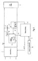
- Fig. 1 illustrated in a simplified manner and generally provided with the reference numeral 1 emergency lighting device according to the invention is provided in the illustrated embodiment for operating an LED as an emergency light source.
- the emergency light device 1 is connected on the input side to a power supply network, which provides a mains supply voltage U in , and has as essential components a control unit 2, a charging circuit 3, an energy storage unit 4 in the form of a battery or a rechargeable battery and a driver circuit 5.
- the charging circuit 3 is formed in the illustrated first embodiment by a so-called.
- Flyback converter having on the one hand a transformer T with a primary winding n1 and a secondary winding n2 and on the other hand, a controllable switch S1.
- a transformer T with a primary winding n1 and a secondary winding n2
- a controllable switch S1 In a known manner can be transmitted to the secondary side of the flyback converter 3 and charged for charging the energy storage unit 4 by a corresponding alternately opening and closing the switch S1 of the power supply voltage U in the available energy be used.
- the energy transfer takes place in the open state of the switch S1, wherein for this purpose on the output side of the flyback converter 3 further comprises a diode D 1 is provided.
- Such flyback circuits are often used due to their simple structure and their reliable function in such emergency lighting devices.
- the control of the controllable switch S1 is carried out by the control unit 2 of the emergency lighting device, wherein the control is effected in particular galvanically isolated via an optocoupler 6.
- t on1 corresponds to the switch-on time of the switch, while T designates the total duration of a complete switch cycle for the switch S1.
- the driver circuit 5 designed as a switching regulator has a further controllable switch S2, an inductance L and a diode D 2 .
- the switch S2 By alternately driving the switch S2 by the control unit 2, a current is provided in this way the LED over which it is operated.
- the duty cycle with which the switch S2 is controlled by the control unit 2 can be varied to adjust the height of the current supplied to the LED and thus the power at which the LED is operated. In this way it can be ensured in a very elegant way that even with fluctuating battery power the LED is operated despite everything with constant brightness.
- a function of the emergency light device 1 is thus to recognize by assessing the mains supply voltage U in , whether an emergency state is present, to possibly cause an emergency light operation. So far, it has been known to directly determine the value of the input voltage U in for the charging circuit 3, which, however, is associated with disadvantages for the reasons mentioned above.
- This relationship between the easily measured secondary voltage U flb2 and the input voltage U in to be monitored is now stored in the form of a value table in the control unit 2, so that it can determine the level of the input voltage U in in a simple manner after measurement of the secondary voltage U flb2 . without having to measure them directly.
- the control unit 2 determines that the input voltage U in is determined outside certain set value ranges, so this points to an emergency state back, which in turn will cause the control unit 2 to initiate an emergency service.
- Fig. 1 illustrated embodiment in that the height of the input voltage U in irrespective of whether the emergency light LED is turned on or not.
- the diode D 1 causes namely by their blocking effect a separation between secondary voltage U flb2 and battery voltage U Bat , so that the action of the driver circuit 3 does not affect the above-described process of determining the input voltage U in .
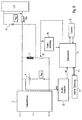
- FIG Fig. 2 A second, somewhat more general embodiment of an emergency lighting device according to the invention is shown in FIG Fig. 2 shown. This corresponds in its construction substantially to the in Fig. 1 shown emergency light device 1, however, now the charging circuit 3 is not formed by a flyback converter but generally by a circuit arrangement which has a potential separation and in turn controlled by the control unit 2 switch S1.
- both variables can be determined relatively simply, that is to say without galvanic isolation, since they in turn, like the control unit 2, which evaluates these measured variables, are at the same reference potential.
- the input voltage U in can then be determined since this is related to the three known quantities.
- These Characteristics are determined, for example, in the manufacture of the emergency lighting device and in turn deposited in the form of a table in the control unit 2. It can be seen that these characteristics are also dependent in particular on the input voltage U in . So now are the duty cycle D1 and the secondary power P flb2 of the charging circuit 3 is known, as well as in the example of Fig. 1 be closed to the height of the input voltage U in back.
- Driver circuit 5 is possible. In the example of Fig. 1 on the other hand, as already mentioned, this restriction does not exist. In principle, however, the control unit 2 will cause an activation of the driver circuit 5 and, accordingly, a switching on of the LED in the event of detection of a fault.
- the switch S2 can then be driven high-frequency in the manner described above in order to operate the LED with a desired power. In this case, to ensure that the power of the LED is constant, it would be necessary to know both the LED voltage U led and the LED current I led to enable regulation.
- an element 12 is connected, that may have the function of a linear regulator and / or a switch.
- this element 12 may be a transistor.
- a measuring resistor (shunt) 16 is further connected, so that the voltage drop across the shunt 16 is representative of the battery current.
- the measuring signal tapped off at the shunt 16 is fed to a current detection unit 13, which is preferably constructed as a discrete circuit and may have a comparator 14.
- the comparator 14 is just one example of how an offset to the measurement signal from the shunt 16 can be applied.
- the application of the offset serves, in a simplified way, the battery current be able to evaluate reproducing signals with different polarities in which the offset is selected so that the signal levels are shifted so that both signal polarities now have the same polarity and therefore different amplitudes.
- both the battery charging current and the battery discharge current which are known to have different polarities, can be measured in a relatively simple manner, for example by the control circuit 2.
- the control circuit 2 is thus preferably supplied with a measurement signal 15 having a uniform polarity.
- the transistor 12 is designed as a linear regulator, by means of the current detection unit 13 and activation of the linear regulator 12, a regulation of the battery discharge current and / or battery charging current can be carried out to a predetermined desired value.
- this scheme can of course also be designed as a protection circuit, so that at an excessively high battery charging current or battery discharge current, the switch 12 is opened to protect the battery 4.
- the battery 4 With very long failure of the mains voltage, a deep discharge of the battery 4 may occur.
- the battery 4 When the battery 4 is deeply discharged, it has a voltage of, for example, 1.3 volts, which is below the allowable voltage of, for example, 1.5 volts. Even if now a proper mains voltage applied to the input side of the charging circuit 3, and the charging circuit 3 is operated properly in the manner described above, the deep-discharged battery 4 will pull the secondary side of the charging circuit to the one unacceptably low value.
- this total discharge can be detected by detecting the voltage of the battery 4.
- the switch 12 is preferably operated clocked.
- the switch 12 is preferably closed only for a relatively short period of time, wherein a charging of the battery 4 takes place in this short period. Thereafter, however, the switch 12 is opened again to a longer period of time, so that the battery 4 is separated from the secondary side of the charging circuit 3 and the charging circuit 3 secondary side again can provide the proper voltage, for example, 1.5 volts.
- the switch 12 is opened again to a longer period of time, so that the battery 4 is separated from the secondary side of the charging circuit 3 and the charging circuit 3 secondary side again can provide the proper voltage, for example, 1.5 volts.
- the switch 12 While the switch 12 is open, the one mains voltage applied again by means of the charging circuit correctly supplies the connected LED driver circuit and LEDs. When the switch is closed for a short time, the battery is gently recharged.
- the duty cycle for the switch 12 may be selected to be closed only during 10% of the total time period and correspondingly 90% open so that the battery can recover in that 90% time period.
- Upon detected total discharge of the battery by means of the detection of the battery voltage can be switched automatically in this pulsed operation of the switch 12.
- the monitoring of the battery voltage via a discrete circuit and thus independent of the microcontroller 2 yes, if possible is not fully functional if the battery voltage is too low.
- the current detection circuit 13 with the comparator 14 is preferably selected as a discrete circuit and thus independently of the microcontroller 2 and its proper operation.
- FIG. 6 shows further details of an inventive LED driver circuit 5. All features of the battery circuit of FIG. 5 can be left with the circuit of FIG. 6 combine.
- the basic principle of the driver circuit 5 is, as already described, a switching regulator in which the coil L is magnetized when the switch S2 is closed and the magnetic energy discharges when the switch S2 is reopened via a current path which in series is a Zener diode, at least one LED and has an ohmic resistor 17.
- the resistor 17 is connected in series with the LEDs, this resistor 17 is an example of a current detection means.
- a current detection unit 18 may have, for example, a comparator 19.
- a current detection signal i. a signal representing the current through the LEDs is supplied to the control circuit 2.
- the control circuit 2 the switching behavior of the switch S2 u.a. configured depending on the current detection signal.
- a capacitor 30 is connected in parallel with the at least one LED.
- the capacitor 30 smoothes the LED current by storing energy and keeping the voltage across the at least one LED substantially constant.
- the capacitor 30 is dimensioned such that further the regulation of the LED voltage is possible.
- FIG. 7 schematically shows the driving of the switch S2, that is, in the case that this switch is designed as a FET transistor, the driving of the gate of this transistor in the sync with the self-adjusting current through the LEDs.
- the current through the LEDs increases in each case.
- the off period it decreases again, driven by the magnetic energy of the coil L. This results in a zigzag shape of the current through the LED around a fixed DC value.
- the current detection should now be able to determine in particular the time average of this current, so as to be able to select, for example, the power of the LEDs either to a constant value or to a freely selectable value (dimming).
- control circuit 2 which prescribes the switching behavior of the switch S2 and thus knows, determines the current value to a first measuring point A and to a second measuring point B in order to obtain it again to form the mean. From the mean value of the current value at the time of measurement A and the time of measurement B, the time average of the LED current then results.
- the measuring point A is chosen so that it is in the range of the end of the switching off of the switch S2, while the time B is selected such that it is at the end of the switch-on.
- a measurement of a plurality of minimum and maximum values is carried out for one measurement cycle.
- inaccuracies in the measurement time can be found out.
- the measurement times are synchronized with the timing of the switch S2.
- this synchronization can lead to inaccuracies, which are justified, for example, by the delays of A / D converters. These inaccuracies are averaged out by capturing multiple values.
- the control unit 2 can adjust depending on the switching frequency and / or the duty cycle of the switch S2.
- the control unit 2 may, for example, superimpose the high-frequency clocking of the switch S2 with a modulation which is low-frequency in comparison thereto, for example in the form of a PWM modulation. This represents an alternative or additional possibility for dimming, since, as stated above, the dimming can also take place by changing the high-frequency clocking of the switch S2 itself.
- the dimming of the LED ie the setting of the LED current to a defined selectable value
- the dimming can also be effected as a function of other variables. For example, the dimming depending on a detected battery discharge current (see circuit of FIG. 5 ), thus extending the battery life.
- the driver circuit 5 can also dim the LED when the average value of the mains voltage supplying the charging circuit 3 drops below a predetermined value.
- a further assistive measure for extending the battery life of the flyback converter can be placed in the charging circuit 3 in a pulsed operation, so that so the flyback converter assisted to the weakening battery voltage, the driver circuit 5 supplies.
- the battery voltage can be detected (see again FIG. 5 ).
- an LED voltage detection can take place.
- a soft-start function can be provided, in which the control circuit 2 first lets a relatively small test current flow through the LED (s) during startup.
- the test measurement is to determine electrical parameters to find out whether one or which LED is connected to the driver circuit 5. For example, it can be determined which LED voltage results in the given test current. From this conclusions can be drawn on the type (color) and number of connected LEDs be taken, in turn, depending on the steady-state operating current adapted to the determined LED type to regulate.
- control unit 2 during startup increases the LED current by corresponding activation of the switch S2 of the driver circuit 5, starting from a low value to the stationary operating value for the LED current.
- a repetition of the application of the test voltage may occur automatically at predetermined intervals until the onset of a proper LED is detected.
- a repetition of the application of the test voltage may occur automatically at predetermined intervals until the onset of a proper LED is detected.
- the current through the LED can be done either by superimposing a low-frequency modulation on the high-frequency clocking of the switch S2 and / or by a change (duty cycle, frequency) of the high-frequency clocking itself.
- control unit 2 can be designed as a digital integrated circuit, particularly a software-controlled circuit, such as a microcontroller. If the microcontroller 2 does not function properly, it may happen that the microcontroller 2 permanently switches the switch S2 of the LED driver circuit 5 to the closed (conducting) state.
- this discrete fault detection circuit 20 may include a capacitor that integrates the gate drive signal of the switch S2, thus detecting the state of permanently turning on the LED drive switch S2. With permanent concern of the turn-on signal (logic high) so the voltage to the capacitor of the fault detection circuit 20 increases, which could be discharged at a logic 'low' signal, for example, via a resistor.
- the fault detection circuit 20 is connected to the microcontroller 2, i. If the turn-on signal at the LED driver circuit S2 is permanently applied, a signal builds up on the capacitor of the fault detection circuit 20, which signal is conducted to a pin of the microcontroller 2 provided for this purpose. When this signal is present at the pin of the microcontroller 2, it is provided that the current operating data of the microcontroller 2 are stored in a memory 21. Thereafter, the microcontroller 2 performs a restart after a reset.
- a comparable process can be triggered when a detection circuit for the battery voltage 4 determines that the supply voltage of the microcontroller 2, for example, drops well below the target value of 1.5 volts. Also in this case, the operation data from the microcontroller 2 in the Memory 21 stored. Of course, a restart of the microcontroller 2 only takes place again when a sufficient supply voltage for the microcontroller 2 has been detected.
- the supply voltage Vs for the microcontroller 2 by means of a switching power supply (DC / DC converter) 22 is provided.
- the DC / DC converter 22 may be designed in the form of a so-called boost converter (buck / boost converter) such that at low battery voltage (for example in the case of a deep discharge) the boosting ratio is increased and thus a sufficient supply voltage for the microcontroller 2 is still available is provided.
- boost converter buck / boost converter
- the microcontroller 2 causes the microcontroller 2, if after a prolonged failure of the power supply voltage then the battery voltage drops, switching off all circuit parts that are not purely necessary for the supply of the microcontroller 2.
- the microcontroller 2 is in a standby state. In this standby state, furthermore, the interface of the microcontroller 2 is functional, which in particular monitors incoming bus signals from the bus line 11 and thus from an external control unit 10.
- the microcontroller 2 can also process an incoming digital signal (eg DALI signal) or comparable signals in this standby state.
- the operational amplifier 14 of the current control 13 of the battery 4 can be deactivated at very low battery.
Landscapes
- Business, Economics & Management (AREA)
- Emergency Management (AREA)
- Engineering & Computer Science (AREA)
- Power Engineering (AREA)
- Circuit Arrangement For Electric Light Sources In General (AREA)
- Charge And Discharge Circuits For Batteries Or The Like (AREA)
- Circuit Arrangements For Discharge Lamps (AREA)
Applications Claiming Priority (3)
| Application Number | Priority Date | Filing Date | Title |
|---|---|---|---|
| DE102006018531 | 2006-04-21 | ||
| DE102006030655A DE102006030655A1 (de) | 2006-04-21 | 2006-07-03 | Notlichtgerät zum Betreiben einer Lichtquelle, insbesondere einer LED |
| EP20070702902 EP2011212B1 (fr) | 2006-04-21 | 2007-01-19 | Alimentation en tension pour unité de commande d'appareil d'éclairage de secours |
Related Parent Applications (2)
| Application Number | Title | Priority Date | Filing Date |
|---|---|---|---|
| EP07702902.3 Division | 2007-01-19 | ||
| EP20070702902 Division EP2011212B1 (fr) | 2006-04-21 | 2007-01-19 | Alimentation en tension pour unité de commande d'appareil d'éclairage de secours |
Publications (2)
| Publication Number | Publication Date |
|---|---|
| EP2249459A1 true EP2249459A1 (fr) | 2010-11-10 |
| EP2249459B1 EP2249459B1 (fr) | 2014-06-18 |
Family
ID=37762525
Family Applications (11)
| Application Number | Title | Priority Date | Filing Date |
|---|---|---|---|
| EP20110154704 Active EP2323240B1 (fr) | 2006-04-21 | 2007-01-19 | Circuit de commande de DEL |
| EP10168831.5A Active EP2249459B1 (fr) | 2006-04-21 | 2007-01-19 | Tension d'alimentation pour une unité de commande d'un circuit d'éclairage de secours |
| EP20070702903 Active EP2011214B1 (fr) | 2006-04-21 | 2007-01-19 | Circuit de batterie dans un appareil d'éclairage de secours |
| EP20070702902 Active EP2011212B1 (fr) | 2006-04-21 | 2007-01-19 | Alimentation en tension pour unité de commande d'appareil d'éclairage de secours |
| EP10169401.6A Active EP2234240B1 (fr) | 2006-04-21 | 2007-01-19 | Circuit de commande de DEL |
| EP07702901A Active EP2011211B1 (fr) | 2006-04-21 | 2007-01-19 | Circuit de charge pour une lumière de secours |
| EP13198488.2A Active EP2717425B1 (fr) | 2006-04-21 | 2007-01-19 | Circuit de commande de DEL |
| EP10168045.2A Not-in-force EP2242163B1 (fr) | 2006-04-21 | 2007-01-19 | Circuit de batteries dans un appareil d'éclairage de secours |
| EP07702900A Active EP2011213B1 (fr) | 2006-04-21 | 2007-01-19 | Circuit d'excitation de diode électroluminescente |
| EP10168858A Not-in-force EP2249458B1 (fr) | 2006-04-21 | 2007-04-11 | Appareil d'éclairage de secours pour commander une source lumineuse, en particulier une DEL |
| EP07724164A Active EP2013959B1 (fr) | 2006-04-21 | 2007-04-11 | Appareil de lumière de secours pour le fonctionnement d'une source lumineuse, en particulier une del |
Family Applications Before (1)
| Application Number | Title | Priority Date | Filing Date |
|---|---|---|---|
| EP20110154704 Active EP2323240B1 (fr) | 2006-04-21 | 2007-01-19 | Circuit de commande de DEL |
Family Applications After (9)
| Application Number | Title | Priority Date | Filing Date |
|---|---|---|---|
| EP20070702903 Active EP2011214B1 (fr) | 2006-04-21 | 2007-01-19 | Circuit de batterie dans un appareil d'éclairage de secours |
| EP20070702902 Active EP2011212B1 (fr) | 2006-04-21 | 2007-01-19 | Alimentation en tension pour unité de commande d'appareil d'éclairage de secours |
| EP10169401.6A Active EP2234240B1 (fr) | 2006-04-21 | 2007-01-19 | Circuit de commande de DEL |
| EP07702901A Active EP2011211B1 (fr) | 2006-04-21 | 2007-01-19 | Circuit de charge pour une lumière de secours |
| EP13198488.2A Active EP2717425B1 (fr) | 2006-04-21 | 2007-01-19 | Circuit de commande de DEL |
| EP10168045.2A Not-in-force EP2242163B1 (fr) | 2006-04-21 | 2007-01-19 | Circuit de batteries dans un appareil d'éclairage de secours |
| EP07702900A Active EP2011213B1 (fr) | 2006-04-21 | 2007-01-19 | Circuit d'excitation de diode électroluminescente |
| EP10168858A Not-in-force EP2249458B1 (fr) | 2006-04-21 | 2007-04-11 | Appareil d'éclairage de secours pour commander une source lumineuse, en particulier une DEL |
| EP07724164A Active EP2013959B1 (fr) | 2006-04-21 | 2007-04-11 | Appareil de lumière de secours pour le fonctionnement d'une source lumineuse, en particulier une del |
Country Status (6)
| Country | Link |
|---|---|
| US (3) | US8680778B2 (fr) |
| EP (11) | EP2323240B1 (fr) |
| AT (5) | ATE473537T1 (fr) |
| DE (4) | DE102006030655A1 (fr) |
| ES (2) | ES2347829T3 (fr) |
| WO (5) | WO2007121801A1 (fr) |
Cited By (2)
| Publication number | Priority date | Publication date | Assignee | Title |
|---|---|---|---|---|
| US10461573B2 (en) | 2015-02-25 | 2019-10-29 | Tridonic Gmbh & Co Kg | Emergency power supply unit and method for operating an emergency lighting means |
| DE112011101246B4 (de) | 2010-04-09 | 2023-03-09 | Tridonic Ag | Modulares LED-Beleuchtungssystem mit Notlichtfunktion |
Families Citing this family (46)
| Publication number | Priority date | Publication date | Assignee | Title |
|---|---|---|---|---|
| DE102006030655A1 (de) * | 2006-04-21 | 2007-10-25 | Tridonicatco Gmbh & Co. Kg | Notlichtgerät zum Betreiben einer Lichtquelle, insbesondere einer LED |
| ITVI20070029A1 (it) * | 2007-01-31 | 2008-08-01 | Beghelli Spa | Sistema elettronico di controllo della ricarica per batterie di accumulatori, in particolare per lampade di illuminazione di emergenza |
| DE202008008977U1 (de) * | 2008-07-04 | 2009-11-19 | Pasedag, Roland | Beleuchtungskörper, insbesondere in der Form einer Rettungszeichenleuchte |
| TWI580305B (zh) | 2008-09-05 | 2017-04-21 | 艾杜雷控股有限公司 | 以發光二極體為光源之照明系統 |
| US8957601B2 (en) | 2008-09-18 | 2015-02-17 | Lumastream Canada Ulc | Configurable LED driver/dimmer for solid state lighting applications |
| DE102008055862A1 (de) * | 2008-11-05 | 2010-05-06 | Tridonicatco Gmbh & Co. Kg | Leuchtmittel-Betriebsgerät mit Potentialtrennung |
| DE102009019229A1 (de) * | 2009-04-28 | 2010-11-04 | Tridonicatco Gmbh & Co. Kg | Leistungsgeregelte Betriebsschaltung für ein Leuchtmittel sowie Verfahren zum Betreiben derselben |
| DE112010001814A5 (de) * | 2009-04-30 | 2012-05-31 | Tridonic Gmbh & Co Kg | Notlichtbetriebsgerät mit potentialgetrennten pfc-einheit |
| CA2766422C (fr) * | 2009-06-05 | 2016-12-13 | Polynom Ag | Circuit electronique permettant de convertir un eclairage sur secteur en un eclairage de secours |
| DE102009044593B4 (de) * | 2009-11-19 | 2018-07-12 | Vossloh-Schwabe Deutschland Gmbh | Betriebssteuergerät zum Betreiben eines Leuchtmittels |
| ES2364308B2 (es) * | 2010-02-19 | 2012-03-13 | Universidad De Oviedo | Sistema de dimming pwm en serie a alta frefuencia para aplicación en convertidores de din�?mica lenta para l�?mparas de estado sólido. |
| CN101771294B (zh) | 2010-03-05 | 2012-08-15 | 矽力杰半导体技术(杭州)有限公司 | 集合驱动控制电路及其控制方法 |
| IT1398695B1 (it) * | 2010-03-09 | 2013-03-08 | Tci Telecomunicazioni Italia Srl | Rivelatore presenza rete ac per lampade a led provviste di modalita' emergenza |
| DE102010003797A1 (de) * | 2010-04-09 | 2011-10-13 | Tridonic Ag | Modulares LED-Beleuchtungssystem mit Notlichtfunktion |
| CN101861025B (zh) * | 2010-06-10 | 2014-07-09 | 鸿富锦精密工业(深圳)有限公司 | Led发光装置及其驱动电路 |
| WO2012049566A1 (fr) | 2010-10-14 | 2012-04-19 | Japan Tobacco Inc. | Polythérapie pour l'utilisation dans le traitement du diabète |
| AU2012277331B2 (en) * | 2011-06-30 | 2017-01-19 | Schneider Electric Industries Sas | Dual power SMPS for a modular lighting system |
| US9510405B2 (en) * | 2011-06-30 | 2016-11-29 | Schneider Electric Industries Sas | Dual power SMPS for a modular lighting system |
| DE102011080996B4 (de) | 2011-08-16 | 2024-02-15 | Tridonic Gmbh & Co Kg | Betrieb eines Leuchtmittels mit autonomem Energiespeicher |
| DE102011086067A1 (de) * | 2011-11-10 | 2013-05-16 | Tridonic Gmbh & Co. Kg | Notlichtgerät mit konstanter Leistung |
| EP2608357B1 (fr) * | 2011-12-19 | 2014-07-23 | Vetco Gray Controls Limited | Protection contre les transitoires dans un système de communication |
| DE102012100348B4 (de) | 2012-01-17 | 2018-08-16 | P.E.R. Flucht- Und Rettungsleitsysteme Gmbh | Dynamisches flucht- und rettungsleitsystem |
| GB201204106D0 (en) * | 2012-03-08 | 2012-04-18 | Tridonic Uk Ltd | Lamp unit power supply system |
| DE102012214832B4 (de) | 2012-08-21 | 2024-11-28 | Tridonic Uk Ltd. | Notlichtgerät mit Potentialtrennung zwischen Leuchtmittel und Energiespeicher |
| CN103023320B (zh) | 2012-11-23 | 2014-09-03 | 矽力杰半导体技术(杭州)有限公司 | 一种高效率的双向直流变换器及其控制方法 |
| US8970134B2 (en) * | 2013-03-11 | 2015-03-03 | Osram Sylvania Inc. | Systems and methods of preventing strobing light output |
| EP2781824B1 (fr) | 2013-03-18 | 2018-05-09 | Helvar Oy Ab | Pilote de source de lumière |
| DE102013219153B4 (de) * | 2013-09-24 | 2024-05-16 | Tridonic Gmbh & Co Kg | Treibermodul mit sekundärseitiger Erkennung einer primärseitigen elektrischen Versorgung |
| AT14758U1 (de) * | 2013-09-25 | 2016-05-15 | Tridonic Gmbh & Co Kg | Treibermodul mit sekundärseitiger Erkennung einer primärseitigen elektrischen Versorgung |
| DE202013104447U1 (de) * | 2013-09-30 | 2015-01-08 | Halemeier Gmbh & Co. Kg | Schaltung zur Energieversorgung einer Leuchte an einem beweglichen Möbelteil |
| DE102014102843B4 (de) | 2014-03-04 | 2023-09-28 | Optotronic Gmbh | Eingangsspannung erkennendes Betriebsgerät für Leuchtmittel |
| US9999108B2 (en) | 2014-05-14 | 2018-06-12 | Philips Lighting Holding B.V. | Emergency lighting driver with programmable output power |
| RU2713382C2 (ru) * | 2015-04-07 | 2020-02-05 | Филипс Лайтинг Холдинг Б.В. | Нагрузка, питаемая от источника электроснабжения или перезаряжаемого источника |
| WO2016168073A1 (fr) | 2015-04-16 | 2016-10-20 | Hubbell Incorporated | Appareil de gradation d'urgence |
| WO2016201346A1 (fr) | 2015-06-12 | 2016-12-15 | Villaume Edward | Dispositifs, systèmes et procédés d'éclairage d'urgence |
| ITUB20155559A1 (it) | 2015-11-13 | 2017-05-13 | Beghelli Spa | Alimentatore di emergenza per apparecchi di illuminazione |
| NL2015923B1 (en) * | 2015-12-08 | 2017-06-28 | Eldolab Holding Bv | LED driver. |
| GB2558674B (en) * | 2017-01-10 | 2022-01-19 | Tridonic Gmbh & Co Kg | Apparatus for operating one or more lighting devices |
| GB2562739B (en) * | 2017-05-22 | 2022-01-26 | Tridonic Gmbh & Co Kg | Fast closed loop system using microcontroller |
| US11026311B2 (en) | 2017-06-19 | 2021-06-01 | Abl Ip Holding Llc | Emergency lighting system with power rollback |
| DE202017104950U1 (de) * | 2017-08-17 | 2018-11-20 | Tridonic Gmbh & Co Kg | Energieeffiziente Notlicht-LED-Treibervorrichtung und Beleuchtungseinrichtung |
| US10344929B1 (en) | 2017-09-01 | 2019-07-09 | Heathco, Llc | Battery backup for lighting system |
| DE102017220553A1 (de) * | 2017-11-17 | 2019-05-23 | Tridonic Gmbh & Co Kg | Notlicht-Betriebsgerät, Notlicht-Modul und Verfahren zur Steuerung eines Notlicht-Betriebsgeräts |
| CN112088481B (zh) * | 2018-05-15 | 2024-06-14 | 三菱电机株式会社 | 功率器件驱动装置及其制造方法 |
| JP6870656B2 (ja) * | 2018-05-17 | 2021-05-12 | 三菱電機株式会社 | 非常用点灯装置 |
| USD909165S1 (en) | 2019-08-27 | 2021-02-02 | Kennametal Inc | Adapter block |
Citations (2)
| Publication number | Priority date | Publication date | Assignee | Title |
|---|---|---|---|---|
| EP1202428A1 (fr) * | 2000-10-31 | 2002-05-02 | MAGNETEK S.p.A. | Bloc d'éclairage de sécurité, un dispositif comprenant ce bloc, et procédé de commande de ceux-ci |
| US6502044B1 (en) * | 1999-07-12 | 2002-12-31 | Acuity Brands Inc. | Self-diagnostic circuitry for emergency lighting fixtures |
Family Cites Families (45)
| Publication number | Priority date | Publication date | Assignee | Title |
|---|---|---|---|---|
| US4323820A (en) * | 1980-03-27 | 1982-04-06 | Foxmar Industries Inc. | Emergency lighting system |
| DE3639116A1 (de) * | 1986-11-15 | 1988-05-19 | Trilux Lenze Gmbh & Co Kg | Gleichspannungsversorgungsschaltung fuer leuchtstofflampen |
| US5444378A (en) * | 1988-07-13 | 1995-08-22 | Electronic Development Inc. | Battery state of charge monitor |
| US4890004A (en) * | 1988-11-21 | 1989-12-26 | Beckerman Howard L | Emergency light control and battery charging system |
| US5172009A (en) | 1991-02-25 | 1992-12-15 | Regents Of The University Of Minnesota | Standby power supply with load-current harmonics neutralizer |
| GB9109996D0 (en) * | 1991-05-03 | 1991-07-03 | Protec Fire Detection Plc | Lighting |
| US5214352A (en) * | 1991-06-07 | 1993-05-25 | Computer Power Inc. | Light dimming system for emergency operation |
| EP0539640A1 (fr) * | 1991-10-30 | 1993-05-05 | Texas Instruments Limited | Perfectionnements des batteries |
| JPH05319184A (ja) * | 1992-05-18 | 1993-12-03 | Mitsubishi Electric Corp | 車両用電源電圧切換装置 |
| US5400009A (en) * | 1993-10-07 | 1995-03-21 | Wheelock Inc. | Synchronization circuit for visual/audio alarms |
| GB2303979B (en) * | 1995-08-02 | 2000-03-29 | Mitsubishi Electric Corp | A control system and control method for uninterruptible power supply |
| US5646502A (en) * | 1995-08-28 | 1997-07-08 | Nsi Enterprises, Inc. | Emergency lighting circuit for shunt-regulated battery charging and lamp operation |
| US5656925A (en) * | 1996-01-22 | 1997-08-12 | Juno Lighting, Inc. | Pulse switching tandem flyback voltage converter |
| SE519550C2 (sv) * | 1997-01-03 | 2003-03-11 | Ericsson Telefon Ab L M | Drivkrets samt förfarande för att driva en sådan drivkrets |
| FI104034B (fi) | 1998-03-30 | 1999-10-29 | Teknoware Oy | Menetelmä ja laite tehon syöttämiseksi valodiodeille |
| FI106770B (fi) * | 1999-01-22 | 2001-03-30 | Nokia Mobile Phones Ltd | Valaiseva elektroninen laite ja valaisumenetelmä |
| JP4230589B2 (ja) * | 1999-02-16 | 2009-02-25 | 日置電機株式会社 | 測定システム |
| JP3503542B2 (ja) * | 1999-09-20 | 2004-03-08 | ウシオ電機株式会社 | 外部電極式希ガス蛍光ランプの点灯装置 |
| DE10025821A1 (de) * | 2000-05-25 | 2002-07-25 | Sickinger Monika | Led-Lichtquelle |
| US6642692B2 (en) * | 2000-06-23 | 2003-11-04 | Honda Giken Kogyo Kabushiki Kaisha | Charge equalizing device for power storage unit |
| US6304039B1 (en) * | 2000-08-08 | 2001-10-16 | E-Lite Technologies, Inc. | Power supply for illuminating an electro-luminescent panel |
| FI111323B (fi) | 2001-07-04 | 2003-06-30 | Teknoware Oy | Turvavalojärjestely ja turvavalolaite |
| GB2382238B (en) * | 2001-08-25 | 2005-04-06 | Mackwell Electronics Ltd | Emergency lighting |
| US7015654B1 (en) * | 2001-11-16 | 2006-03-21 | Laughing Rabbit, Inc. | Light emitting diode driver circuit and method |
| JP2003164072A (ja) * | 2001-11-28 | 2003-06-06 | Hitachi Ltd | 停電補償電源装置 |
| US6624599B1 (en) * | 2002-03-13 | 2003-09-23 | Fego Precision Industrial Co., Ltd. | Compact single-stage electronic ballast circuit for emergency lighting applications |
| US6798152B2 (en) * | 2002-08-21 | 2004-09-28 | Freescale Semiconductor, Inc. | Closed loop current control circuit and method thereof |
| CN100370685C (zh) * | 2002-08-30 | 2008-02-20 | 三垦电气株式会社 | 开关电源装置 |
| ATE436173T1 (de) * | 2002-10-16 | 2009-07-15 | Ccs Inc | Stromversorgungssystem für eine lumineszenzdiodeneinheit |
| US20050001562A1 (en) * | 2003-07-02 | 2005-01-06 | 911Ep, Inc. | LED compensation circuit |
| DE10337148A1 (de) * | 2003-08-13 | 2005-03-17 | Sander Elektronik Ag | Notbeleuchtung |
| JP4052998B2 (ja) * | 2003-11-25 | 2008-02-27 | シャープ株式会社 | 電源回路及びそれを用いた電子機器 |
| US6933678B2 (en) * | 2003-12-10 | 2005-08-23 | Chao-Tung Kuo | Emergency lighting function illumination appliance |
| US7129652B2 (en) * | 2004-03-26 | 2006-10-31 | Texas Instruments Incorporated | System and method for driving a plurality of loads |
| US20050264217A1 (en) * | 2004-06-01 | 2005-12-01 | Huston Trevor L | Controller for power protection |
| US7202608B2 (en) * | 2004-06-30 | 2007-04-10 | Tir Systems Ltd. | Switched constant current driving and control circuit |
| US7256556B2 (en) | 2004-09-28 | 2007-08-14 | Acuity Brands, Inc. | Equipment and methods for emergency lighting that provides brownout detection and protection |
| JP4400880B2 (ja) * | 2004-10-05 | 2010-01-20 | 株式会社小糸製作所 | 車両用灯具の点灯制御回路 |
| JP4306657B2 (ja) * | 2004-10-14 | 2009-08-05 | ソニー株式会社 | 発光素子駆動装置および表示装置 |
| WO2006092040A1 (fr) * | 2005-03-03 | 2006-09-08 | Tir Systems Ltd. | Procede et appareil de commande de contrainte thermique dans des dispositifs electroluminescents |
| US7049758B2 (en) * | 2005-04-01 | 2006-05-23 | Osram Sylvania Inc. | Method of soft-starting a switching power supply having time-based pulse triggering control |
| CN2861732Y (zh) * | 2005-09-26 | 2007-01-24 | 黄重荣 | 多功能灯具 |
| US8491159B2 (en) * | 2006-03-28 | 2013-07-23 | Wireless Environment, Llc | Wireless emergency lighting system |
| DE102006030655A1 (de) * | 2006-04-21 | 2007-10-25 | Tridonicatco Gmbh & Co. Kg | Notlichtgerät zum Betreiben einer Lichtquelle, insbesondere einer LED |
| US7671538B2 (en) * | 2007-07-26 | 2010-03-02 | Odo Innovations Ltd. | Method and system for economical emergency activation of electrical devices |
-
2006
- 2006-07-03 DE DE102006030655A patent/DE102006030655A1/de not_active Withdrawn
-
2007
- 2007-01-19 AT AT07702903T patent/ATE473537T1/de active
- 2007-01-19 DE DE200750004135 patent/DE502007004135D1/de active Active
- 2007-01-19 AT AT07702900T patent/ATE553524T1/de active
- 2007-01-19 EP EP20110154704 patent/EP2323240B1/fr active Active
- 2007-01-19 EP EP10168831.5A patent/EP2249459B1/fr active Active
- 2007-01-19 WO PCT/EP2007/000474 patent/WO2007121801A1/fr not_active Ceased
- 2007-01-19 US US12/296,504 patent/US8680778B2/en not_active Expired - Fee Related
- 2007-01-19 ES ES07702901T patent/ES2347829T3/es active Active
- 2007-01-19 DE DE200750004327 patent/DE502007004327D1/de active Active
- 2007-01-19 ES ES07702903T patent/ES2348912T3/es active Active
- 2007-01-19 AT AT07702902T patent/ATE494653T1/de active
- 2007-01-19 EP EP20070702903 patent/EP2011214B1/fr active Active
- 2007-01-19 EP EP20070702902 patent/EP2011212B1/fr active Active
- 2007-01-19 EP EP10169401.6A patent/EP2234240B1/fr active Active
- 2007-01-19 DE DE200750006190 patent/DE502007006190D1/de active Active
- 2007-01-19 EP EP07702901A patent/EP2011211B1/fr active Active
- 2007-01-19 EP EP13198488.2A patent/EP2717425B1/fr active Active
- 2007-01-19 WO PCT/EP2007/000473 patent/WO2007121800A1/fr not_active Ceased
- 2007-01-19 AT AT07702901T patent/ATE471588T1/de active
- 2007-01-19 EP EP10168045.2A patent/EP2242163B1/fr not_active Not-in-force
- 2007-01-19 WO PCT/EP2007/000471 patent/WO2007121798A1/fr not_active Ceased
- 2007-01-19 EP EP07702900A patent/EP2011213B1/fr active Active
- 2007-01-19 WO PCT/EP2007/000472 patent/WO2007121799A1/fr not_active Ceased
- 2007-04-11 AT AT07724164T patent/ATE535981T1/de active
- 2007-04-11 EP EP10168858A patent/EP2249458B1/fr not_active Not-in-force
- 2007-04-11 WO PCT/EP2007/003223 patent/WO2007121860A1/fr not_active Ceased
- 2007-04-11 EP EP07724164A patent/EP2013959B1/fr active Active
- 2007-04-11 US US12/297,900 patent/US8716936B2/en active Active
-
2011
- 2011-11-30 US US13/307,268 patent/US8796946B2/en active Active
Patent Citations (2)
| Publication number | Priority date | Publication date | Assignee | Title |
|---|---|---|---|---|
| US6502044B1 (en) * | 1999-07-12 | 2002-12-31 | Acuity Brands Inc. | Self-diagnostic circuitry for emergency lighting fixtures |
| EP1202428A1 (fr) * | 2000-10-31 | 2002-05-02 | MAGNETEK S.p.A. | Bloc d'éclairage de sécurité, un dispositif comprenant ce bloc, et procédé de commande de ceux-ci |
Non-Patent Citations (1)
| Title |
|---|
| MARCOS ALONSO J ET AL: "A Microcontroller-Based Emergency Ballast for Fluorescent Lamps", IEEE TRANSACTIONS ON INDUSTRIAL ELECTRONICS, IEEE SERVICE CENTER, PISCATAWAY, NJ, USA, vol. 44, no. 2, 1 April 1997 (1997-04-01), XP011023247, ISSN: 0278-0046 * |
Cited By (2)
| Publication number | Priority date | Publication date | Assignee | Title |
|---|---|---|---|---|
| DE112011101246B4 (de) | 2010-04-09 | 2023-03-09 | Tridonic Ag | Modulares LED-Beleuchtungssystem mit Notlichtfunktion |
| US10461573B2 (en) | 2015-02-25 | 2019-10-29 | Tridonic Gmbh & Co Kg | Emergency power supply unit and method for operating an emergency lighting means |
Also Published As
Similar Documents
| Publication | Publication Date | Title |
|---|---|---|
| EP2011212B1 (fr) | Alimentation en tension pour unité de commande d'appareil d'éclairage de secours | |
| EP2888800B1 (fr) | Appareil de lumière de secours | |
| DE112014002232B4 (de) | Betriebsschaltung für LED | |
| EP2523533A2 (fr) | Circuit de ballast pour diodes luminescentes | |
| WO2012045477A1 (fr) | Détection de défaillance pour des diodes électroluminescentes | |
| EP2992738B1 (fr) | Reconnaissance d'erreur pour del | |
| DE102013211767A1 (de) | Betriebsschaltung für leuchtdioden | |
| EP2796012B1 (fr) | Procédé, appareillage d'alimentation et système d'éclairage, avec détection d'effet de redressement de lampes | |
| DE102018007411A1 (de) | Led-dimmen | |
| EP1819207A1 (fr) | Procédé et dispositif destinés à l'allumage d'une lampe fluorescente | |
| DE102012206044A1 (de) | Betrieb von Leuchtdioden | |
| EP3439159A1 (fr) | Réduction de fluctuations de flux lumineux dans une commande de valeur seuil d'un convertisseur cadencé activement | |
| DE212014000115U1 (de) | Betriebsschaltung für Leuchtdioden mit Filterelement |
Legal Events
| Date | Code | Title | Description |
|---|---|---|---|
| PUAI | Public reference made under article 153(3) epc to a published international application that has entered the european phase |
Free format text: ORIGINAL CODE: 0009012 |
|
| AC | Divisional application: reference to earlier application |
Ref document number: 2011212 Country of ref document: EP Kind code of ref document: P |
|
| AK | Designated contracting states |
Kind code of ref document: A1 Designated state(s): AT BE BG CH CY CZ DE DK EE ES FI FR GB GR HU IE IS IT LI LT LU LV MC NL PL PT RO SE SI SK TR |
|
| 17P | Request for examination filed |
Effective date: 20110505 |
|
| RIC1 | Information provided on ipc code assigned before grant |
Ipc: H02J 9/06 20060101AFI20110620BHEP |
|
| 17Q | First examination report despatched |
Effective date: 20110915 |
|
| GRAP | Despatch of communication of intention to grant a patent |
Free format text: ORIGINAL CODE: EPIDOSNIGR1 |
|
| RIC1 | Information provided on ipc code assigned before grant |
Ipc: H05B 33/08 20060101ALI20120213BHEP Ipc: H02J 9/06 20060101AFI20120213BHEP Ipc: H02J 9/02 20060101ALI20120213BHEP |
|
| GRAS | Grant fee paid |
Free format text: ORIGINAL CODE: EPIDOSNIGR3 |
|
| GRAJ | Information related to disapproval of communication of intention to grant by the applicant or resumption of examination proceedings by the epo deleted |
Free format text: ORIGINAL CODE: EPIDOSDIGR1 |
|
| GRAL | Information related to payment of fee for publishing/printing deleted |
Free format text: ORIGINAL CODE: EPIDOSDIGR3 |
|
| INTC | Intention to grant announced (deleted) | ||
| GRAP | Despatch of communication of intention to grant a patent |
Free format text: ORIGINAL CODE: EPIDOSNIGR1 |
|
| INTG | Intention to grant announced |
Effective date: 20140110 |
|
| GRAS | Grant fee paid |
Free format text: ORIGINAL CODE: EPIDOSNIGR3 |
|
| GRAA | (expected) grant |
Free format text: ORIGINAL CODE: 0009210 |
|
| AC | Divisional application: reference to earlier application |
Ref document number: 2011212 Country of ref document: EP Kind code of ref document: P |
|
| AK | Designated contracting states |
Kind code of ref document: B1 Designated state(s): AT BE BG CH CY CZ DE DK EE ES FI FR GB GR HU IE IS IT LI LT LU LV MC NL PL PT RO SE SI SK TR |
|
| REG | Reference to a national code |
Ref country code: GB Ref legal event code: FG4D Free format text: NOT ENGLISH |
|
| REG | Reference to a national code |
Ref country code: CH Ref legal event code: EP |
|
| REG | Reference to a national code |
Ref country code: AT Ref legal event code: REF Ref document number: 673845 Country of ref document: AT Kind code of ref document: T Effective date: 20140715 |
|
| REG | Reference to a national code |
Ref country code: IE Ref legal event code: FG4D Free format text: LANGUAGE OF EP DOCUMENT: GERMAN |
|
| REG | Reference to a national code |
Ref country code: DE Ref legal event code: R096 Ref document number: 502007013216 Country of ref document: DE Effective date: 20140807 |
|
| PG25 | Lapsed in a contracting state [announced via postgrant information from national office to epo] |
Ref country code: CY Free format text: LAPSE BECAUSE OF FAILURE TO SUBMIT A TRANSLATION OF THE DESCRIPTION OR TO PAY THE FEE WITHIN THE PRESCRIBED TIME-LIMIT Effective date: 20140618 Ref country code: LT Free format text: LAPSE BECAUSE OF FAILURE TO SUBMIT A TRANSLATION OF THE DESCRIPTION OR TO PAY THE FEE WITHIN THE PRESCRIBED TIME-LIMIT Effective date: 20140618 Ref country code: FI Free format text: LAPSE BECAUSE OF FAILURE TO SUBMIT A TRANSLATION OF THE DESCRIPTION OR TO PAY THE FEE WITHIN THE PRESCRIBED TIME-LIMIT Effective date: 20140618 Ref country code: GR Free format text: LAPSE BECAUSE OF FAILURE TO SUBMIT A TRANSLATION OF THE DESCRIPTION OR TO PAY THE FEE WITHIN THE PRESCRIBED TIME-LIMIT Effective date: 20140919 |
|
| REG | Reference to a national code |
Ref country code: NL Ref legal event code: VDEP Effective date: 20140618 |
|
| REG | Reference to a national code |
Ref country code: LT Ref legal event code: MG4D |
|
| PG25 | Lapsed in a contracting state [announced via postgrant information from national office to epo] |
Ref country code: LV Free format text: LAPSE BECAUSE OF FAILURE TO SUBMIT A TRANSLATION OF THE DESCRIPTION OR TO PAY THE FEE WITHIN THE PRESCRIBED TIME-LIMIT Effective date: 20140618 Ref country code: SE Free format text: LAPSE BECAUSE OF FAILURE TO SUBMIT A TRANSLATION OF THE DESCRIPTION OR TO PAY THE FEE WITHIN THE PRESCRIBED TIME-LIMIT Effective date: 20140618 |
|
| PG25 | Lapsed in a contracting state [announced via postgrant information from national office to epo] |
Ref country code: RO Free format text: LAPSE BECAUSE OF FAILURE TO SUBMIT A TRANSLATION OF THE DESCRIPTION OR TO PAY THE FEE WITHIN THE PRESCRIBED TIME-LIMIT Effective date: 20140618 Ref country code: EE Free format text: LAPSE BECAUSE OF FAILURE TO SUBMIT A TRANSLATION OF THE DESCRIPTION OR TO PAY THE FEE WITHIN THE PRESCRIBED TIME-LIMIT Effective date: 20140618 Ref country code: ES Free format text: LAPSE BECAUSE OF FAILURE TO SUBMIT A TRANSLATION OF THE DESCRIPTION OR TO PAY THE FEE WITHIN THE PRESCRIBED TIME-LIMIT Effective date: 20140618 Ref country code: CZ Free format text: LAPSE BECAUSE OF FAILURE TO SUBMIT A TRANSLATION OF THE DESCRIPTION OR TO PAY THE FEE WITHIN THE PRESCRIBED TIME-LIMIT Effective date: 20140618 Ref country code: PT Free format text: LAPSE BECAUSE OF FAILURE TO SUBMIT A TRANSLATION OF THE DESCRIPTION OR TO PAY THE FEE WITHIN THE PRESCRIBED TIME-LIMIT Effective date: 20141020 Ref country code: SK Free format text: LAPSE BECAUSE OF FAILURE TO SUBMIT A TRANSLATION OF THE DESCRIPTION OR TO PAY THE FEE WITHIN THE PRESCRIBED TIME-LIMIT Effective date: 20140618 |
|
| PG25 | Lapsed in a contracting state [announced via postgrant information from national office to epo] |
Ref country code: NL Free format text: LAPSE BECAUSE OF FAILURE TO SUBMIT A TRANSLATION OF THE DESCRIPTION OR TO PAY THE FEE WITHIN THE PRESCRIBED TIME-LIMIT Effective date: 20140618 Ref country code: IS Free format text: LAPSE BECAUSE OF FAILURE TO SUBMIT A TRANSLATION OF THE DESCRIPTION OR TO PAY THE FEE WITHIN THE PRESCRIBED TIME-LIMIT Effective date: 20141018 Ref country code: PL Free format text: LAPSE BECAUSE OF FAILURE TO SUBMIT A TRANSLATION OF THE DESCRIPTION OR TO PAY THE FEE WITHIN THE PRESCRIBED TIME-LIMIT Effective date: 20140618 |
|
| REG | Reference to a national code |
Ref country code: DE Ref legal event code: R097 Ref document number: 502007013216 Country of ref document: DE |
|
| PLBE | No opposition filed within time limit |
Free format text: ORIGINAL CODE: 0009261 |
|
| STAA | Information on the status of an ep patent application or granted ep patent |
Free format text: STATUS: NO OPPOSITION FILED WITHIN TIME LIMIT |
|
| PG25 | Lapsed in a contracting state [announced via postgrant information from national office to epo] |
Ref country code: IT Free format text: LAPSE BECAUSE OF FAILURE TO SUBMIT A TRANSLATION OF THE DESCRIPTION OR TO PAY THE FEE WITHIN THE PRESCRIBED TIME-LIMIT Effective date: 20140618 Ref country code: DK Free format text: LAPSE BECAUSE OF FAILURE TO SUBMIT A TRANSLATION OF THE DESCRIPTION OR TO PAY THE FEE WITHIN THE PRESCRIBED TIME-LIMIT Effective date: 20140618 |
|
| 26N | No opposition filed |
Effective date: 20150319 |
|
| PG25 | Lapsed in a contracting state [announced via postgrant information from national office to epo] |
Ref country code: BE Free format text: LAPSE BECAUSE OF NON-PAYMENT OF DUE FEES Effective date: 20150131 |
|
| PG25 | Lapsed in a contracting state [announced via postgrant information from national office to epo] |
Ref country code: SI Free format text: LAPSE BECAUSE OF FAILURE TO SUBMIT A TRANSLATION OF THE DESCRIPTION OR TO PAY THE FEE WITHIN THE PRESCRIBED TIME-LIMIT Effective date: 20140618 |
|
| REG | Reference to a national code |
Ref country code: CH Ref legal event code: PL |
|
| PG25 | Lapsed in a contracting state [announced via postgrant information from national office to epo] |
Ref country code: LU Free format text: LAPSE BECAUSE OF FAILURE TO SUBMIT A TRANSLATION OF THE DESCRIPTION OR TO PAY THE FEE WITHIN THE PRESCRIBED TIME-LIMIT Effective date: 20150119 |
|
| PG25 | Lapsed in a contracting state [announced via postgrant information from national office to epo] |
Ref country code: MC Free format text: LAPSE BECAUSE OF FAILURE TO SUBMIT A TRANSLATION OF THE DESCRIPTION OR TO PAY THE FEE WITHIN THE PRESCRIBED TIME-LIMIT Effective date: 20140618 |
|
| PG25 | Lapsed in a contracting state [announced via postgrant information from national office to epo] |
Ref country code: CH Free format text: LAPSE BECAUSE OF NON-PAYMENT OF DUE FEES Effective date: 20150131 Ref country code: LI Free format text: LAPSE BECAUSE OF NON-PAYMENT OF DUE FEES Effective date: 20150131 |
|
| REG | Reference to a national code |
Ref country code: IE Ref legal event code: MM4A |
|
| PG25 | Lapsed in a contracting state [announced via postgrant information from national office to epo] |
Ref country code: IE Free format text: LAPSE BECAUSE OF NON-PAYMENT OF DUE FEES Effective date: 20150119 |
|
| REG | Reference to a national code |
Ref country code: FR Ref legal event code: PLFP Year of fee payment: 10 |
|
| PGFP | Annual fee paid to national office [announced via postgrant information from national office to epo] |
Ref country code: AT Payment date: 20160128 Year of fee payment: 10 |
|
| REG | Reference to a national code |
Ref country code: FR Ref legal event code: PLFP Year of fee payment: 11 |
|
| PG25 | Lapsed in a contracting state [announced via postgrant information from national office to epo] |
Ref country code: HU Free format text: LAPSE BECAUSE OF FAILURE TO SUBMIT A TRANSLATION OF THE DESCRIPTION OR TO PAY THE FEE WITHIN THE PRESCRIBED TIME-LIMIT; INVALID AB INITIO Effective date: 20070119 Ref country code: BG Free format text: LAPSE BECAUSE OF FAILURE TO SUBMIT A TRANSLATION OF THE DESCRIPTION OR TO PAY THE FEE WITHIN THE PRESCRIBED TIME-LIMIT Effective date: 20140618 |
|
| PG25 | Lapsed in a contracting state [announced via postgrant information from national office to epo] |
Ref country code: TR Free format text: LAPSE BECAUSE OF FAILURE TO SUBMIT A TRANSLATION OF THE DESCRIPTION OR TO PAY THE FEE WITHIN THE PRESCRIBED TIME-LIMIT Effective date: 20140618 |
|
| REG | Reference to a national code |
Ref country code: AT Ref legal event code: MM01 Ref document number: 673845 Country of ref document: AT Kind code of ref document: T Effective date: 20170119 |
|
| PG25 | Lapsed in a contracting state [announced via postgrant information from national office to epo] |
Ref country code: AT Free format text: LAPSE BECAUSE OF NON-PAYMENT OF DUE FEES Effective date: 20170119 |
|
| REG | Reference to a national code |
Ref country code: FR Ref legal event code: PLFP Year of fee payment: 12 |
|
| REG | Reference to a national code |
Ref country code: DE Ref legal event code: R084 Ref document number: 502007013216 Country of ref document: DE |
|
| PGFP | Annual fee paid to national office [announced via postgrant information from national office to epo] |
Ref country code: FR Payment date: 20200128 Year of fee payment: 14 |
|
| PG25 | Lapsed in a contracting state [announced via postgrant information from national office to epo] |
Ref country code: FR Free format text: LAPSE BECAUSE OF NON-PAYMENT OF DUE FEES Effective date: 20210131 |
|
| P01 | Opt-out of the competence of the unified patent court (upc) registered |
Effective date: 20230530 |
|
| PGFP | Annual fee paid to national office [announced via postgrant information from national office to epo] |
Ref country code: DE Payment date: 20240129 Year of fee payment: 18 |
|
| PGFP | Annual fee paid to national office [announced via postgrant information from national office to epo] |
Ref country code: GB Payment date: 20250121 Year of fee payment: 19 |
|
| REG | Reference to a national code |
Ref country code: DE Ref legal event code: R119 Ref document number: 502007013216 Country of ref document: DE |
|
| PG25 | Lapsed in a contracting state [announced via postgrant information from national office to epo] |
Ref country code: DE Free format text: LAPSE BECAUSE OF NON-PAYMENT OF DUE FEES Effective date: 20250801 |