EP2249675B1 - Bagage à roulettes perfectionné - Google Patents
Bagage à roulettes perfectionné Download PDFInfo
- Publication number
- EP2249675B1 EP2249675B1 EP09836135A EP09836135A EP2249675B1 EP 2249675 B1 EP2249675 B1 EP 2249675B1 EP 09836135 A EP09836135 A EP 09836135A EP 09836135 A EP09836135 A EP 09836135A EP 2249675 B1 EP2249675 B1 EP 2249675B1
- Authority
- EP
- European Patent Office
- Prior art keywords
- box
- platform
- piece
- luggage
- luggage according
- Prior art date
- Legal status (The legal status is an assumption and is not a legal conclusion. Google has not performed a legal analysis and makes no representation as to the accuracy of the status listed.)
- Active
Links
Images



Classifications
-
- A—HUMAN NECESSITIES
- A45—HAND OR TRAVELLING ARTICLES
- A45C—PURSES; LUGGAGE; HAND CARRIED BAGS
- A45C5/00—Rigid or semi-rigid luggage
- A45C5/14—Rigid or semi-rigid luggage with built-in rolling means
-
- A—HUMAN NECESSITIES
- A45—HAND OR TRAVELLING ARTICLES
- A45C—PURSES; LUGGAGE; HAND CARRIED BAGS
- A45C5/00—Rigid or semi-rigid luggage
- A45C5/14—Rigid or semi-rigid luggage with built-in rolling means
- A45C5/146—Rigid or semi-rigid luggage with built-in rolling means retractable
-
- B—PERFORMING OPERATIONS; TRANSPORTING
- B62—LAND VEHICLES FOR TRAVELLING OTHERWISE THAN ON RAILS
- B62K—CYCLES; CYCLE FRAMES; CYCLE STEERING DEVICES; RIDER-OPERATED TERMINAL CONTROLS SPECIALLY ADAPTED FOR CYCLES; CYCLE AXLE SUSPENSIONS; CYCLE SIDECARS, FORECARS, OR THE LIKE
- B62K15/00—Collapsible or foldable cycles
- B62K15/006—Collapsible or foldable cycles the frame being foldable
-
- B—PERFORMING OPERATIONS; TRANSPORTING
- B62—LAND VEHICLES FOR TRAVELLING OTHERWISE THAN ON RAILS
- B62K—CYCLES; CYCLE FRAMES; CYCLE STEERING DEVICES; RIDER-OPERATED TERMINAL CONTROLS SPECIALLY ADAPTED FOR CYCLES; CYCLE AXLE SUSPENSIONS; CYCLE SIDECARS, FORECARS, OR THE LIKE
- B62K3/00—Bicycles
- B62K3/002—Bicycles without a seat, i.e. the rider operating the vehicle in a standing position, e.g. non-motorized scooters; non-motorized scooters with skis or runners
-
- A—HUMAN NECESSITIES
- A45—HAND OR TRAVELLING ARTICLES
- A45C—PURSES; LUGGAGE; HAND CARRIED BAGS
- A45C9/00—Purses, Luggage or bags convertible into objects for other use
- A45C2009/005—Purses, Luggage or bags convertible into objects for other use into a vehicle, e.g. scooter
Definitions
- the invention relates to the field of luggage and more particularly luggage on wheels.
- Baggage of this type is already known, which comprises a box with a bottom provided with two spaced wheels and a top extended by a handle, generally telescopic, for moving the box in a substantially vertical position.
- the luggage can thus be used in two different modes: a conventional carrying mode in which the luggage is lifted from the ground and carried by the handle in the retracted position and a driving mode in which the luggage is rolled on the ground and pulled by the handle in the out position.
- a conventional carrying mode in which the luggage is lifted from the ground and carried by the handle in the retracted position
- a driving mode in which the luggage is rolled on the ground and pulled by the handle in the out position.
- the rollers In the first mode the rollers are inoperative, while in the second mode the rollers roll on the ground and relieve the efforts of the user.
- this luggage is a hit with the public and is produced in a wide variety of shapes and sizes.
- the invention proposes for this purpose a bag of the type defined in introduction, which comprises a movable plate whose one end is connected by a hinge mechanism to the bottom of the box and another end is provided with a support wheel, the movable plate being movable between a storage position, in which the tray is retracted along a large face of the box, and a service position in which the plate forms a chosen angle with said large face of the box, so that the support wheel can rest on the ground and form with the two wheels of the luggage a three-wheeled support to transport a user standing on the board and standing at the handle.
- the luggage of the invention is provided with a movable plate that can be placed either in a storage position along the box, or in a service position to form then a kind of step supported by the two wheels of the box and the support wheel of the tray in the manner of a tricycle.
- the luggage In the storage position, the luggage is used in the usual carrying mode, the movable plate being inoperative.
- the movable platen In the service position, the movable platen is operational. The user is then standing on the board and stands at the same time at the handle. He can then press one foot on the ground intermittently to move the luggage in the manner of a scooter.
- the two casters of the casing being arranged forward with respect to the platen support roller.
- a bag containing the features of the preamble of claim 1 is known to FR-A-2818100 .
- the luggage of the invention comprises, in addition to the movable plate, an engine embedded in the box adapted to be actuated at the request of the user to allow it to be transported effortlessly with the box.
- the box houses an electric motor connected to a battery pack to rotate at least one of the wheels at the request of the user.
- the additional weight and space generated by the motor and the tray can be minimized so as not to cause excessive overload and not penalize the useful volume of the box.
- the baggage 10 comprises a box 12, in the example of generally parallelepipedal shape, disposed in a substantially vertical position.
- the box 12 comprises a bottom 14 constituted here by a face of generally rectangular shape and by a top 16 also constituted by a face of generally rectangular shape.
- the bottom 14 of the box 12 is provided with two spaced wheels 18 and 20, at least one of which (here the wheel 18) can be rotated by motorization means (described below) housed in a technical compartment 22 located in the bottom region and surmounted by a useful compartment 24 for housing the items to be transported in the box 12.
- motorization means housed in a technical compartment 22 located in the bottom region and surmounted by a useful compartment 24 for housing the items to be transported in the box 12.
- the bottom 14 of the box 12 has two long sides, a large front side 26 and a large rear side 28 and two small sides 30 and 32.
- the two casters 18 and 20 are located respectively close to two small sides 30, 32 being arranged at the ends of an axle extending parallel to the long sides and more particularly near the large rear side 28.
- the bottom 14 of the box are arranged wheel arches 34 and 36 respectively accommodating the wheels 18 and 20 ( figure 2 ).
- the bottom 14 further comprises at least one retractable stand 37 movable between an extended position ( figure 3 ) and a retracted position ( figures 1 and 4 ).
- two crutches 37 are located near the long front side 26. The operation of these crutches will be described in detail below.
- the box is further limited mainly by a front face 38, a rear face 40 also called "large face", and two other side faces (not referenced).
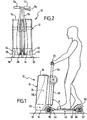
- the luggage 10 of the invention further comprises a movable plate 42, a front end 44 is formed in the form of a fork ( figure 6 ) forming a hinge mechanism 46 with a flange 48 mounted in the lower part of the rear face 40 of the box near the bottom 14.
- the movable plate 40 has a rear end 50 which is provided with a support wheel 52.
- the casing 12 is extended at its apex by a double handle 54 mounted at one end of a telescopic handle 56 housed in the casing along the large face 40 (rear face) of the latter.
- the handle can move from a retracted position near the top of the box (not shown) to a telescoped position, away from the top of the box, as shown on the Figures 1 and 2 . The user can then hold on to the handle with both hands, as seen on the figure 1 .
- the support wheel 52 is surmounted by a wheel protector 58 pivotally mounted about an axis 60 and also acting as a brake. As we see on the figure 1 , the user can, with the foot, press on the wheel guard 58 to brake the support wheel 52.
- the movable plate 42 can also take a storage position in which it is retracted along the large face 40 of the box, as also sketched on the Figures 1 and 2 . Moving the storage position to the service position, and vice versa, is done by a pivoting approximately 90 °. In the service position represented in Figures 1 and 2 , the plate forms a selected angle A, here of substantially 90 °, with the large face 40 of the box.
- the support wheel 52 can rest on the ground and form with the two casters 18 and 20 of the casing a three-wheel support for transporting the user as shown in FIG. figure 1 .
- This three-wheeled carrier is similar to a sort of tricycle, whose wheels 18 and 20 form the front wheels and the support wheel 52 forms the rear wheel, the box 12 being disposed in front of the user in the direction normal progress.
- the articulation mechanism 46 here comprises a double articulation, to allow on the one hand the aforementioned pivoting along the angle A around an axis XX ( figures 4 and 6 ), and secondly a limited angular travel D around a YY axis as shown in FIG. figure 5 .
- This angular deflection which can be for example 10 °, allows the luggage to steer.
- the front end 44 of the movable plate pivots relative to the flange 48 about the axis XX, which is substantially horizontal in the position of use of the luggage.
- the flange 48 can itself pivot about the axis YY, perpendicular to the axis XX, which is substantially vertical in the position of use of the luggage.
- the flange 48 is pivotally mounted at the lower end of a column 61 ( figure 6 ) extending along the large face 40 of the box.
- the flange 48 could be connected to the column 61 by a deformable element allowing a Rotational or torsional movement over a limited angular interval.
- the baggage When the tray is in the retracted position ( figure 3 ) the baggage may be shot on the ground in the usual manner by a user as shown in figure 3 . In this case, the user pulls the baggage 10 which is then placed behind him, like a standard luggage with wheels, the handle 54 being in the extended position, therefore remote from the top 16 of the box.
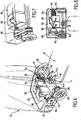
- FIGs 4 and 5 show three positions of the movable plate 42, namely a storage position P1 as described above, in which the movable plate is retracted along the large face 40 of the housing, a service position P2 as described above where the wheel of support 52 comes to rest on the ground and an intermediate position P3 called "open position damped".
- the luggage of the invention further comprises a damping cylinder 62 ( Figures 4 and 5 ) of which a front end 64 is articulated to the box 12 at a distance from the hinge 46 and a rear end 66 of which is articulated to the mobile plate 42.
- This damper cylinder 62 allows a dampened descent movement of the movable plate 42 from the storage position P1 to the damped open position P3, with an angular displacement of about 60 °.
- the displacement of the damped open position P3 to the service position P2 corresponds to an angular displacement of approximately 30 ° and is effected by means of an assist pedal 68 ( figure 5 ).
- a locking mechanism 70 which will be described in detail later ( figure 9 ), keeps the moving platen in the service position.
- This locking mechanism 70 can be controlled by the foot or by an actuating pedal carried by the plate, for example by the pedal 68 already mentioned.
- the large face 40 (rear face) of the box comprises a recess 72 forming a storage area for the movable plate 42 in the storage position.
- This recess 72 is extended in the upper part by a recess 74 adapted to house the support wheel 52.
- the box 12 is provided in the upper part with a movable flap 76 capable of concealing the support wheel 52 when the plate is in position. the storage position.
- this flap is of curved shape and is connected by a hinge pin 78 to the large face 40 of the box. This component thus makes it possible to conceal the support wheel and to prevent any contact thereof with the user, for example with his clothes.
- the flap 76 is first raised manually as shown by the arrow F 1 on the figure 4 . This lift frees the support roller 52, which makes it possible to move the movable plate from the storage position P 1 to the damped opening position P 3 with the assistance of the cylinder 62, as shown by the arrow F 2 . Then the user must press the pedal 68 ( figure 5 ) to move the movable plate from the damped open position P 3 to the service position P 2 . The transition from position P 3 to position P 2 also causes the return of the crutches 37 that were previously out, as discussed below.
- These means comprise an electric motor 80 powered by a rechargeable battery 82 (here a double battery), itself connected to an electric charger 84.
- the electric motor 80, the battery 82 and other equipment such as the charger 84 are housed in the technical compartment 22.
- the electric motor 80 is connected to at least one of the casters of the casing, here the caster 18, by a drive mechanism to ensure its driving in rotation.
- This mechanism comprises a pulley 86 keyed on the axis of the motor, a pulley 88 connected to the wheel 18 by means of a freewheel mechanism (not shown) and a belt 90 winding around the pulleys 86 and 88 .
- the charger 84 is provided with an electrical cord 92 for connection to the mains.
- this power cord is mounted on a winder mechanism and it ends with an electrical outlet 94 for connection to the mains.
- the tray When the tray is in the service position, it is sufficient for the user to operate the electric motor by means of a handle 96 ( figure 2 ) on the handle 54.
- the luggage When the engine is stopped, the luggage can move thanks to the freewheel mechanism. The user can at any time brake the luggage by pressing the wheel protector 58 acting as a brake.
- the motor assembly housed in the technical compartment can be made sufficiently compact so as not to affect the useful volume of the box.
- the movable plate and its support wheel can easily retract into the recesses 72 and 74 and not penalize the useful volume of the box.
- the weight and bulk caused by the motorization and the movable plate are not likely to cause overweight or penalize the useful volume of the box.
- the electric motor has a power of less than 250W to meet the regulations.
- the maximum speed is limited to 6Km / h to avoid wearing the helmet.
- the empty weight of the luggage is about 13 kg and the carrying capacity is about 35 liters.
- a NiMH type battery is advantageously used because of its superior performance to that of lead batteries. Such a battery allows 1000 recharging cycles and its charging time is at most 4 hours.
- the locking mechanism 70 may for example be in the form of a compass mechanism as shown in FIG. figure 9 .
- This mechanism comprises a rod 98 articulated about an axis 100 to the box 12 and hinged about an axis 102 to a second link 104, which is articulated about an axis 106 to the movable plate 42.
- the links 98 and 104 shown in solid lines
- the links are substantially aligned, the axis 102 being slightly retracted relative to the alignment of the axes 100 and 106 to allow locking.
- the links shown in broken lines
- the legs 37 are each pivotally mounted about an axis 108 and are connected about a hinge pin 110 at one end of a connecting rod 112 incorporating a spring 114.
- the other end of the rod link 112 is articulated on an extension 116 of the front end 44 of the movable plate 42.
- the retractable legs 37 are movable between an extended position when the tray is in the storage position and a retracted position when the tray is in the service position. When the tray is moved from the storage position to the service position, the stands initially in the extended position begin to pivot to the retracted position approximately from the half open position.
- the shape and dimensions of the box may vary depending on the desired uses.
- the box can be provided with other equipment, for example additional casters, a fixed additional handle, etc.
- the invention thus provides a luggage whose movement, especially over large distances, is favored. It applies generally to luggage, such as suitcases, saddlebags, trunks, etc.
Landscapes
- Engineering & Computer Science (AREA)
- Mechanical Engineering (AREA)
- Purses, Travelling Bags, Baskets, Or Suitcases (AREA)
- Handcart (AREA)
Description
- L'invention se rapporte au domaine des bagages et plus particulièrement des bagages à roulettes.
- On connaît déjà des bagages de ce type, qui comprennent un caisson avec un fond muni de deux roulettes espacées et un sommet prolongé par une poignée, généralement télescopique, pour le déplacement du caisson dans une position sensiblement verticale.
- Le bagage peut ainsi être utilisé selon deux modes différents : un mode de portage classique dans lequel le bagage est soulevé du sol et porté par la poignée en position rentrée et un mode de roulage dans lequel le bagage est roulé sur le sol et tiré par la poignée en position sortie. Dans le premier mode les roulettes sont inopérantes, tandis que dans le second mode les roulettes roulent sur le sol et soulagent les efforts de l'utilisateur.
- Compte tenu de leur polyvalence ces bagages rencontrent un grand succès auprès du public et sont produits dans une grande variété de formes et de dimensions.
- Toutefois, en mode de roulage, le déplacement d'un tel bagage peut être pénible pour certaines personnes, surtout lorsque ce déplacement s'effectue sur une grande distance et que le poids du bagage est élevé.
- C'est en conséquence l'un des buts de l'invention de proposer un bagage du type précité qui soit équipé de moyens pour faciliter son déplacement dans le mode de roulage au sol.
- L'invention propose à cet effet un bagage du type défini en introduction, lequel comprend un plateau mobile dont une extrémité est reliée par un mécanisme d'articulation au fond du caisson et dont une autre extrémité est munie d'une roulette d'appui, le plateau mobile étant déplaçable entre une position de rangement, en laquelle le plateau est escamoté le long d'une grande face du caisson, et une position de service en laquelle le plateau forme un angle choisi avec ladite grande face du caisson, en sorte que la roulette d'appui peut reposer au sol et former avec les deux roulettes du bagage un support à trois roues pour transporter un utilisateur en position debout sur le plateau et se tenant à la poignée.
- Ainsi, le bagage de l'invention est muni d'un plateau mobile pouvant être placé soit dans une position de rangement le long du caisson, soit dans une position de service pour former alors une sorte de marchepied supporté par les deux roulettes du caisson et la roulette d'appui du plateau à la manière d'un tricycle.
- Dans la position de rangement, le bagage est utilisé dans le mode de portage habituel, le plateau mobile étant inopérant.
- Dans la position de service, le plateau mobile est opérationnel. L'utilisateur est alors debout sur le plateau et se tient en même temps à la poignée. Il peut alors appuyer un pied au sol par intermittence pour faire avancer le bagage à la manière d'une patinette.
- Ainsi dans la position de service l'utilisateur se trouve placé derrière le caisson par rapport au sens de déplacement, les deux roulettes du caisson étant disposées en avant par rapport à la roulette d'appui du plateau.
- Le passage de la position de rangement à la position de service, ou inversement, peut se faire très rapidement en offrant ainsi une grande souplesse de fonctionnement à l'utilisateur.
Un bagage comportant les caractéristiques du préambule de la revendication 1 est connu parFR-A-2818100
Le bagage de l'invention comporte, en plus du plateau mobile, une motorisation embarquée dans le caisson apte à être actionnée à la demande de l'utilisateur pour lui permettre d'être transporté sans effort avec le caisson. - Le caisson loge un moteur électrique relié à une batterie d'alimentation pour entraîner en rotation l'une au moins des roulettes à la demande de l'utilisateur.
- Le poids et l'encombrement supplémentaires engendrés par la motorisation et le plateau peuvent être minimisés pour ne pas entraîner une surcharge excessive et ne pas pénaliser le volume utile du caisson.
- Dans la description qui suit, faite seulement à titre d'exemple, on se réfère aux dessins annexés, sur lesquels :
- la
figure 1 est une vue de côté d'un bagage selon l'invention représenté en position de service, un utilisateur se tenant debout sur le plateau mobile ; - la
figure 2 est une vue par l'arrière du bagage de lafigure 1 , sans l'utilisateur ; - la
figure 3 est une vue de côté du bagage avec le plateau mobile en position de rangement, le bagage étant tiré par un utilisateur ; - la
figure 4 est une vue de côté du bagage, le plateau mobile étant représenté dans trois positions : une position de rangement, une position de service et une position intermédiaire dite d'ouverture amortie ; - la
figure 5 est une vue en perspective analogue à lafigure 4 montrant le plateau mobile dans les mêmes trois positions ; - la
figure 6 est une vue partielle en perspective du bagage montrant des moyens de motorisation associés à l'une des roulettes du caisson : - la
figure 7 est une autre vue partielle en perspective des moyens de motorisation et de la roulette associée ; - la
figure 8 est une vue de dessus correspondant à lafigure 6 ; et - la
figure 9 est une vue partielle de côté, analogue à lafigure 4 , montrant un mécanisme de verrouillage du plateau et des béquilles escamotables. - On se réfère d'abord à la
figure 1 qui montre de côté un bagage selon l'invention désigné dans son ensemble par la référence 10. Le bagage 10 comprend un caisson 12, dans l'exemple de forme générale parallélépipédique, disposé dans une position sensiblement verticale. Le caisson 12 comprend un fond 14 constitué ici par une face de forme générale rectangulaire et par un sommet 16 constitué également par une face de forme générale rectangulaire. - Le fond 14 du caisson 12 est muni de deux roulettes espacées 18 et 20 dont l'une au moins (ici la roulette 18) peut être entraînée en rotation par des moyens de motorisation (décrits plus loin) logés dans un compartiment technique 22 situé dans la région du fond et surmonté par un compartiment utile 24 destiné à loger les articles à transporter dans le caisson 12.
- Le fond 14 du caisson 12 comporte deux grands côtés, un grand côté avant 26 et un grand côté arrière 28 et deux petits côtés 30 et 32. Les deux roulettes 18 et 20 sont situées respectivement à proximité de deux petits côtés 30, 32 en étant disposées aux extrémités d'un essieu s'étendant parallèlement aux grands côtés et plus particulièrement à proximité du grand côté arrière 28.
- Dans le fond 14 du caisson sont aménagés des passages de roue 34 et 36 accueillant respectivement les roulettes 18 et 20 (
figure 2 ). Le fond 14 comprend en outre au moins une béquille escamotable 37 déplaçable entre une position sortie (figure 3 ) et une position rentrée (figures 1 et4 ). Dans l'exemple deux béquilles 37 sont situées près du grand côté avant 26. Le fonctionnement de ces béquilles sera décrit en détail plus loin. - Le caisson est limité en outre principalement par une face avant 38, une face arrière 40 appelée aussi « grande face », et deux autres faces latérales (non référencées).
- Le bagage 10 de l'invention comprend en outre un plateau mobile 42 dont une extrémité avant 44 est réalisée sous la forme d'une fourche (
figure 6 ) formant un mécanisme d'articulation 46 avec une bride 48 montée en partie inférieure de la face arrière 40 du caisson près du fond 14. Le plateau mobile 40 comporte une extrémité arrière 50 qui est munie d'une roulette d'appui 52. - Le caisson 12 est prolongé à son sommet par une poignée double 54 montée à une extrémité d'un manche télescopique 56 logé dans le caisson le long de la grande face 40 (face arrière) de ce dernier. La poignée peut se déplacer d'une position escamotée proche du sommet du caisson (non représenté) à une position télescopée, éloignée du sommet du caisson, comme représenté sur les
figures 1 et 2 . L'utilisateur peut alors se tenir à la poignée avec ses deux mains, comme on le voit sur lafigure 1 . - La roulette d'appui 52 est surmontée par un protège-roue 58 monté pivotant autour d'un axe 60 et faisant également office de frein. Comme on le voit sur la
figure 1 , l'utilisateur peut, à l'aide du pied, appuyer sur le protège-roue 58 pour freiner la roulette d'appui 52. - Le plateau mobile 42 peut en outre prendre une position de rangement en laquelle il est escamoté le long de la grande face 40 du caisson, comme esquissé également sur les
figures 1 et 2 . Le déplacement de la position de rangement à la position de service, et inversement, se fait par un pivotement d'approximativement 90°. Dans la position de service représentée auxfigures 1 et 2 , le plateau forme un angle choisi A, ici de sensiblement 90°, avec la grande face 40 du caisson. - Dans la position de service, la roulette d'appui 52 peut reposer au sol et former avec les deux roulettes 18 et 20 du caisson un support à trois roues pour transporter l'utilisateur comme montré sur la
figure 1 . Ce support à trois roues s'apparente à une sorte de tricycle, dont les roulettes 18 et 20 forment les roues avant et la roulette d'appui 52 forme la roue arrière, le caisson 12 étant disposé en avant de l'utilisateur dans le sens normal d'avancement. - Le mécanisme d'articulation 46 comporte ici une double articulation, pour permettre d'une part le pivotement précité suivant l'angle A autour d'un axe X-X (
figures 4 et6 ), et d'autre part un débattement angulaire limité D autour d'un axe Y-Y comme montré à lafigure 5 . Ce débattement angulaire, qui peut être par exemple de 10°, permet au bagage de braquer. - L'extrémité avant 44 du plateau mobile pivote par rapport à la bride 48 autour de l'axe X-X, qui est sensiblement horizontal dans la position d'utilisation du bagage. La bride 48 peut elle-même pivoter autour de l'axe Y-Y, perpendiculaire à l'axe X-X, qui est sensiblement vertical dans la position d'utilisation du bagage. La bride 48 est ici montée pivotante à l'extrémité inférieure d'une colonne 61 (
figure 6 ) s'étendant le long de la grande face 40 du caisson. En variante la bride 48 pourrait être reliée à la colonne 61 par un élément déformable autorisant un mouvement de rotation ou de torsion sur un intervalle angulaire limité. - Lorsque le plateau est dans la position escamotée (
figure 3 ) le bagage peut être tiré au sol de la manière habituelle par un utilisateur comme montré à lafigure 3 . Dans ce cas, l'utilisateur tire le bagage 10 qui est alors disposé derrière lui, comme un bagage classique à roulettes, la poignée 54 étant en position sortie, donc éloignée du sommet 16 du caisson. - On se réfère maintenant aux
figures 4 et 5 qui montrent trois positions du plateau mobile 42, à savoir une position de rangement P1 comme décrite précédemment, dans laquelle le plateau mobile est escamoté le long de la grande face 40 du caisson, une position de service P2 comme décrite précédemment où la roulette d'appui 52 vient reposer au sol et une position intermédiaire P3 dite « position ouverte amortie ». - Le bagage de l'invention comprend en outre un vérin amortisseur 62 (
figures 4 et 5 ) dont une extrémité avant 64 est articulée au caisson 12 à distance de l'articulation 46 et dont une extrémité arrière 66 est articulée au plateau mobile 42. - Ce vérin amortisseur 62 permet un mouvement de descente amortie du plateau mobile 42 à partir de la position de rangement P1 jusqu'à la position ouverte amortie P3, avec un débattement angulaire d'environ 60°. Le déplacement de la position ouverte amortie P3 à la position de service P2 correspond à un déplacement angulaire d'environ 30° et s'effectue au moyen d'une pédale d'assistance 68 (
figure 5 ). Un mécanisme de verrouillage 70, qui sera décrit en détail plus loin (figure 9 ), permet de maintenir le plateau mobile dans la position de service. Ce mécanisme de verrouillage 70 peut être commandé au pied ou par une pédale d'actionnement portée par le plateau, par exemple par la pédale 68 déjà citée. - Comme on peut le voir plus particulièrement sur la
figure 5 , la grande face 40 (face arrière) du caisson comprend un évidement 72 formant une zone de stockage pour le plateau mobile 42 dans la position de rangement. Cet évidement 72 se prolonge en partie supérieure par un évidement 74 adapté pour loger la roulette d'appui 52. Le caisson 12 est muni en partie supérieure d'un volet mobile 76 propre à dissimuler la roulette d'appui 52 lorsque le plateau est dans la position de rangement. Dans l'exemple, ce volet est de forme incurvée et il est relié par un axe d'articulation 78 à la grande face 40 du caisson. Ce volet permet ainsi de dissimuler la roulette d'appui et d'empêcher tout contact de celle-ci avec l'utilisateur, par exemple avec ses vêtements. - Pour passer de la position de rangement à la position de service, le volet 76 est d'abord relevé manuellement comme montré par la flèche F1 sur la
figure 4 . Ce relevage libère la roulette d'appui 52, ce qui permet de faire passer le plateau mobile de la position de rangement P1 à la position d'ouverture amortie P3 avec l'assistance du vérin 62, comme montré par la flèche F2. Ensuite l'utilisateur doit appuyer sur la pédale 68 (figure 5 ) pour faire passer le plateau mobile de la position ouverte amortie P3 à la position de service P2. Le passage de la position P3 à la position P2 provoque aussi la rentrée des béquilles 37 qui étaient auparavant sorties, comme on le verra plus loin. - On se réfère maintenant plus particulièrement aux
figures 6 à 8 pour décrire les moyens de motorisation logés dans le compartiment technique 22 situé en partie inférieure du caisson 12. - Ces moyens comprennent un moteur électrique 80 alimenté par une batterie rechargeable 82 (ici une batterie double), elle-même reliée à un chargeur électrique 84. Le moteur électrique 80, la batterie 82 et d'autres équipements tels que le chargeur 84 sont logés dans le compartiment technique 22.
- Le moteur électrique 80 est relié à l'une au moins des roulettes du caisson, ici la roulette 18, par un mécanisme d'entraînement pour assurer son entraînement en rotation. Ce mécanisme comprend une poulie 86 calée sur l'axe du moteur, une poulie 88 reliée à la roulette 18 par l'intermédiaire d'un mécanisme à roue libre (non représenté) et une courroie 90 s'enroulant autour des poulies 86 et 88.
- Le chargeur 84 est muni d'un cordon électrique 92 pour le raccordement au secteur électrique. Dans l'exemple, ce cordon électrique est monté sur un mécanisme à enrouleur et il se termine par une prise électrique 94 pour le raccordement au secteur. Ainsi, pour recharger la ou les batteries, il convient de dérouler le cordon 92 et de brancher la prise électrique 94 sur le secteur. Une fois l'opération de chargement terminée, le cordon vient s'escamoter dans le compartiment technique grâce au mécanisme à enrouleur.
- Lorsque le plateau est dans la position de service, il suffit à l'utilisateur d'actionner le moteur électrique au moyen d'une manette 96 (
figure 2 ) située sur la poignée 54. Lorsque le moteur est arrêté, le bagage peut se déplacer grâce au mécanisme à roue libre. L'utilisateur peut à tout moment freiner le bagage en appuyant sur le protège-roue 58 faisant office de frein. - L'ensemble de motorisation logé dans le compartiment technique peut être réalisé de façon suffisamment compacte pour ne pas affecter le volume utile du caisson. De même, le plateau mobile et sa roulette d'appui peuvent facilement s'escamoter dans les évidements 72 et 74 et ne pas pénaliser le volume utile du caisson.
- En principe, le poids et l'encombrement entraînés par la motorisation et le plateau mobile ne sont pas de nature à entraîner une surcharge de poids ni à pénaliser le volume utile du caisson.
- Dans un exemple de réalisation, le moteur électrique possède une puissance inférieure à 250W pour satisfaire aux réglementations. La vitesse maximale est limitée à 6Km/h pour éviter l'obligation de port du casque. Le poids à vide du bagage est d'environ 13 Kg et la capacité d'emport est d'environ 35 litres. On utilise avantageusement une batterie du type NiMH en raison de ses performances supérieures à celles des batteries au plomb. Une telle batterie permet 1000 cycles de rechargement et sa durée de charge est au maximum de 4 heures.
- Le mécanisme de verrouillage 70 peut être par exemple réalisé sous la forme d'un mécanisme à compas comme représenté sur la
figure 9 . Ce mécanisme comprend une biellette 98 articulée autour d'un axe 100 au caisson 12 et articulée autour d'un axe 102 à une deuxième biellette 104, laquelle est articulée autour d'un axe 106 au plateau mobile 42. Dans la position de service les biellettes 98 et 104 (représentées en trait plein) sont sensiblement alignées, l'axe 102 étant légèrement rentré par rapport à l'alignement des axes 100 et 106 pour permettre le verrouillage. Dans la position d'ouverture amortie les biellettes (représentées en trait interrompu) forment un angle à la manière d'une genouillère. - Comme on le voit aussi sur la
figure 9 , les béquilles 37 sont chacune montées pivotantes autour d'un axe 108 et elles sont reliées autour d'un axe d'articulation 110 à une extrémité d'une tige de liaison 112 incorporant un ressort 114. L'autre extrémité de la tige de liaison 112 est articulée sur un prolongement 116 de l'extrémité avant 44 du plateau mobile 42. - Les béquilles escamotables 37 sont déplaçables entre une position sortie lorsque le plateau est en position de rangement et une position rentrée lorsque le plateau est en position de service. Lorsque le plateau est déplacé de la position de rangement à la position de service, les béquilles initialement en position sortie commencent à pivoter vers la position rentrée approximativement à partir de la position demi ouverte.
- L'invention n'est pas limitée à la forme de réalisation décrite précédemment à titre d'exemple et peut s'étendre à d'autres variantes.
- La forme et les dimensions du caisson peuvent varier en fonction des utilisations souhaitées. Le caisson peut être muni d'autres équipements, par exemple de roulettes supplémentaires, d'une poignée additionnelle fixe, etc.
- L'invention offre ainsi un bagage dont le déplacement, notamment sur de grandes distances, est favorisé. Elle s'applique de façon générale aux bagages, tels que des valises, des sacoches, des malles, etc.
Claims (13)
- Bagage comprenant un caisson (12) avec un fond (14) muni de deux roulettes espacées (18, 20) et un sommet (16) prolongé par une poignée (54) pour le déplacement du caisson dans une position sensiblement verticale, ainsi qu'un plateau mobile (42) dont une extrémité (44) est reliée par un mécanisme d'articulation (46) au fond du caisson et dont une autre extrémité (50) est munie d'une roulette d'appui (52), le plateau mobile (42) étant déplaçable entre une position de rangement, en laquelle le plateau est escamoté le long d'une grande face (40) du caisson, et une position de service en laquelle le plateau forme un angle choisi (A) avec ladite grande face (40) du caisson, en sorte que la roulette d'appui (52) peut reposer au sol et former avec les deux roulettes (18, 20) du caisson un support à trois roues pour transporter un utilisateur en position debout sur le plateau et se tenant à la poignée (54), caractérisé en ce que le caisson (12) loge un moteur électrique (80) relié à une batterie d'alimentation (82) pour entraîner l'une au moins des roulettes (18, 20) sur commande, le caisson (12) comprenant un compartiment technique (22) situé dans la région du fond pour loger le moteur électrique (80), la batterie (82) et d'autres équipements associés (84) et un compartiment utile (24) surmontant le compartiment technique (22).
- Bagage selon la revendication 1, caractérisé en ce qu'il comprend un mécanisme de verrouillage (70), en particulier du type à compas, pour maintenir le plateau (42) en position de service.
- Bagage selon l'une des revendications 1 et 2, caractérisé en ce que, dans la position de service, l'angle choisi (A) que forme le plateau (42) avec la grande face (40) du caisson (12) est sensiblement de 90°.
- Bagage selon l'une des revendications 1 à 3, caractérisé en ce qu'il comprend un vérin amortisseur (62) articulé entre le caisson (12) et le plateau (42) pour permettre un mouvement de descente amorti du plateau à partir de la position de rangement (P1) jusqu'à une position ouverte amortie (P3), située entre la position de rangement (P1) et la position de service (P2).
- Bagage selon la revendication 4, caractérisé en ce que le plateau (42) comporte une pédale d'assistance (68) pour permettre à l'utilisateur de déplacer le plateau de la position ouverte amortie (P3) à la position de service (P2).
- Bagage selon l'une des revendications 1 à 5, caractérisé en ce que le caisson (12) est muni d'un volet mobile (76) propre à dissimuler la roulette d'appui (52) lorsque le plateau (42) est dans la position de rangement (P1).
- Bagage selon l'une des revendications 1 à 6, caractérisé en ce que le fond (14) du caisson (12) est de forme générale rectangulaire avec deux grands côtés (26, 28) et deux petits côtés (30, 32), et en ce que les deux roulettes (18, 20) sont situées respectivement à proximité des deux petits côtés (30, 32) en étant disposées aux extrémités d'un essieu s'étendant parallèlement aux grands côtés (26, 28).
- Bagage selon la revendication 7, caractérisé en ce que la grande face (40) du caisson se raccorde au fond (14) par l'un (28) des grands côtés du fond.
- Bagage selon l'une des revendications 1 à 8, caractérisé en ce que le fond (14) du caisson (12) comprend au moins une béquille escamotable (37) déplaçable entre une position sortie lorsque le plateau () est en position de rangement et une position rentrée lorsque le plateau est en position de service.
- Bagage selon l'une des revendications 1 à 9, caractérisé en ce que le moteur électrique (80) est relié à l'une au moins des roulettes par un mécanisme d'entraînement, en particulier par un mécanisme à courroie (90).
- Bagage selon l'une des revendications 1 à 10, caractérisé en ce que la batterie (82) est une batterie rechargeable reliée à un chargeur (84) logé dans le caisson (12) et muni d'un cordon électrique (86) de raccordement au secteur.
- Bagage selon l'une des revendications 1 à 11, caractérisé en ce que la poignée (54) comporte une manette (96) pour commander le fonctionnement du moteur électrique (90).
- Bagage selon l'une des revendications 1 à 12, caractérisé en ce que la poignée (54) est montée à une extrémité d'un manche télescopique (56) logé dans le caisson le long de la grande face (40) de ce dernier, en sorte que la poignée peut se déplacer d'une position escamotée, proche du sommet du caisson, à une position télescopée, éloignée du sommet du caisson.
Applications Claiming Priority (2)
| Application Number | Priority Date | Filing Date | Title |
|---|---|---|---|
| FR0800527A FR2926961B1 (fr) | 2008-01-31 | 2008-01-31 | Bagage a roulettes perfectionne |
| PCT/FR2009/000074 WO2010076397A1 (fr) | 2008-01-31 | 2009-01-23 | Bagage à roulettes perfectionné |
Publications (2)
| Publication Number | Publication Date |
|---|---|
| EP2249675A1 EP2249675A1 (fr) | 2010-11-17 |
| EP2249675B1 true EP2249675B1 (fr) | 2012-05-09 |
Family
ID=39739423
Family Applications (1)
| Application Number | Title | Priority Date | Filing Date |
|---|---|---|---|
| EP09836135A Active EP2249675B1 (fr) | 2008-01-31 | 2009-01-23 | Bagage à roulettes perfectionné |
Country Status (4)
| Country | Link |
|---|---|
| EP (1) | EP2249675B1 (fr) |
| AT (1) | ATE556614T1 (fr) |
| FR (1) | FR2926961B1 (fr) |
| WO (1) | WO2010076397A1 (fr) |
Families Citing this family (11)
| Publication number | Priority date | Publication date | Assignee | Title |
|---|---|---|---|---|
| FR2950601B1 (fr) * | 2009-09-28 | 2012-01-06 | Norbert Peytour | Cycle pliable transformable en chariot a provisions |
| DE102011106561B4 (de) | 2010-06-21 | 2013-04-11 | Constin Gmbh | Lasten- und/oder Transportroller |
| US9770080B2 (en) * | 2012-03-13 | 2017-09-26 | Hugo Leonardo Dourado | Portable motor-driven transportation means |
| DE102012007780B3 (de) | 2012-04-20 | 2013-08-29 | minimove GmbH | Lasten- und/oder Transportroller |
| US20150366307A1 (en) * | 2014-06-24 | 2015-12-24 | Loominocity, Inc. | Wheeled luggage with telescoping handle framing opposite-side opening faces |
| CN104621911B (zh) * | 2015-01-23 | 2016-04-20 | 浙江理工大学 | 一种具有滑板车功能的行李箱 |
| GB2535802B (en) * | 2015-02-27 | 2020-12-30 | Hy Pro International Ltd | An item of luggage |
| ES1156108Y (es) * | 2016-01-18 | 2016-08-02 | Perez Nazabal Alberto (100 0%) | Carro para la compra convertible en silla motorizada |
| CN106666966A (zh) * | 2016-12-01 | 2017-05-17 | 芜湖酷哇机器人产业技术研究院有限公司 | 可载人型旅行箱 |
| KR102299340B1 (ko) * | 2017-06-09 | 2021-09-08 | 현대자동차주식회사 | 주행 모드 변경이 가능한 소형 모빌리티 |
| CN109080367B (zh) * | 2018-08-27 | 2024-01-26 | 浙江大学城市学院 | 一种新型便携式画具包 |
Family Cites Families (7)
| Publication number | Priority date | Publication date | Assignee | Title |
|---|---|---|---|---|
| IT1287491B1 (it) * | 1996-10-17 | 1998-08-06 | Carlo Cianchetti | Monopattino perfezionato |
| US5848660A (en) * | 1997-04-16 | 1998-12-15 | Zap Power Systems | Portable collapsible scooter |
| US6460866B1 (en) * | 2000-10-20 | 2002-10-08 | Diece-Lisa Industries, Inc. | Combination wheeled vehicle and article carrier |
| ITRN20000048A1 (it) * | 2000-12-06 | 2002-06-06 | Unit S R L | Contenitore trasportabile manualmente su ruote. |
| FR2818100A1 (fr) * | 2000-12-14 | 2002-06-21 | Rhw Marketing Gmbh | Bagage, associe a une trottinette |
| FR2849751B1 (fr) * | 2003-01-10 | 2005-04-08 | Phileas | Ensemble combine sac-patinette |
| NL1030892C1 (nl) * | 2006-01-11 | 2007-07-12 | W A Poelman Beheer B V | Opbergmiddel met geïntegreerd persoonlijk transportmiddel. |
-
2008
- 2008-01-31 FR FR0800527A patent/FR2926961B1/fr not_active Expired - Fee Related
-
2009
- 2009-01-23 AT AT09836135T patent/ATE556614T1/de active
- 2009-01-23 WO PCT/FR2009/000074 patent/WO2010076397A1/fr not_active Ceased
- 2009-01-23 EP EP09836135A patent/EP2249675B1/fr active Active
Also Published As
| Publication number | Publication date |
|---|---|
| WO2010076397A8 (fr) | 2010-09-23 |
| FR2926961B1 (fr) | 2010-08-13 |
| EP2249675A1 (fr) | 2010-11-17 |
| WO2010076397A1 (fr) | 2010-07-08 |
| ATE556614T1 (de) | 2012-05-15 |
| FR2926961A1 (fr) | 2009-08-07 |
Similar Documents
| Publication | Publication Date | Title |
|---|---|---|
| EP2249675B1 (fr) | Bagage à roulettes perfectionné | |
| EP2371692B1 (fr) | Deux-roues électrique | |
| EP2174860B1 (fr) | Trottinette pliable | |
| EP2367714B1 (fr) | Structure de repliement d'un motocycle avec verrouillage rapide | |
| WO2008125786A2 (fr) | Vehicule a deux roues a encombrement variable | |
| FR2818100A1 (fr) | Bagage, associe a une trottinette | |
| FR2717139A1 (fr) | Véhicule pour le transport de matériels de golf. | |
| FR2974279A1 (fr) | Dispositif de bagage combine a un moyen de transport individuel | |
| FR2641743A1 (fr) | Vehicule amenage pour etre equipe d'un outil interchangeable et outil destine a equiper un tel vehicule | |
| EP3183165B1 (fr) | Vehicule a roulettes de type trottinette | |
| EP2670653B1 (fr) | Tricycle transformable | |
| EP1651506B1 (fr) | Ensemble comprenant un recipient et des sous-ensembles deployables, permettant de former un vehicule a roues, du genre "trottinette" | |
| FR2928338A1 (fr) | Velo pliant et habillage pour ce velo | |
| FR3142743A1 (fr) | Trottinette à roue(s) rétractable(s) | |
| FR2948265A1 (fr) | Bagage a main remorquable comprenant un systeme de soutien | |
| FR2867954A3 (fr) | Dispositif de transport | |
| EP1232938A1 (fr) | Kit de motorisation pour véhucule léger et trottinette equipée d'un tel kit | |
| EP4155188B1 (fr) | Système flottant comprenant une planche gonflable flottante et un système de déplacement | |
| FR2772711A1 (fr) | Procede de conduite par un conducteur marchant d'un chariot motorise, et chariot motorise | |
| EP2671555A1 (fr) | Kit de motorisation pour chaises roulantes | |
| FR2668341A1 (fr) | Bagage roulant. | |
| EP1449753A1 (fr) | Véhicule pliable | |
| FR3063710A1 (fr) | Vehicule terrestre hybride du type trottinette pouvant se transformer en chariot | |
| FR3052733A1 (fr) | Chariot support de bagage et / ou de sac de golf pliable selon au moins deux axes perpendiculaires entre eux | |
| FR3137361A1 (fr) | Tricycle pliant équipé d’un dispositif de motorisation |
Legal Events
| Date | Code | Title | Description |
|---|---|---|---|
| PUAI | Public reference made under article 153(3) epc to a published international application that has entered the european phase |
Free format text: ORIGINAL CODE: 0009012 |
|
| 17P | Request for examination filed |
Effective date: 20100709 |
|
| AK | Designated contracting states |
Kind code of ref document: A1 Designated state(s): AT BE BG CH CY CZ DE DK EE ES FI FR GB GR HR HU IE IS IT LI LT LU LV MC MK MT NL NO PL PT RO SE SI SK TR |
|
| AX | Request for extension of the european patent |
Extension state: AL BA RS |
|
| DAX | Request for extension of the european patent (deleted) | ||
| GRAP | Despatch of communication of intention to grant a patent |
Free format text: ORIGINAL CODE: EPIDOSNIGR1 |
|
| GRAS | Grant fee paid |
Free format text: ORIGINAL CODE: EPIDOSNIGR3 |
|
| GRAA | (expected) grant |
Free format text: ORIGINAL CODE: 0009210 |
|
| AK | Designated contracting states |
Kind code of ref document: B1 Designated state(s): AT BE BG CH CY CZ DE DK EE ES FI FR GB GR HR HU IE IS IT LI LT LU LV MC MK MT NL NO PL PT RO SE SI SK TR |
|
| REG | Reference to a national code |
Ref country code: GB Ref legal event code: FG4D Free format text: NOT ENGLISH |
|
| REG | Reference to a national code |
Ref country code: AT Ref legal event code: REF Ref document number: 556614 Country of ref document: AT Kind code of ref document: T Effective date: 20120515 Ref country code: CH Ref legal event code: EP |
|
| REG | Reference to a national code |
Ref country code: IE Ref legal event code: FG4D Free format text: LANGUAGE OF EP DOCUMENT: FRENCH |
|
| REG | Reference to a national code |
Ref country code: DE Ref legal event code: R096 Ref document number: 602009006901 Country of ref document: DE Effective date: 20120712 |
|
| REG | Reference to a national code |
Ref country code: CH Ref legal event code: NV Representative=s name: KATZAROV S.A. |
|
| REG | Reference to a national code |
Ref country code: NL Ref legal event code: VDEP Effective date: 20120509 |
|
| REG | Reference to a national code |
Ref country code: LT Ref legal event code: MG4D Effective date: 20120509 |
|
| PG25 | Lapsed in a contracting state [announced via postgrant information from national office to epo] |
Ref country code: SE Free format text: LAPSE BECAUSE OF FAILURE TO SUBMIT A TRANSLATION OF THE DESCRIPTION OR TO PAY THE FEE WITHIN THE PRESCRIBED TIME-LIMIT Effective date: 20120509 Ref country code: NO Free format text: LAPSE BECAUSE OF FAILURE TO SUBMIT A TRANSLATION OF THE DESCRIPTION OR TO PAY THE FEE WITHIN THE PRESCRIBED TIME-LIMIT Effective date: 20120809 Ref country code: PL Free format text: LAPSE BECAUSE OF FAILURE TO SUBMIT A TRANSLATION OF THE DESCRIPTION OR TO PAY THE FEE WITHIN THE PRESCRIBED TIME-LIMIT Effective date: 20120509 Ref country code: CY Free format text: LAPSE BECAUSE OF FAILURE TO SUBMIT A TRANSLATION OF THE DESCRIPTION OR TO PAY THE FEE WITHIN THE PRESCRIBED TIME-LIMIT Effective date: 20120509 Ref country code: IS Free format text: LAPSE BECAUSE OF FAILURE TO SUBMIT A TRANSLATION OF THE DESCRIPTION OR TO PAY THE FEE WITHIN THE PRESCRIBED TIME-LIMIT Effective date: 20120909 Ref country code: LT Free format text: LAPSE BECAUSE OF FAILURE TO SUBMIT A TRANSLATION OF THE DESCRIPTION OR TO PAY THE FEE WITHIN THE PRESCRIBED TIME-LIMIT Effective date: 20120509 Ref country code: FI Free format text: LAPSE BECAUSE OF FAILURE TO SUBMIT A TRANSLATION OF THE DESCRIPTION OR TO PAY THE FEE WITHIN THE PRESCRIBED TIME-LIMIT Effective date: 20120509 |
|
| REG | Reference to a national code |
Ref country code: AT Ref legal event code: MK05 Ref document number: 556614 Country of ref document: AT Kind code of ref document: T Effective date: 20120509 |
|
| PG25 | Lapsed in a contracting state [announced via postgrant information from national office to epo] |
Ref country code: PT Free format text: LAPSE BECAUSE OF FAILURE TO SUBMIT A TRANSLATION OF THE DESCRIPTION OR TO PAY THE FEE WITHIN THE PRESCRIBED TIME-LIMIT Effective date: 20120910 Ref country code: LV Free format text: LAPSE BECAUSE OF FAILURE TO SUBMIT A TRANSLATION OF THE DESCRIPTION OR TO PAY THE FEE WITHIN THE PRESCRIBED TIME-LIMIT Effective date: 20120509 Ref country code: GR Free format text: LAPSE BECAUSE OF FAILURE TO SUBMIT A TRANSLATION OF THE DESCRIPTION OR TO PAY THE FEE WITHIN THE PRESCRIBED TIME-LIMIT Effective date: 20120810 Ref country code: HR Free format text: LAPSE BECAUSE OF FAILURE TO SUBMIT A TRANSLATION OF THE DESCRIPTION OR TO PAY THE FEE WITHIN THE PRESCRIBED TIME-LIMIT Effective date: 20120509 Ref country code: SI Free format text: LAPSE BECAUSE OF FAILURE TO SUBMIT A TRANSLATION OF THE DESCRIPTION OR TO PAY THE FEE WITHIN THE PRESCRIBED TIME-LIMIT Effective date: 20120509 |
|
| PG25 | Lapsed in a contracting state [announced via postgrant information from national office to epo] |
Ref country code: EE Free format text: LAPSE BECAUSE OF FAILURE TO SUBMIT A TRANSLATION OF THE DESCRIPTION OR TO PAY THE FEE WITHIN THE PRESCRIBED TIME-LIMIT Effective date: 20120509 Ref country code: NL Free format text: LAPSE BECAUSE OF FAILURE TO SUBMIT A TRANSLATION OF THE DESCRIPTION OR TO PAY THE FEE WITHIN THE PRESCRIBED TIME-LIMIT Effective date: 20120509 Ref country code: SK Free format text: LAPSE BECAUSE OF FAILURE TO SUBMIT A TRANSLATION OF THE DESCRIPTION OR TO PAY THE FEE WITHIN THE PRESCRIBED TIME-LIMIT Effective date: 20120509 Ref country code: CZ Free format text: LAPSE BECAUSE OF FAILURE TO SUBMIT A TRANSLATION OF THE DESCRIPTION OR TO PAY THE FEE WITHIN THE PRESCRIBED TIME-LIMIT Effective date: 20120509 Ref country code: RO Free format text: LAPSE BECAUSE OF FAILURE TO SUBMIT A TRANSLATION OF THE DESCRIPTION OR TO PAY THE FEE WITHIN THE PRESCRIBED TIME-LIMIT Effective date: 20120509 Ref country code: AT Free format text: LAPSE BECAUSE OF FAILURE TO SUBMIT A TRANSLATION OF THE DESCRIPTION OR TO PAY THE FEE WITHIN THE PRESCRIBED TIME-LIMIT Effective date: 20120509 Ref country code: DK Free format text: LAPSE BECAUSE OF FAILURE TO SUBMIT A TRANSLATION OF THE DESCRIPTION OR TO PAY THE FEE WITHIN THE PRESCRIBED TIME-LIMIT Effective date: 20120509 |
|
| PG25 | Lapsed in a contracting state [announced via postgrant information from national office to epo] |
Ref country code: IT Free format text: LAPSE BECAUSE OF FAILURE TO SUBMIT A TRANSLATION OF THE DESCRIPTION OR TO PAY THE FEE WITHIN THE PRESCRIBED TIME-LIMIT Effective date: 20120509 |
|
| PLBE | No opposition filed within time limit |
Free format text: ORIGINAL CODE: 0009261 |
|
| STAA | Information on the status of an ep patent application or granted ep patent |
Free format text: STATUS: NO OPPOSITION FILED WITHIN TIME LIMIT |
|
| 26N | No opposition filed |
Effective date: 20130212 |
|
| PG25 | Lapsed in a contracting state [announced via postgrant information from national office to epo] |
Ref country code: ES Free format text: LAPSE BECAUSE OF FAILURE TO SUBMIT A TRANSLATION OF THE DESCRIPTION OR TO PAY THE FEE WITHIN THE PRESCRIBED TIME-LIMIT Effective date: 20120820 |
|
| REG | Reference to a national code |
Ref country code: DE Ref legal event code: R097 Ref document number: 602009006901 Country of ref document: DE Effective date: 20130212 |
|
| PG25 | Lapsed in a contracting state [announced via postgrant information from national office to epo] |
Ref country code: BG Free format text: LAPSE BECAUSE OF FAILURE TO SUBMIT A TRANSLATION OF THE DESCRIPTION OR TO PAY THE FEE WITHIN THE PRESCRIBED TIME-LIMIT Effective date: 20120809 |
|
| REG | Reference to a national code |
Ref country code: IE Ref legal event code: MM4A |
|
| PG25 | Lapsed in a contracting state [announced via postgrant information from national office to epo] |
Ref country code: IE Free format text: LAPSE BECAUSE OF NON-PAYMENT OF DUE FEES Effective date: 20130123 |
|
| PG25 | Lapsed in a contracting state [announced via postgrant information from national office to epo] |
Ref country code: MT Free format text: LAPSE BECAUSE OF FAILURE TO SUBMIT A TRANSLATION OF THE DESCRIPTION OR TO PAY THE FEE WITHIN THE PRESCRIBED TIME-LIMIT Effective date: 20120509 |
|
| PGFP | Annual fee paid to national office [announced via postgrant information from national office to epo] |
Ref country code: LU Payment date: 20150122 Year of fee payment: 7 |
|
| PGFP | Annual fee paid to national office [announced via postgrant information from national office to epo] |
Ref country code: MC Payment date: 20150114 Year of fee payment: 7 |
|
| PG25 | Lapsed in a contracting state [announced via postgrant information from national office to epo] |
Ref country code: TR Free format text: LAPSE BECAUSE OF FAILURE TO SUBMIT A TRANSLATION OF THE DESCRIPTION OR TO PAY THE FEE WITHIN THE PRESCRIBED TIME-LIMIT Effective date: 20120509 |
|
| PG25 | Lapsed in a contracting state [announced via postgrant information from national office to epo] |
Ref country code: HU Free format text: LAPSE BECAUSE OF FAILURE TO SUBMIT A TRANSLATION OF THE DESCRIPTION OR TO PAY THE FEE WITHIN THE PRESCRIBED TIME-LIMIT; INVALID AB INITIO Effective date: 20090123 Ref country code: MK Free format text: LAPSE BECAUSE OF FAILURE TO SUBMIT A TRANSLATION OF THE DESCRIPTION OR TO PAY THE FEE WITHIN THE PRESCRIBED TIME-LIMIT Effective date: 20120509 |
|
| REG | Reference to a national code |
Ref country code: FR Ref legal event code: PLFP Year of fee payment: 8 |
|
| PG25 | Lapsed in a contracting state [announced via postgrant information from national office to epo] |
Ref country code: LU Free format text: LAPSE BECAUSE OF NON-PAYMENT OF DUE FEES Effective date: 20160123 |
|
| PG25 | Lapsed in a contracting state [announced via postgrant information from national office to epo] |
Ref country code: MC Free format text: LAPSE BECAUSE OF NON-PAYMENT OF DUE FEES Effective date: 20160201 |
|
| REG | Reference to a national code |
Ref country code: FR Ref legal event code: PLFP Year of fee payment: 9 |
|
| REG | Reference to a national code |
Ref country code: FR Ref legal event code: PLFP Year of fee payment: 10 |
|
| REG | Reference to a national code |
Ref country code: CH Ref legal event code: PCAR Free format text: NEW ADDRESS: AVENUE DES MORGINES 12, 1213 PETIT-LANCY (CH) |
|
| PGFP | Annual fee paid to national office [announced via postgrant information from national office to epo] |
Ref country code: DE Payment date: 20190123 Year of fee payment: 11 |
|
| PGFP | Annual fee paid to national office [announced via postgrant information from national office to epo] |
Ref country code: BE Payment date: 20190131 Year of fee payment: 11 |
|
| PGFP | Annual fee paid to national office [announced via postgrant information from national office to epo] |
Ref country code: CH Payment date: 20200121 Year of fee payment: 12 |
|
| REG | Reference to a national code |
Ref country code: DE Ref legal event code: R119 Ref document number: 602009006901 Country of ref document: DE |
|
| REG | Reference to a national code |
Ref country code: BE Ref legal event code: MM Effective date: 20200131 |
|
| PG25 | Lapsed in a contracting state [announced via postgrant information from national office to epo] |
Ref country code: DE Free format text: LAPSE BECAUSE OF NON-PAYMENT OF DUE FEES Effective date: 20200801 |
|
| PG25 | Lapsed in a contracting state [announced via postgrant information from national office to epo] |
Ref country code: BE Free format text: LAPSE BECAUSE OF NON-PAYMENT OF DUE FEES Effective date: 20200131 |
|
| REG | Reference to a national code |
Ref country code: CH Ref legal event code: PL |
|
| PG25 | Lapsed in a contracting state [announced via postgrant information from national office to epo] |
Ref country code: CH Free format text: LAPSE BECAUSE OF NON-PAYMENT OF DUE FEES Effective date: 20210131 Ref country code: LI Free format text: LAPSE BECAUSE OF NON-PAYMENT OF DUE FEES Effective date: 20210131 |
|
| PGFP | Annual fee paid to national office [announced via postgrant information from national office to epo] |
Ref country code: GB Payment date: 20240119 Year of fee payment: 16 |
|
| PGFP | Annual fee paid to national office [announced via postgrant information from national office to epo] |
Ref country code: FR Payment date: 20250107 Year of fee payment: 17 |
|
| GBPC | Gb: european patent ceased through non-payment of renewal fee |
Effective date: 20250123 |
|
| PG25 | Lapsed in a contracting state [announced via postgrant information from national office to epo] |
Ref country code: GB Free format text: LAPSE BECAUSE OF NON-PAYMENT OF DUE FEES Effective date: 20250123 |