EP2249738B1 - Precelle pour verrou orthodontique - Google Patents
Precelle pour verrou orthodontique Download PDFInfo
- Publication number
- EP2249738B1 EP2249738B1 EP09713386A EP09713386A EP2249738B1 EP 2249738 B1 EP2249738 B1 EP 2249738B1 EP 09713386 A EP09713386 A EP 09713386A EP 09713386 A EP09713386 A EP 09713386A EP 2249738 B1 EP2249738 B1 EP 2249738B1
- Authority
- EP
- European Patent Office
- Prior art keywords
- tweezers
- tooth
- extension
- lock
- orthodontic
- Prior art date
- Legal status (The legal status is an assumption and is not a legal conclusion. Google has not performed a legal analysis and makes no representation as to the accuracy of the status listed.)
- Not-in-force
Links
- 238000000034 method Methods 0.000 claims description 6
- 239000003292 glue Substances 0.000 description 3
- 241001080024 Telles Species 0.000 description 2
- 230000000694 effects Effects 0.000 description 2
- 241000282465 Canis Species 0.000 description 1
- 241001282135 Poromitra oscitans Species 0.000 description 1
- 206010048232 Yawning Diseases 0.000 description 1
- 230000003750 conditioning effect Effects 0.000 description 1
- 210000004513 dentition Anatomy 0.000 description 1
- 238000006073 displacement reaction Methods 0.000 description 1
- 230000006355 external stress Effects 0.000 description 1
- 238000002513 implantation Methods 0.000 description 1
- 210000004283 incisor Anatomy 0.000 description 1
- 238000009434 installation Methods 0.000 description 1
- 238000000926 separation method Methods 0.000 description 1
- 230000036346 tooth eruption Effects 0.000 description 1
Images


Classifications
-
- A—HUMAN NECESSITIES
- A61—MEDICAL OR VETERINARY SCIENCE; HYGIENE
- A61C—DENTISTRY; APPARATUS OR METHODS FOR ORAL OR DENTAL HYGIENE
- A61C7/00—Orthodontics, i.e. obtaining or maintaining the desired position of teeth, e.g. by straightening, evening, regulating, separating, or by correcting malocclusions
- A61C7/12—Brackets; Arch wires; Combinations thereof; Accessories therefor
- A61C7/14—Brackets; Fixing brackets to teeth
- A61C7/146—Positioning or placement of brackets; Tools therefor
Definitions
- the invention relates to a pre-wedge for positioning an orthodontic lock on a tooth, an orthodontic unit comprising such a mandrel and such an orthodontic lock for a given tooth, an assembly comprising a plurality of such units, and finally the method of setting of such an orthodontic unit.
- Orthodontics are known locks - commonly called “brackets” - for correcting the alignment of a person's teeth.
- the document WO 2006/097657 describes such a lock in an embodiment where the lock is self-locking.
- the precelle comprises a lock positioning blade.
- positioning gauges locks on the teeth to receive them for vertical adjustment of the height of the lock on the tooth.
- a gauge is integrated with a precon with adjusting screw.
- the documents US Patent 5,607,299 and US Patent 6,447,291 describe such orthodontic locks and such precelles.
- the document FR-A-2 901 994 describes a set-up template for an orthodontic device.
- US-A-2006 057 533 describes a pre-positioning of an orthodontic lock on a tooth.
- This precele has two manipulation branches with elastic means terminated by two gripping jaws of the lock for positioning on a tooth at the location and with the desired orientation.
- the two inner faces of the two jaws are capable of cooperating removably with the two lateral faces of the lock.
- At least one extension extends from a free end of one of the jaws with an angulation and over a length appropriate for the extension to be adapted, when the precelle is used, to extend substantially parallel to the axis of the tooth towards the occlusal surface.
- the precelle comprises, at the end opposite the jaws, a return adapted to abut on the occlusal surface of the tooth.
- the known devices have as a first disadvantage an implementation in two steps: installation of the lock on the tooth by means of the precelle then rested on a plate, use of the height gauge according to the tooth.
- the lock can move inappropriately on the tooth or the glue can harden while the lock has not yet been placed in its final position.
- a second disadvantage is the gauges used, unsuitable in the case of locks having a torque and a throat angle or "slot", as it is usually designated, receiving the arc, or in the case of self-locking bolts. ligaturant, which must be open when the gauge is used.
- a third disadvantage is that the current precelles do not make it possible to grasp the lock in a known and controlled manner.
- the two projections are coaxial and able to cooperate with two coaxial recesses, with possibility of relative pivoting at least in a certain range.
- the two projections are coaxial with an axis substantially perpendicular to the respective inner faces of the jaws.
- the two projections are coaxial axis inclined relative to the respective inner faces of the jaws.
- the two jaws have two internal faces parallel to the plane of symmetry of the precele.
- the two jaws have two parallel internal faces, inclined relative to the plane of symmetry of the precele.
- the precele comprises a return extending essentially in a direction capable of being at least substantially orthogonal to the longitudinal plane of the tooth.
- the precele comprises a return extending in two substantially perpendicular directions, a first direction capable of being at least substantially orthogonal to the longitudinal plane of the tooth and a second direction capable of being at least substantially in the longitudinal plane of the tooth towards its transverse plane.
- the precele is such that its dimensions and angulations are specially adapted to the tooth for which it is intended and according to the type of technique used by the orthodontist.
- the precelle comprises a single extension and a single return on only one of the jaws.
- the precelle comprises two extensions and two returns, one for each jaw.
- the precele is especially intended for the lower arch of the jaw, the extension extending from a jaw upwards.
- the precele is especially intended for the upper arch of the jaw, the extension extending from a jaw to the bottom.
- the invention relates to a unit comprising a precele as just described and an orthodontic lock having two recesses opposite to one another formed on the two lateral faces, able to cooperate with the two protrusions of the pre-warel, in a detachable manner and with adjustment.
- the invention relates to an assembly comprising a plurality of units such as that just described, each unit corresponding to one of the teeth to receive an orthodontic lock.
- Precelle 1 is intended for positioning - and most often in fine for rigid attachment (by means of glue or the like) - of an orthodontic lock 2 on a tooth or a tooth model d .
- teeth refers to both the tooth of a person and a tooth model, as is known in the field of orthodontics.
- the invention applies to any tooth - incisor, canine, premolar or molar - capable of receiving an orthodontic lock 2.
- This tooth is part of a jaw and belongs either its lower arch ( Figures 4 and 5 ) at its upper arch ( Figures 6 and 7 ).
- the orthodontic lock 2 both as a whole and in its component parts, can be the subject of various constructive variants, both as regards its design and its implementation.
- the latch 2 is generally in a generally parallelepipedal or pseudo-parallelepipedal envelope having a front face ff opposite to the support face fa , two side faces respectively high fh and low fb and two lateral faces of side fc .
- the expression “during the implementation of the preconel”, sometimes used, corresponds to the situation of a precon 1 which supports an orthodontic lock 2 and is arranged - as worn thus by the orthodontist - so that the lock orthodontic 2 is placed against the tooth without the desired position and orientation.
- the orthodontic lock 2 in the embodiment considered here, also comprises a groove, commonly called slot, for receiving an arc.
- the groove opens on the front face ff by an elongated groove inlet.
- the groove also opens on the two side faces of side fc by holes t .
- the orthodontic lock 2 comprises a first base portion including the support face fa and a second portion including the groove. If necessary, a certain angulation is provided between these two parts.
- Precelle 1 comprises first two manipulation branches 3 with elastic means, so that, in the absence of any external stress, the precele 1 is closed, its jaws 5 against each other.
- the elastic means consist of the branches themselves which have an intrinsic elasticity.
- the two manipulation branches 3 are of sufficient length to allow manipulation (movement, opening, closing %) by the orthodontist or his staff.
- the two manipulation branches 3 intersect at a point close to the jaws 5, so that the precele 1 is opened by pressing the branches away from the jaws 5.
- the two manipulation branches 3 define a principal plane of symmetry ps , on either side of which are each of the two manipulation branches 3.
- the two manipulation branches 3 are connected to one another by one of their ends 4.
- the two manipulation branches 3 are terminated at their other opposite end by two jaws 5, each limited by an inner face 6, substantially flat.
- the two inner faces 6 are substantially parallel to each other.
- the two inner faces 6 of the jaws 5 are inclined at an angle ⁇ on the plane ps .
- This embodiment is adapted to the case of an orthodontic lock 2, the portion including the groove has an angulation with the base portion including the support face fa .
- the angle ⁇ may, for example, be of the order of a few degrees, more generally less than 30 °.
- the jaws 5 are intended for the entry of the orthodontic lock 2, with a view to its positioning and its orientation, and, most often in fine , to its attachment, to a tooth d at the desired location and orientation.
- the jaws 5 have a size at least substantially equal to that of the lateral side faces fc of the orthodontic lock 2, so that they envelop, at least substantially, the lateral side faces fc of the orthodontic lock 2.
- Precelle 1 has two projections 7 directed towards each other, formed on the two inner faces 6 of the two jaws 5, in this case in their middle part.
- a projection 7 is in the form of a pin of generally cylindrical shape, and, in the general embodiment, of diameter adapted to the size of the slot.
- the two projections 7 are arranged to be able to cooperate in a detachable manner, with adjustment, with two recesses c opposite each other, formed on both sides Lateral side fc of the orthodontic lock 2. It is therefore understood that the precele 1 involves the use of such a type of orthodontic lock 2.
- cooperation means that the clearance between the protrusions and the recesses c makes it possible to penetrate the protrusions 7 into the recesses c , to remove them, one and the other without excessive force, and once associated that there is no significant side-to-side displacement between them.
- the outer surface of the projections 7 in the form of pins and the inner face of the conjugate c cavities orthodontic 2 are smooth or at least sufficiently smooth to allow adjustment and removable sought.
- the two projections 7 are coaxial, as are the two hollows c .
- the transverse straight sections of the pion-shaped projections 7 and the recesses c of the orthodontic lock 2 are arranged to allow the desired pivoting, in particular these transverse straight sections - at least one of two conjugate sections - have a circular shape.
- This constructive arrangement is advantageous in that it has the effect that when the orthodontic lock 2 is firmly applied to the tooth d , for example to secure it, the bearing surface fa of the orthodontic lock 2 is perfectly applied to the corresponding face fi or fe of the tooth d , without risk of separation or yawning, as it turns out to be the case when using the gauges of the state known in the art.
- the two coaxial projections 7 have an axis perpendicular or substantially perpendicular to the respective inner faces 6 of the jaws 5.
- the two coaxial projections 7 have an axis inclined relative to the respective inner faces 6 of the jaws 5 of an angle ⁇ .
- the angle ⁇ can vary from zero to thirty degrees, according to the technique used by the orthodontist.
- the structural arrangement with projections 7 and hollow c described has the function of ensuring a positioning of the orthodontic lock 2 with respect to the precele 1 which, apart from the possibility of relative pivoting previously mentioned, is known, accurate, reproducible, without risk of error, and easy and fast manner.
- the recesses c are formed by the holes, that is to say the end portions of the groove.
- the hollows c are distinct from the holes.
- the positioning of the projections 7 on the internal faces 6 and the positioning of the recesses c on the side faces of side fc corresponds to the desired relative position of the orthodontic lock 2 with respect to the precele 1.
- Precelle 1 also comprises at least one - and in the case of the embodiments shown in the figures a single - extension 8 extending from a free end 9 of one of the jaws 5.
- This extension 8 extends, with respect to this free end 9, with an angulation and over a length appropriate to the function filled, as it is explained later.
- the extension 8 is in fact designed, firstly, to be able, during the implementation of the precele 1, to extend substantially parallel to the axis AA of the tooth d towards the occlusal face fo .
- the extension 8 is designed, then, to be able, during the implementation of the precele 1, that a return 10, forming part of the precele 1 and described subsequently, abuts on the occlusal surface fo .
- Precelle 1 comprises, in addition, at least one - and in the case of the embodiments shown in the figures - a single return 10 extending transversely from a free end 11 of the extension 8. This end 11 is the opposite of a song.
- the extension 8 has the general shape of a thin rod, or an equivalent form arranged substantially vertically during the implementation of the precele 1.
- the extension 8 extends the end edge of the jaw 5 from one of its ends 9 (depending on the destination of the precele as it is explained later), the extension 8 and the edge being at least substantially coplanar or collinear.
- the edge comes parallel to the face fi or fe of the tooth d on which the orthodontic lock 2 is intended to be positioned, oriented and secured.
- the return 10 also has a general shape of a thin rod, or an equivalent form.
- the extension 8 and the return 10 may constitute a one-piece assembly with the remainder of the precele 1.
- the return 10 extends substantially in a direction substantially perpendicular to the extension 8 and in the direction extending the two handling legs 3, so that when the implementation of the precele 1, the return 10 is at least substantially orthogonal to the longitudinal plane pl of the tooth d , while being directed towards the tooth d , itself, to be able to interfere with its occlusal face fo , by a suitable vertical sliding movement.
- a return 10 in the general shape of band, or similar shape that is to say extending surface, the back 10 thus extending not only in the first direction previously mentioned, but also in a second direction perpendicular to the first. Due to this constructive arrangement, during the implementation of the precele 1, the return 10 also extends in the longitudinal plane pl of the tooth d towards its transverse plane pt and it is ensured that the return 10 can interfere with the tooth d .
- this extension 8 and this return 10 are associated with one of the two jaws 5, the other being missing
- the precele 1 has two extensions and two returns such as 8 and 10. These two pairs of an extension and a return 8, 10, are similar. Each pair of an extension and a return 8, 10 is associated with a jaw 5.
- the structure, dimensions and angulations of the tweezers 1 are specially adapted to the tooth to which it is intended. This is the case, in particular the length of the extension 8 which conditions the vertical position of the orthodontic lock 2 on the tooth d , which is a parameter conditioning the operation of the orthodontic assembly lock and arc associated.
- the longer the extension 8 is the more the orthodontic lock 2 will be placed on the tooth d near the occlusal face fo .
- the longer the extension 8 the more the orthodontic lock 2 will be placed on the tooth d away from the occlusal face fo .
- the extension 8 is provided with several standard lengths corresponding to standard implantations.
- the structure of the precele 1 depends on its destination, namely a tooth d of the lower arch or a tooth d of the upper arch of the jaw.
- the respective relative positions of the occlusal faces fo with respect to the precele 1, more especially to the jaws 5, can be described as opposite.
- the extension 8 extends upwardly from the precon 1.
- the extension 8 is situated above the projections 7 and the return 10 is situated above the extension 8, the orthodontic lock 2 being placed at the below the occlusal surface fo .
- the extension 8 extends downwardly from the precon 1.
- the extension 8 is located below the projections 7 and the return 10 is located below the extension 8, the orthodontic lock 2 being placed at above the occlusal surface fo .
- the extension 8 extends the end edge of the jaw 5 from its first end 9, while in the other case, the extension 8 extends the end edge of the jaw 5 from its second end 9.
- the invention also relates to a unit comprising a precon 1 and an orthodontic lock 2 adapted, as they have been described. Such a unit is intended for an identified tooth d.
- the invention also relates to an assembly comprising a plurality of such units, each unit corresponding to one of the teeth d of a jaw to receive a latch orthodontic 2.
- the orthodontist therefore has at his disposal as many precelles 1 and orthodontic locks 2 as teeth d to equip, each unit being adapted to the tooth.
- these different units can be prepared on a tray.
- the orthodontic lock 2 is manually positioned between the two jaws 5 of the precele 1.
- the projections 7 of the precele 1 are placed in the recesses c of the orthodontic lock 2.
- the internal faces 6 of the jaws 5 come against the side faces of the side fc of the orthodontic lock 2, by the effect of the elastic means on the two manipulation branches 3 of the precele 1.
- the support face fa of the orthodontic lock 2 is placed towards the outer end of the precele 1 so that it can be exposed to the tooth d .
- the precele 1 thus filled with the orthodontic lock 2 is manipulated in order to bring the bearing face fa towards the face fi or fe of the tooth d to receive the orthodontic lock 2.
- the orthodontic lock 2 is positioned at the desired location on the tooth d , with the desired orientation. For this purpose, it comes to abut the return 10 of the precele 1 on the occlusal face fo of the tooth d , with a small vertical sliding movement.
- the orthodontic lock 2 is further secured to the tooth d by means of glue, by known orthodontic techniques.
Landscapes
- Health & Medical Sciences (AREA)
- Oral & Maxillofacial Surgery (AREA)
- Dentistry (AREA)
- Epidemiology (AREA)
- Life Sciences & Earth Sciences (AREA)
- Animal Behavior & Ethology (AREA)
- General Health & Medical Sciences (AREA)
- Public Health (AREA)
- Veterinary Medicine (AREA)
- Dental Tools And Instruments Or Auxiliary Dental Instruments (AREA)
- Dental Preparations (AREA)
Description
- L'invention concerne une précelle de positionnement d'un verrou orthodontique sur une dent, une unité orthodontique comprenant une telle précelle et un tel verrou orthodontique pour une dent donnée, un ensemble comprenant une pluralité de telles unités, et enfin le procédé de mise en oeuvre d'une telle unité orthodontique.
- On connaît, en orthodontie, des verrous - couramment appelés « brackets » - destinés à la correction de l'alignement des dents d'une personne. Le document
WO 2006/097657 décrit un tel verrou dans une réalisation où le verrou est autobloquant. - Pour le positionnement et la mise en place de tels verrous, on utilise des précelles de différentes formes (à mors droits, à mors angulés, à mors larges, à mors fins, à mors coudés...). Dans certaines réalisations, la précelle comporte une lame de positionnement du verrou.
- On connaît également des jauges de positionnement des verrous sur les dents devant les recevoir destinées au réglage vertical de la hauteur du verrou sur la dent. Dans certaines réalisations, une telle jauge est intégrée à une précelle avec vis de réglage.
- Les documents
US-A-5,607,299 etUS-A-6,447,291 décrivent de tels verrous orthodontiques et de telles précelles. Le documentFR-A-2 901 994 -
US-A-2006 057 533 décrit une précelle de positionnement d'un verrou orthodontique sur une dent. Cette précelle comporte deux branches de manipulation avec des moyens élastiques terminées par deux mors de saisie du verrou en vue de son positionnement sur une dent à l'emplacement et avec l'orientation souhaité. Les deux faces internes des deux mors sont aptes à coopérer de façon amovible avec les deux faces latérales du verrou. Au moins un prolongement s'étend à partir d'une extrémité libre de l'un des mors avec une angulation et sur une longueur appropriées à ce que le prolongement soit apte, lors de la mise en oeuvre de la précelle, à s'étendre sensiblement parallèlement à l'axe de la dent en direction de la face occlusale. La précelle comprend, à l'extrémité opposée aux mors, un retour apte à venir en butée sur la face occlusale de la dent. - Les dispositifs connus présentent un certains nombre de contraintes, de limites, plus généralement d'inconvénients.
- Les précelles avec jauge sont aujourd'hui peu utilisées compte tenu des risques d'erreurs qu'elles présentent compte tenu que le pas de vis peut être déplacé inopportunément. En outre, leur mise en oeuvre est complexe.
- Plus généralement, les dispositifs connus présentent comme premier inconvénient une mise en oeuvre en deux étapes : pose du verrou sur la dent au moyen de la précelle ensuite reposée sur un plateau, utilisation de la jauge de hauteur en fonction de la dent. Or, entre ces deux étapes, le verrou peut se déplacer inopportunément sur la dent ou la colle peut durcir alors que le verrou n'a pas encore été placé dans sa position définitive.
- Un deuxième inconvénient tient aux jauges utilisées, inadaptées dans le cas de verrous comportant un torque et une angulation de la gorge ou « slot », comme il est désigné habituellement, de réception de l'arc, ou encore dans le cas de verrous auto-ligaturant, celui-ci devant être ouvert au moment de l'utilisation de la jauge.
- Un troisième inconvénient est que les précelles actuelles ne permettent pas de saisir le verrou de façon connue et maîtrisée.
- Il existe donc le besoin de précelles de positionnement de verrous orthodontiques sur des dents (ou sur des modèles de dents) qui permettent un positionnement à la fois connu, précis et reproductible, sans risque d'erreur ou d'événements inopinés, et ce de façon aisée et rapide.
- A cet effet, et selon un premier aspect, l'invention propose une précelle de positionnement d'un verrou orthodontique sur une dent, comportant deux branches de manipulation avec moyens élastiques terminées par deux mors de saisie du verrou en vue de son positionnement et le plus souvent de sa solidarisation sur une dent à l'emplacement et avec l'orientation souhaités, comprenant en outre:
- deux saillies dirigées l'une vers l'autre, ménagées sur les deux faces internes des deux mors, aptes à coopérer de façon amovible, avec ajustement, avec deux creux opposés l'un à l'autre ménagés sur les deux faces latérales du verrou,
- au moins un prolongement s'étendant à partir d'une extrémité libre de l'un au moins des mors avec une angulation et sur une longueur appropriées à ce que le prolongement soit apte, lors de la mise en oeuvre de la précelle, à s'étendre sensiblement parallèlement à l'axe de la dent en direction de sa face occlusale,
- au moins un retour s'étendant transversalement à partir d'une extrémité libre d'au moins un prolongement, apte, lors de la mise en oeuvre de la précelle, à venir en butée sur la face occlusale de la dent.
- Selon une réalisation, les deux saillies sont coaxiales et aptes à coopérer avec deux creux coaxiaux, avec possibilité de pivotement relatif au moins dans une certaine plage.
- Selon un premier mode de réalisation, les deux saillies sont coaxiales d'axe sensiblement perpendiculaire aux faces internes respectives des mors.
- Selon un second mode de réalisation, les deux saillies sont coaxiales d'axe incliné par rapport aux faces internes respectives des mors.
- Selon un premier mode de réalisation, les deux mors ont deux faces internes parallèles au plan de symétrie de la précelle.
- Selon un second mode de réalisation, les deux mors ont deux faces internes parallèles, inclinées par rapport au plan de symétrie de la précelle.
- Selon un premier mode de réalisation, la précelle comprend un retour s'étendant essentiellement dans une direction apte à se trouver au moins sensiblement orthogonalement au plan longitudinal de la dent.
- Selon un second mode de réalisation, la précelle comprend un retour s'étendant dans deux directions sensiblement perpendiculaires, une première direction apte à se trouver au moins sensiblement orthogonale au plan longitudinal de la dent et une seconde direction apte à se trouver au moins sensiblement dans le plan longitudinal de la dent en direction de son plan transversal.
- Selon une réalisation, la précelle est telle que ses dimensions et angulations sont spécialement adaptées à la dent à laquelle elle est destinée et selon le type de technique utilisé par l'orthodontiste.
- Selon un premier mode de réalisation, la précelle comporte par un seul prolongement et un seul retour sur l'un seulement des mors.
- Selon un second mode de réalisation, la précelle comporte deux prolongements et deux retours, un pour chaque mors.
- Selon une réalisation particulière, la précelle est spécialement destinée à l'arcade inférieure de la mâchoire, le prolongement s'étendant à partir d'un mors vers le haut.
- Selon une autre réalisation particulière, la précelle est spécialement destinée à l'arcade supérieure de la mâchoire, le prolongement s'étendant à partir d'un mors vers le bas.
- Selon un deuxième aspect, l'invention concerne une unité comprenant une précelle telle qu'elle vient d'être décrite et un verrou orthodontique ayant deux creux opposés l'un à l'autre ménagés sur les deux faces latérales, aptes à coopérer avec les deux saillies de la précelle, de façon amovible et avec ajustement.
- Selon un troisième aspect, l'invention concerne un ensemble comprenant une pluralité d'unités telles que celle qui vient d'être décrite, chaque unité correspondant à l'une des dents devant recevoir un verrou orthodontique.
- On décrit maintenant plusieurs modes de réalisation de l'invention à l'aide des dessins dans lesquels :
- les
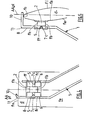
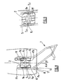
figures 1 et 2 sont deux vues en perspectives d'une précelle selon l'invention, respectivement pour l'arcade supérieure et pour l'arcade inférieure, - la
figure 3 est une vue partielle, à plus grande échelle, en perspective, d'une précelle avec un verrou orthodontique associé, - la
figure 4 est une vue en élévation, de face, d'une précelle pour l'arcade inférieure, avec un verrou orthodontique associé en situation sur une dent, - la
figure 5 est une vue, de côté, d'une précelle telle que celle de lafigure 4 , pour l'arcade inférieure, avec un verrou orthodontique associé en situation sur une dent, - la
figure 6 est une vue en élévation, de face, d'une précelle pour l'arcade supérieure, avec un verrou orthodontique associé en situation sur une dent, - la
figure 7 est une vue, de côté, d'une précelle telle que celle de lafigure 6 , pour l'arcade supérieure, avec un verrou orthodontique associé en situation sur une dent, - les
figures 8 et 9 sont deux vues en élévation de deux autres variantes de réalisation de précelle. - La précelle 1 est destinée au positionnement - et le plus souvent in fine à la solidarisation rigide (au moyen de colle ou analogue)- d'un verrou orthodontique 2 sur une dent ou un modèle de dent d. Dans l'ensemble de la description et dans les revendications le mot « dent » vise à la fois la dent d'une personne et un modèle de dent, comme cela est connu dans le domaine de l'orthodontie.
- Pour les besoins de la description, on définit, s'agissant de la dent d, son axe AA, sa face occlusale fo, ses faces interne fi et externe fe, son plan longitudinal pl (plan des
figures 4 et6 ) et son plan transversal pt (plan desfigures 5 et7 ). - Il est entendu que l'invention s'applique à toute dent - incisive, canine, prémolaire ou molaire - susceptible de recevoir un verrou orthodontique 2. Une telle dent d fait partie d'une mâchoire et appartient soit son arcade inférieure (
figures 4 et 5 ) soit à son arcade supérieure (figures 6 et 7 ). - Le verrou orthodontique 2, tant dans son ensemble que dans ses parties constitutives, peut faire l'objet de différentes variantes constructives, tant en ce qui concerne sa conception que sa réalisation.
- Un exemple de verrou orthodontique 2 auquel les précelles 1 sont bien adaptées - en l'espèce un verrou autobloquant - est décrit dans le document
WO 2006/097657 . - Pour les besoins de la description, on définit, s'agissant du verrou orthodontique 2, une face d'appui fa, à savoir la face destinée à être solidarisée contre une face correspondante fi ou fe de la dent d. En outre, le verrou 2 s'inscrit généralement dans une enveloppe de forme générale parallélépipédique ou pseudo-parallélépipédique comportant une face frontale ff opposée à la face d'appui fa, deux faces latérales respectivement haute fh et basse fb et deux faces latérales de côté fc.
- Il est entendu que les termes « inférieur », « supérieur », « haut », « bas », « vertical », « horizontal », « au-dessus », « au-dessous »... se comprennent en référence à une dent, ou une dentition, d'une personne ayant la tête droite. Mais, il est entendu que les précelles 1 comme les verrous orthodontiques 2 peuvent occuper des positions autres que celles correspondant à leur usage sur la personne considérée. Ces termes sont donc illustratifs mais non limitatifs.
- L'expression « lors de la mise en oeuvre de la précelle », parfois utilisée, correspond à la situation d'une précelle 1 qui supporte un verrou orthodontique 2 et est disposée - car portée ainsi par l'orthodontiste - de manière que le verrou orthodontique 2 soit placé contre la dent sans la position et avec l'orientation souhaités. Les termes « inférieur », « supérieur », « haut », « bas », « vertical », « horizontal », « au-dessus », « au-dessous »... se réfèrent également à cette situation, la dent ayant la position qui vient d'être indiquée.
- Le verrou orthodontique 2, dans la réalisation ici considérée, comporte également une gorge, couramment appelée slot, destinée à recevoir un arc. La gorge débouche sur la face frontale ff par une entrée de gorge allongée. La gorge débouche également sur les deux faces latérales de côté fc par des trous t.
- Dans une réalisation, le verrou orthodontique 2 comporte une première partie de base incluant la face d'appui fa et une seconde partie incluant la gorge. Le cas échéant, il est prévu une certaine angulation entre ces deux parties.
- Pour une arcade donnée, il est prévu plusieurs verrous orthodontiques 2 situés sur différentes dents - successives ou non - de l'arcade, traversés par un même arc.
- La précelle 1 comporte d'abord deux branches de manipulation 3 avec moyens élastiques, tendant à ce que, en l'absence de toute sollicitation extérieure, la précelle 1 soit fermée, ses mors 5 l'un contre l'autre.
- Les moyens élastiques sont constitués par les branches elles-mêmes qui présentent une élasticité intrinsèque.
- Les deux branches de manipulation 3 sont d'une longueur suffisante pour permettre la manipulation (déplacement, ouverture, fermeture...) par l'orthodontiste ou son personnel.
- Selon une réalisation typique, les deux branches de manipulation 3 se croisent en un point voisin des mors 5, de manière que l'on ouvre la précelle 1 en appuyant sur les branches à l'écart des mors 5.
- Les deux branches de manipulation 3 définissent un plan principal de symétrie ps, de part et d'autre duquel se trouvent chacune des deux branches de manipulation 3.
- Les deux branches de manipulation 3 sont réunies l'une à l'autre par l'une de leurs extrémités 4.
- Les deux branches de manipulation 3 sont terminées à leur autre extrémité opposée par deux mors 5, limités chacun par une face interne 6, sensiblement plane.
- Les deux faces internes 6 sont sensiblement parallèles l'une à l'autre.
- Dans la réalisation des
figures 4 à 8 , les deux faces internes 6 des mors 5 sont parallèles au plan principal de symétrie ps des deux branches de manipulation 3. - Dans la réalisation de la
figure 9 , les deux faces internes 6 des mors 5 sont inclinées d'un angle α sur le plan ps. Cette réalisation est adaptée au cas d'un verrou orthodontique 2 dont la partie incluant la gorge présente une angulation avec la partie de base incluant la face d'appui fa. L'angle α peut, par exemple, être de l'ordre de quelques degrés, plus généralement inférieur à 30°. - Les mors 5 sont destinés à la saisie du verrou orthodontique 2, en vue de son positionnement et de son orientation, et, le plus souvent in fine, de sa solidarisation, sur une dent d à l'emplacement et avec l'orientation souhaités.
- Les mors 5 ont une taille au moins sensiblement égale à celle des faces latérales de côté fc du verrou orthodontique 2, de sorte qu'ils enveloppent, au moins sensiblement, les faces latérales de côté fc du verrou orthodontique 2.
- La précelle 1 comporte deux saillies 7 dirigées l'une vers l'autre, ménagées sur les deux faces internes 6 des deux mors 5, en l'espèce dans leur partie médiane.
- En l'espèce, une saillie 7 est en forme de pion de forme générale cylindrique, et, dans la réalisation générale, de diamètre adapté à la taille du slot.
- Les deux saillies 7 sont agencées de manière à être aptes à coopérer de façon amovible, avec ajustement, avec deux creux c opposés l'un à l'autre, ménagés sur les deux faces latérales de côté fc du verrou orthodontique 2. On comprend donc que la précelle 1 implique l'emploi d'un tel type de verrou orthodontique 2.
- On entend par coopération de façon amovible et avec ajustement, le fait que le jeu entre les saillies et les creux c permet de faire pénétrer les saillies 7 dans les creux c, de les enlever, l'un et l'autre sans effort excessif, et une fois associés qu'il n'y ait pas de déplacement intempestif latéral significatif entre eux.
- La face externe des saillies 7 en forme de pions et la face interne conjuguée des creux c du verrou orthodontique 2 sont donc lisses ou du moins suffisamment lisses pour permettre l'ajustement et l'amovibilité recherchés.
- Dans les réalisations représentées, les deux saillies 7 sont coaxiales, de même que les deux creux c. Dans ce cas, il est prévu en outre une possibilité de pivotement relatif, au moins dans une certaine plage, des saillies 7 par rapport aux creux c, c'est-à-dire du verrou orthodontique 2 par rapport aux mors 5 et donc par rapport à la précelle 1. Dans cette réalisation, les sections droites transversales des saillies 7 en forme de pions et des creux c du verrou orthodontique 2 sont agencées pour permettre le pivotement recherché, notamment ces sections droites transversales - au moins l'une de deux sections conjuguées - ont une forme circulaire.
- Cette disposition constructive est avantageuse en ce qu'elle a pour effet que lorsque l'on applique fermement le verrou orthodontique 2 sur la dent d, par exemple pour sa solidarisation, la face d'appui fa du verrou orthodontique 2 est parfaitement appliquée sur la face correspondante fi ou fe de la dent d, sans risque d'écartement ou de bâillement, comme cela se révèle être le cas lorsque l'on utilise les jauges de l'état connu de la technique.
- Dans le cas des
figures 4 à 6 , les deux saillies coaxiales 7 ont un axe perpendiculaire ou sensiblement perpendiculaire aux faces internes 6 respectives des mors 5. - Dans le cas des
figures 8 et 9 , les deux saillies coaxiales 7 ont un axe incliné par rapport aux faces internes 6 respectives des mors 5 d'un angle β. L'angle β peut varier de zéro à une trentaine de degrés, selon la technique utilisée par l'orthodontiste. - La disposition constructive à saillies 7 et creux c décrite a pour fonction d'assurer un positionnement du verrou orthodontique 2 par rapport à la précelle 1 qui, abstraction faite de la possibilité de pivotement relatif précédemment mentionnée, est connu, précis, reproductible, sans risque d'erreur, et ce de façon aisée et rapide.
- Dans une réalisation, les creux c sont constitués par les trous, c'est-à-dire les parties terminales de la gorge.
- Dans une autre réalisation, les creux c sont distincts des trous.
- Le positionnement des saillies 7 sur les faces internes 6 et le positionnement des creux c sur les faces latérales de côté fc correspond à la position relative souhaitée du verrou orthodontique 2 par rapport à la précelle 1.
- La précelle 1 comporte également au moins un - et dans le cas des réalisations représentées sur les figures un seul - prolongement 8 s'étendant à partir d'une extrémité libre 9 de l'un des mors 5.
- Ce prolongement 8 s'étend, par rapport à cette extrémité libre 9, avec une angulation et sur une longueur appropriées à la fonction remplie, comme il est exposé par la suite.
- Le prolongement 8 est en effet conçu, tout d'abord, pour être apte, lors de la mise en oeuvre de la précelle 1, à s'étendre sensiblement parallèlement à l'axe AA de la dent d en direction de la face occlusale fo.
- Le prolongement 8 est conçu, ensuite, pour être apte, lors de la mise en oeuvre de la précelle 1, à ce qu'un retour 10, faisant partie de la précelle 1 et décrit par la suite, vienne en butée sur la face occlusale fo.
- En effet, la précelle 1 comporte, en outre, au moins un - et dans le cas des réalisations représentées sur les figures un seul - retour 10 s'étendant transversalement à partir d'une extrémité libre 11 du prolongement 8. Cette extrémité 11 est à l'opposé d'un chant.
- Dans les réalisations représentées sur les figures, le prolongement 8 a une forme générale de tige fine, ou une forme équivalente disposée sensiblement verticalement lors de la mise en oeuvre de la précelle 1.
- Le prolongement 8 prolonge le chant d'extrémité du mors 5 à partir de l'une de ses extrémités 9 (dépendant de la destination de la précelle comme il est exposé par la suite), le prolongement 8 et le chant étant au moins sensiblement coplanaires ou colinéaires.
- Lors de la mise en oeuvre de la précelle 1, le chant vient parallèlement à la face fi ou fe de la dent d sur laquelle le verrou orthodontique 2 est destiné à être positionné, orienté et solidarisé.
- Le retour 10 a également une forme générale de tige fine, ou une forme équivalente.
- Le prolongement 8 et le retour 10 peuvent constituer un ensemble monobloc avec le reste de la précelle 1.
- Dans le cas général, le retour 10 s'étend essentiellement dans une direction sensiblement perpendiculaire au prolongement 8 et dans le sens prolongeant les deux branches de manipulation 3, de manière que lors de la mise en oeuvre de la précelle 1, le retour 10 est au moins sensiblement orthogonal au plan longitudinal pl de la dent d, tout en étant dirigé vers la dent d, elle-même, pour pouvoir interférer avec sa face occlusale fo, par un mouvement de coulissement vertical approprié.
- Dans le cas d'une dent d pointue, on prévoit un retour 10 en forme générale de bande, ou de forme équivalente c'est-à dire s'étendant en surface, le retour 10 s'étendant ainsi non seulement dans la première direction précédemment mentionnée, mais également dans une seconde direction perpendiculaire à la première. Du fait de cette disposition constructive, lors de la mise en oeuvre de la précelle 1, le retour 10 s'étend aussi dans le plan longitudinal pl de la dent d vers son plan transversal pt et l'on est assuré que le retour 10 puisse interférer avec la dent d.
- Dans la réalisation à un seul prolongement 8 et un seul retour 10, ce prolongement 8 et ce retour 10 sont associés à l'un des deux mors 5, l'autre en étant dépourvu
- Dans une autre réalisation possible, la précelle 1 comporte deux prolongements et deux retours tels que 8 et 10. Ces deux paires d'un prolongement et d'un retour 8, 10, sont similaires. Chaque paire d'un prolongement et d'un retour 8, 10, est associée à un mors 5.
- La structure, les dimensions et les angulations de la précelle 1 sont spécialement adaptées à la dent d à laquelle elle est destinée. Tel est le cas, en particulier de la longueur du prolongement 8 qui conditionne la position verticale du verrou orthodontique 2 sur la dent d, laquelle est un paramètre conditionnant le fonctionnement de l'ensemble d'orthodontie à verrou et arc associé. Ainsi, plus le prolongement 8 est court, plus le verrou orthodontique 2 sera placé sur la dent d à proximité de la face occlusale fo. Inversement, plus le prolongement 8 est long, plus le verrou orthodontique 2 sera placé sur la dent d éloigné de la face occlusale fo.
- Préférentiellement, on prévoit pour le prolongement 8, plusieurs longueurs types correspondant à des implantations standards.
- Par ailleurs, la structure de la précelle 1 dépend de sa destination, à savoir une dent d de l'arcade inférieure ou une dent d de l'arcade supérieure de la mâchoire. En effet, les positions relatives respectives des faces occlusales fo par rapport à la précelle 1, plus spécialement aux mors 5, peuvent être qualifiées d'opposées.
- Dans le cas d'une précelle 1 spécialement destinée à l'arcade inférieure de la mâchoire (
figures 4 et 5 ), le prolongement 8 s'étend vers le haut de la précelle 1. Dans cet arrangement, le prolongement 8 est situé au dessus des saillies 7 et le retour 10 est situé au-dessus du prolongement 8, le verrou orthodontique 2 étant placé au-dessous de la face occlusale fo. - Inversement, dans le cas d'une précelle 1 spécialement destinée à l'arcade supérieure de la mâchoire (
figures 6 et 7 ), le prolongement 8 s'étend vers le bas de la précelle 1. Dans cet arrangement, le prolongement 8 est situé au dessous des saillies 7 et le retour 10 est situé au-dessous du prolongement 8, le verrou orthodontique 2 étant placé au-dessus de la face occlusale fo. - Dans l'un des cas, le prolongement 8 prolonge le chant d'extrémité du mors 5 à partir de sa première extrémité 9, tandis que dans l'autre cas, le prolongement 8 prolonge le chant d'extrémité du mors 5 à partir de sa seconde extrémité 9.
- L'invention concerne également une unité comprenant une précelle 1 et un verrou orthodontique 2 adapté, tels qu'ils ont été décrits. Une telle unité est destinée à une dent d identifiée.
- L'invention concerne également un ensemble comprenant une pluralité de telles unités, chaque unité correspondant à l'une des dents d d'une mâchoire devant recevoir un verrou orthodontique 2. L'orthodontiste a donc à sa disposition autant de précelles 1 et de verrous orthodontique 2 que dents d à équiper, chaque unité étant adaptée à la dent.
- Lors de la mise en oeuvre, ces différentes unités peuvent être préparées sur un plateau.
- Dans un procédé de mise en oeuvre d'une unité orthodontique telle qu'elle a été décrite, on part d'une situation dans laquelle on dispose d'un verrou orthodontique 2 et d'une précelle 1 adaptée au verrou 2 et à la dent d en cause.
- Puis, on positionne manuellement le verrou orthodontique 2 entre les deux mors 5 de la précelle 1.
- A cet effet, on place les saillies 7 de la précelle 1 dans les creux c du verrou orthodontique 2. Les faces internes 6 des mors 5 viennent contre les faces latérales de côté fc du verrou orthodontique 2, par l'effet des moyens élastiques sur les deux branches de manipulation 3 de la précelle 1. Par ailleurs, on dispose la face d'appui fa du verrou orthodontique 2 vers l'extrémité extérieure de la précelle 1, de façon qu'elle puisse être exposée à la dent d.
- Puis, on manipule la précelle 1 ainsi garnie du verrou orthodontique 2 afin d'amener la face d'appui fa vers la face fi ou fe de la dent d devant recevoir le verrou orthodontique 2.
- Puis, on positionne le verrou orthodontique 2 à l'emplacement souhaité sur la dent d, avec l'orientation souhaité. A cet effet, on vient mettre en butée le retour 10 de la précelle 1 sur la face occlusale fo de la dent d, moyennant un petit mouvement de coulissement vertical.
- Selon une réalisation, on assure en outre la solidarisation du verrou orthodontique 2 sur la dent d, au moyen de colle, par les techniques connues en orthodontie.
Claims (15)
- Précelle (1) de positionnement d'un verrou orthodontique (2) sur une dent (d), comportant deux branches de manipulation (3) avec moyens élastiques terminées par deux mors (5) de saisie du verrou (2) en vue de son positionnement et le plus souvent de sa solidarisation sur une dent (d) à l'emplacement et avec l'orientation souhaités, comprenant en outre:- deux saillies (7) dirigées l'une vers l'autre, ménagées sur les deux faces internes (6) des deux mors (5), aptes à coopérer de façon amovible, avec ajustement, avec deux creux (c) opposés l'un à l'autre ménagés sur les deux faces latérales (fc) du verrou (2),- au moins un prolongement (8) s'étendant à partir d'une extrémité libre (9) de l'un au moins des mors (5) avec une angulation et sur une longueur appropriées à ce que le prolongement (8) soit apte, lors de la mise en oeuvre de la précelle (1), à s'étendre sensiblement parallèlement à l'axe (AA) de la dent (d) en direction de la face occlusale (fo),- au moins un retour (10) s'étendant transversalement à partir d'une extrémité libre (11) d'au moins un prolongement (8), apte, lors de la mise en oeuvre de la précelle (1), à venir en butée sur la face occlusale (fo) de la dent (d).
- Précelle (1) selon la revendication 1, caractérisée en ce que les deux saillies (7) sont coaxiales et aptes à coopérer avec les deux creux coaxiaux (c), avec possibilité de pivotement relatif au moins dans une certaine plage.
- Précelle (1) selon l'une quelconque des revendications 1 et 2, caractérisée en ce que les deux saillies (7) sont coaxiales d'axe sensiblement perpendiculaire aux faces internes respectives (6) des mors (5).
- Précelle (1) selon l'une quelconque des revendications 1 et 2, caractérisée en ce que les deux saillies (7) sont coaxiales d'axe incliné par rapport aux faces internes respectives (6) des mors (5).
- Précelle (1) selon l'une quelconque des revendications 1 à 4, caractérisée en ce que les deux mors (5) ont deux faces internes (6) parallèles au plan de symétrie (ps) de la précelle (1).
- Précelle (1) selon l'une quelconque des revendications 1 à 4, caractériséé en ce que les deux mors (5) ont deux faces internes (6) parallèles, inclinées par rapport au plan de symétrie (ps) de la précelle (1).
- Précelle (1) selon l'une quelconque des revendications 1 à 6, caractérisée en ce que le retour (10) s'étend essentiellement dans une direction apte à se trouver au moins sensiblement orthogonal au plan longitudinal (pl) de la dent (d).
- Précelle (1) selon l'une quelconque des revendications 1 à 6, caractérisée en ce que le retour (10) s'étend dans deux directions sensiblement perpendiculaires, une première direction apte à se trouver au moins sensiblement orthogonale au plan longitudinal (pl)de la dent (d) et une seconde direction apte à se trouver au moins sensiblement dans le plan longitudinal (pl) de la dent (d) en direction de son plan transversal (pt).
- Précelle (1) selon l'une quelconque des revendications 1 à 8, caractérisée par des dimensions et des angulations spécialement adaptées à la dent (d) à laquelle elle est destinée et selon le type de technique utilisé par l'orthodontiste.
- Précelle (1) selon l'une quelconque des revendications 1 à 9, caractérisée par un seul prolongement (8) et un seul retour (10) sur l'un seulement des mors (5).
- Précelle (1) selon l'une quelconque des revendications 1 à 9, caractérisée par deux prolongements (8) et deux retours (10), un pour chaque mors (5).
- Précelle (1) selon l'une quelconque des revendications 1 à 11, caractérisée en ce qu'elle est spécialement destinée à l'arcade inférieure de la mâchoire, un prolongement (8) s'étendant à partir d'un mors (5) vers le haut.
- Précelle (1) selon l'une quelconque des revendications 1 à 11, caractérisée en ce qu'elle est spécialement destinée à l'arcade supérieure de la mâchoire, un prolongement (8) s'étendant à partir d'un mors (5) vers le bas.
- Unité comprenant une précelle (1) selon l'une quelconque des revendications 1 à 13 et un verrou orthodontique (2) ayant deux creux (c) opposés l'un à l'autre ménagés sur les deux faces latérales (fc), aptes à coopérer avec les deux saillies (7) de la précelle (1), de façon amovible et avec ajustement.
- Ensemble comprenant une pluralité d'unités selon la revendication 14, chaque unité correspondant à l'une des dents (d) devant recevoir un verrou orthodontique (2).
Applications Claiming Priority (2)
| Application Number | Priority Date | Filing Date | Title |
|---|---|---|---|
| FR0800956A FR2927795B1 (fr) | 2008-02-22 | 2008-02-22 | Precelle pour verrou orthodontique. |
| PCT/FR2009/050144 WO2009103913A1 (fr) | 2008-02-22 | 2009-01-30 | Precelle pour verrou orthodontique |
Publications (2)
| Publication Number | Publication Date |
|---|---|
| EP2249738A1 EP2249738A1 (fr) | 2010-11-17 |
| EP2249738B1 true EP2249738B1 (fr) | 2011-10-12 |
Family
ID=39709292
Family Applications (1)
| Application Number | Title | Priority Date | Filing Date |
|---|---|---|---|
| EP09713386A Not-in-force EP2249738B1 (fr) | 2008-02-22 | 2009-01-30 | Precelle pour verrou orthodontique |
Country Status (5)
| Country | Link |
|---|---|
| US (1) | US20110003263A1 (fr) |
| EP (1) | EP2249738B1 (fr) |
| AT (1) | ATE527960T1 (fr) |
| FR (1) | FR2927795B1 (fr) |
| WO (1) | WO2009103913A1 (fr) |
Families Citing this family (8)
| Publication number | Priority date | Publication date | Assignee | Title |
|---|---|---|---|---|
| AUPS259002A0 (en) * | 2002-05-27 | 2002-06-13 | Bionic Ear Institute, The | Generation of electrical stimuli for application to a cochlea |
| KR101206732B1 (ko) * | 2012-01-31 | 2012-11-30 | 김중한 | 치아 교정 브래킷 부착용 툴 |
| US20140012314A1 (en) * | 2012-06-29 | 2014-01-09 | Invivo Therapeutics Corporation | Cupped forceps |
| CO7200060A1 (es) * | 2013-08-20 | 2015-02-27 | Univ Nac De Colombia | Herramienta ortodóntica para ubicar, posicionar y adosar brackets en la superficie vestibular del diente |
| JP1561687S (fr) * | 2016-01-21 | 2016-10-31 | ||
| CN109873760B (zh) | 2017-12-01 | 2020-08-07 | 华为技术有限公司 | 处理路由的方法和装置、以及数据传输的方法和装置 |
| KR102205533B1 (ko) * | 2019-05-15 | 2021-01-19 | 이도훈 | 치열교정용 트위저 |
| KR102097757B1 (ko) * | 2020-01-16 | 2020-04-06 | 유태권 | 치아 교정용 튜브 트위저 |
Family Cites Families (10)
| Publication number | Priority date | Publication date | Assignee | Title |
|---|---|---|---|---|
| US3686762A (en) * | 1971-08-02 | 1972-08-29 | Robert E Sutter | Orthodontic applicator tool |
| US5007827A (en) * | 1989-07-11 | 1991-04-16 | Difranco Paul A | Orthodontic tweezers |
| CA2139078C (fr) * | 1993-12-23 | 1998-04-21 | James A. Nicholson | Supports orthodontiques |
| KR0163827B1 (ko) * | 1995-10-23 | 1998-12-15 | 김중한 | 게이지 일체형 트위저 |
| US5810582A (en) * | 1996-07-02 | 1998-09-22 | Doyle; Walter A. | Orthodontic bracket holding and placement apparatus |
| US6447291B2 (en) * | 1999-12-31 | 2002-09-10 | Joong Han Kim | Orthodontic jig for attaching orthodontic brackets |
| US6290495B1 (en) * | 2000-08-10 | 2001-09-18 | S. Jabri | Dental tool for installing brackets for orthodontic braces |
| US6679700B2 (en) * | 2002-01-16 | 2004-01-20 | Progressive America, Inc. | Archwire system |
| US6786719B2 (en) * | 2002-01-16 | 2004-09-07 | Progressive America, Inc. | Orthodontic bracket holder |
| US20100143856A1 (en) * | 2006-06-09 | 2010-06-10 | Gestenco International Ab | Placement jig for an orthodontic device |
-
2008
- 2008-02-22 FR FR0800956A patent/FR2927795B1/fr not_active Expired - Fee Related
-
2009
- 2009-01-30 AT AT09713386T patent/ATE527960T1/de not_active IP Right Cessation
- 2009-01-30 EP EP09713386A patent/EP2249738B1/fr not_active Not-in-force
- 2009-01-30 WO PCT/FR2009/050144 patent/WO2009103913A1/fr not_active Ceased
- 2009-01-30 US US12/918,858 patent/US20110003263A1/en not_active Abandoned
Also Published As
| Publication number | Publication date |
|---|---|
| FR2927795A1 (fr) | 2009-08-28 |
| EP2249738A1 (fr) | 2010-11-17 |
| ATE527960T1 (de) | 2011-10-15 |
| US20110003263A1 (en) | 2011-01-06 |
| WO2009103913A1 (fr) | 2009-08-27 |
| FR2927795B1 (fr) | 2010-04-09 |
Similar Documents
| Publication | Publication Date | Title |
|---|---|---|
| EP2249738B1 (fr) | Precelle pour verrou orthodontique | |
| EP1458298B1 (fr) | Ensemble pour l'osteosynthese du rachis comprenant une tete d'organe d'ancrage et un outil pour la fixation de la tete | |
| CH663349A5 (fr) | Structure de fixation dentaire. | |
| EP0151086A2 (fr) | Dispositif de préparation et de positionnement de "Dies" ou modeles positifs unitaires pour tout ou partie de l'une ou des deux arcades dentaires et de mise en occluseur ou articulateur | |
| FR2969483A1 (fr) | Ensemble forme par une attache auto-ligaturante et un clip elastique, ensemble forme par cette attache, ce clip et une base, et appareil orthodontique le comportant. | |
| FR2934769A1 (fr) | Appareil dentaire de contrainte de la langue pour corriger la macroglossie et l'apnee du sommeil. | |
| WO2010061124A1 (fr) | Dispositif d'aide a la pose d'implants dentaires | |
| EP2068726A2 (fr) | Ancillaire de visee pour resurfacage de la tete femorale | |
| CA2601109C (fr) | Dispositif de correction orthodontique | |
| EP2836155B1 (fr) | Procédé de fabrication d'un dispositif de collage d'attaches orthodontiques | |
| EP3518818B1 (fr) | Plaque mandibulaire et kit de mise en place | |
| EP4395690B1 (fr) | Implant zygomatique et kit correspondant | |
| FR2612116A1 (fr) | Chevalet | |
| FR2901994A3 (fr) | Gabarit de mise en place pour un dispositif orthodontique. | |
| EP4371523A1 (fr) | Guide chirurgical pour la pose d'implants dentaires | |
| CH677600A5 (fr) | ||
| CA3244840A1 (fr) | Device for moving an upper molar | |
| FR2710831A1 (fr) | Procédé d'orthodontie par dissociation géométrique. | |
| FR2553031A1 (fr) | Mecanisme et appareil de pliage de plaques, notamment de cliches d'impression | |
| EP0953698B1 (fr) | Bride pour associer une hampe à un mât | |
| FR2870714A1 (fr) | Outillage pour la pose d'implants dentaires | |
| FR3030223A1 (fr) | Ensemble pour la realisation d'un appareil orthodontique et procede de montage associe | |
| FR2776501A1 (fr) | Porte-empreinte d'occlusion | |
| WO2025017269A1 (fr) | Bracket orthodontique | |
| FR2924920A1 (fr) | Guide de percage pour un implant dentaire |
Legal Events
| Date | Code | Title | Description |
|---|---|---|---|
| PUAI | Public reference made under article 153(3) epc to a published international application that has entered the european phase |
Free format text: ORIGINAL CODE: 0009012 |
|
| 17P | Request for examination filed |
Effective date: 20100817 |
|
| AK | Designated contracting states |
Kind code of ref document: A1 Designated state(s): AT BE BG CH CY CZ DE DK EE ES FI FR GB GR HR HU IE IS IT LI LT LU LV MC MK MT NL NO PL PT RO SE SI SK TR |
|
| AX | Request for extension of the european patent |
Extension state: AL BA RS |
|
| GRAP | Despatch of communication of intention to grant a patent |
Free format text: ORIGINAL CODE: EPIDOSNIGR1 |
|
| DAX | Request for extension of the european patent (deleted) | ||
| GRAS | Grant fee paid |
Free format text: ORIGINAL CODE: EPIDOSNIGR3 |
|
| GRAA | (expected) grant |
Free format text: ORIGINAL CODE: 0009210 |
|
| RAP1 | Party data changed (applicant data changed or rights of an application transferred) |
Owner name: CLOR, CHARLES |
|
| RIN1 | Information on inventor provided before grant (corrected) |
Inventor name: CLOR, CHARLES |
|
| AK | Designated contracting states |
Kind code of ref document: B1 Designated state(s): AT BE BG CH CY CZ DE DK EE ES FI FR GB GR HR HU IE IS IT LI LT LU LV MC MK MT NL NO PL PT RO SE SI SK TR |
|
| REG | Reference to a national code |
Ref country code: GB Ref legal event code: FG4D Free format text: NOT ENGLISH |
|
| REG | Reference to a national code |
Ref country code: CH Ref legal event code: EP |
|
| REG | Reference to a national code |
Ref country code: IE Ref legal event code: FG4D |
|
| REG | Reference to a national code |
Ref country code: DE Ref legal event code: R096 Ref document number: 602009003052 Country of ref document: DE Effective date: 20120112 |
|
| REG | Reference to a national code |
Ref country code: NL Ref legal event code: VDEP Effective date: 20111012 |
|
| LTIE | Lt: invalidation of european patent or patent extension |
Effective date: 20111012 |
|
| REG | Reference to a national code |
Ref country code: AT Ref legal event code: MK05 Ref document number: 527960 Country of ref document: AT Kind code of ref document: T Effective date: 20111012 |
|
| PG25 | Lapsed in a contracting state [announced via postgrant information from national office to epo] |
Ref country code: NO Free format text: LAPSE BECAUSE OF FAILURE TO SUBMIT A TRANSLATION OF THE DESCRIPTION OR TO PAY THE FEE WITHIN THE PRESCRIBED TIME-LIMIT Effective date: 20120112 Ref country code: IS Free format text: LAPSE BECAUSE OF FAILURE TO SUBMIT A TRANSLATION OF THE DESCRIPTION OR TO PAY THE FEE WITHIN THE PRESCRIBED TIME-LIMIT Effective date: 20120212 Ref country code: LT Free format text: LAPSE BECAUSE OF FAILURE TO SUBMIT A TRANSLATION OF THE DESCRIPTION OR TO PAY THE FEE WITHIN THE PRESCRIBED TIME-LIMIT Effective date: 20111012 |
|
| REG | Reference to a national code |
Ref country code: IE Ref legal event code: FD4D |
|
| PG25 | Lapsed in a contracting state [announced via postgrant information from national office to epo] |
Ref country code: SE Free format text: LAPSE BECAUSE OF FAILURE TO SUBMIT A TRANSLATION OF THE DESCRIPTION OR TO PAY THE FEE WITHIN THE PRESCRIBED TIME-LIMIT Effective date: 20111012 Ref country code: SI Free format text: LAPSE BECAUSE OF FAILURE TO SUBMIT A TRANSLATION OF THE DESCRIPTION OR TO PAY THE FEE WITHIN THE PRESCRIBED TIME-LIMIT Effective date: 20111012 Ref country code: PT Free format text: LAPSE BECAUSE OF FAILURE TO SUBMIT A TRANSLATION OF THE DESCRIPTION OR TO PAY THE FEE WITHIN THE PRESCRIBED TIME-LIMIT Effective date: 20120213 Ref country code: GR Free format text: LAPSE BECAUSE OF FAILURE TO SUBMIT A TRANSLATION OF THE DESCRIPTION OR TO PAY THE FEE WITHIN THE PRESCRIBED TIME-LIMIT Effective date: 20120113 Ref country code: LV Free format text: LAPSE BECAUSE OF FAILURE TO SUBMIT A TRANSLATION OF THE DESCRIPTION OR TO PAY THE FEE WITHIN THE PRESCRIBED TIME-LIMIT Effective date: 20111012 Ref country code: NL Free format text: LAPSE BECAUSE OF FAILURE TO SUBMIT A TRANSLATION OF THE DESCRIPTION OR TO PAY THE FEE WITHIN THE PRESCRIBED TIME-LIMIT Effective date: 20111012 Ref country code: HR Free format text: LAPSE BECAUSE OF FAILURE TO SUBMIT A TRANSLATION OF THE DESCRIPTION OR TO PAY THE FEE WITHIN THE PRESCRIBED TIME-LIMIT Effective date: 20111012 |
|
| PG25 | Lapsed in a contracting state [announced via postgrant information from national office to epo] |
Ref country code: CY Free format text: LAPSE BECAUSE OF FAILURE TO SUBMIT A TRANSLATION OF THE DESCRIPTION OR TO PAY THE FEE WITHIN THE PRESCRIBED TIME-LIMIT Effective date: 20111012 |
|
| BERE | Be: lapsed |
Owner name: CLOR, CHARLES Effective date: 20120131 |
|
| PG25 | Lapsed in a contracting state [announced via postgrant information from national office to epo] |
Ref country code: EE Free format text: LAPSE BECAUSE OF FAILURE TO SUBMIT A TRANSLATION OF THE DESCRIPTION OR TO PAY THE FEE WITHIN THE PRESCRIBED TIME-LIMIT Effective date: 20111012 Ref country code: CZ Free format text: LAPSE BECAUSE OF FAILURE TO SUBMIT A TRANSLATION OF THE DESCRIPTION OR TO PAY THE FEE WITHIN THE PRESCRIBED TIME-LIMIT Effective date: 20111012 Ref country code: BG Free format text: LAPSE BECAUSE OF FAILURE TO SUBMIT A TRANSLATION OF THE DESCRIPTION OR TO PAY THE FEE WITHIN THE PRESCRIBED TIME-LIMIT Effective date: 20120112 Ref country code: IE Free format text: LAPSE BECAUSE OF FAILURE TO SUBMIT A TRANSLATION OF THE DESCRIPTION OR TO PAY THE FEE WITHIN THE PRESCRIBED TIME-LIMIT Effective date: 20111012 Ref country code: SK Free format text: LAPSE BECAUSE OF FAILURE TO SUBMIT A TRANSLATION OF THE DESCRIPTION OR TO PAY THE FEE WITHIN THE PRESCRIBED TIME-LIMIT Effective date: 20111012 Ref country code: DK Free format text: LAPSE BECAUSE OF FAILURE TO SUBMIT A TRANSLATION OF THE DESCRIPTION OR TO PAY THE FEE WITHIN THE PRESCRIBED TIME-LIMIT Effective date: 20111012 |
|
| PLBE | No opposition filed within time limit |
Free format text: ORIGINAL CODE: 0009261 |
|
| STAA | Information on the status of an ep patent application or granted ep patent |
Free format text: STATUS: NO OPPOSITION FILED WITHIN TIME LIMIT |
|
| PG25 | Lapsed in a contracting state [announced via postgrant information from national office to epo] |
Ref country code: IT Free format text: LAPSE BECAUSE OF FAILURE TO SUBMIT A TRANSLATION OF THE DESCRIPTION OR TO PAY THE FEE WITHIN THE PRESCRIBED TIME-LIMIT Effective date: 20111012 Ref country code: MC Free format text: LAPSE BECAUSE OF NON-PAYMENT OF DUE FEES Effective date: 20120131 Ref country code: PL Free format text: LAPSE BECAUSE OF FAILURE TO SUBMIT A TRANSLATION OF THE DESCRIPTION OR TO PAY THE FEE WITHIN THE PRESCRIBED TIME-LIMIT Effective date: 20111012 Ref country code: RO Free format text: LAPSE BECAUSE OF FAILURE TO SUBMIT A TRANSLATION OF THE DESCRIPTION OR TO PAY THE FEE WITHIN THE PRESCRIBED TIME-LIMIT Effective date: 20111012 |
|
| 26N | No opposition filed |
Effective date: 20120713 |
|
| PG25 | Lapsed in a contracting state [announced via postgrant information from national office to epo] |
Ref country code: DE Free format text: LAPSE BECAUSE OF NON-PAYMENT OF DUE FEES Effective date: 20120801 |
|
| REG | Reference to a national code |
Ref country code: DE Ref legal event code: R097 Ref document number: 602009003052 Country of ref document: DE Effective date: 20120713 |
|
| REG | Reference to a national code |
Ref country code: DE Ref legal event code: R119 Ref document number: 602009003052 Country of ref document: DE Effective date: 20120801 |
|
| PG25 | Lapsed in a contracting state [announced via postgrant information from national office to epo] |
Ref country code: BE Free format text: LAPSE BECAUSE OF NON-PAYMENT OF DUE FEES Effective date: 20120131 |
|
| PG25 | Lapsed in a contracting state [announced via postgrant information from national office to epo] |
Ref country code: AT Free format text: LAPSE BECAUSE OF FAILURE TO SUBMIT A TRANSLATION OF THE DESCRIPTION OR TO PAY THE FEE WITHIN THE PRESCRIBED TIME-LIMIT Effective date: 20111012 |
|
| PG25 | Lapsed in a contracting state [announced via postgrant information from national office to epo] |
Ref country code: MK Free format text: LAPSE BECAUSE OF FAILURE TO SUBMIT A TRANSLATION OF THE DESCRIPTION OR TO PAY THE FEE WITHIN THE PRESCRIBED TIME-LIMIT Effective date: 20111012 |
|
| PG25 | Lapsed in a contracting state [announced via postgrant information from national office to epo] |
Ref country code: ES Free format text: LAPSE BECAUSE OF FAILURE TO SUBMIT A TRANSLATION OF THE DESCRIPTION OR TO PAY THE FEE WITHIN THE PRESCRIBED TIME-LIMIT Effective date: 20120123 |
|
| PG25 | Lapsed in a contracting state [announced via postgrant information from national office to epo] |
Ref country code: FI Free format text: LAPSE BECAUSE OF FAILURE TO SUBMIT A TRANSLATION OF THE DESCRIPTION OR TO PAY THE FEE WITHIN THE PRESCRIBED TIME-LIMIT Effective date: 20111012 |
|
| PG25 | Lapsed in a contracting state [announced via postgrant information from national office to epo] |
Ref country code: MT Free format text: LAPSE BECAUSE OF FAILURE TO SUBMIT A TRANSLATION OF THE DESCRIPTION OR TO PAY THE FEE WITHIN THE PRESCRIBED TIME-LIMIT Effective date: 20111012 |
|
| REG | Reference to a national code |
Ref country code: CH Ref legal event code: PL |
|
| GBPC | Gb: european patent ceased through non-payment of renewal fee |
Effective date: 20130130 |
|
| PG25 | Lapsed in a contracting state [announced via postgrant information from national office to epo] |
Ref country code: CH Free format text: LAPSE BECAUSE OF NON-PAYMENT OF DUE FEES Effective date: 20130131 Ref country code: LI Free format text: LAPSE BECAUSE OF NON-PAYMENT OF DUE FEES Effective date: 20130131 |
|
| PG25 | Lapsed in a contracting state [announced via postgrant information from national office to epo] |
Ref country code: GB Free format text: LAPSE BECAUSE OF NON-PAYMENT OF DUE FEES Effective date: 20130130 |
|
| PG25 | Lapsed in a contracting state [announced via postgrant information from national office to epo] |
Ref country code: TR Free format text: LAPSE BECAUSE OF FAILURE TO SUBMIT A TRANSLATION OF THE DESCRIPTION OR TO PAY THE FEE WITHIN THE PRESCRIBED TIME-LIMIT Effective date: 20111012 |
|
| PG25 | Lapsed in a contracting state [announced via postgrant information from national office to epo] |
Ref country code: LU Free format text: LAPSE BECAUSE OF NON-PAYMENT OF DUE FEES Effective date: 20120130 |
|
| PG25 | Lapsed in a contracting state [announced via postgrant information from national office to epo] |
Ref country code: HU Free format text: LAPSE BECAUSE OF FAILURE TO SUBMIT A TRANSLATION OF THE DESCRIPTION OR TO PAY THE FEE WITHIN THE PRESCRIBED TIME-LIMIT Effective date: 20090130 |
|
| REG | Reference to a national code |
Ref country code: FR Ref legal event code: PLFP Year of fee payment: 7 |
|
| PGFP | Annual fee paid to national office [announced via postgrant information from national office to epo] |
Ref country code: FR Payment date: 20150731 Year of fee payment: 7 |
|
| REG | Reference to a national code |
Ref country code: FR Ref legal event code: ST Effective date: 20160930 |
|
| PG25 | Lapsed in a contracting state [announced via postgrant information from national office to epo] |
Ref country code: FR Free format text: LAPSE BECAUSE OF NON-PAYMENT OF DUE FEES Effective date: 20160201 |