EP2249740B1 - Implant dentaire et son procédé de fabrication - Google Patents
Implant dentaire et son procédé de fabrication Download PDFInfo
- Publication number
- EP2249740B1 EP2249740B1 EP09714335A EP09714335A EP2249740B1 EP 2249740 B1 EP2249740 B1 EP 2249740B1 EP 09714335 A EP09714335 A EP 09714335A EP 09714335 A EP09714335 A EP 09714335A EP 2249740 B1 EP2249740 B1 EP 2249740B1
- Authority
- EP
- European Patent Office
- Prior art keywords
- base
- neck
- dental implant
- implant according
- abutment
- Prior art date
- Legal status (The legal status is an assumption and is not a legal conclusion. Google has not performed a legal analysis and makes no representation as to the accuracy of the status listed.)
- Not-in-force
Links
- 238000004519 manufacturing process Methods 0.000 title claims description 5
- 239000007943 implant Substances 0.000 title description 30
- 239000004053 dental implant Substances 0.000 claims description 27
- 238000005530 etching Methods 0.000 claims description 15
- KWYUFKZDYYNOTN-UHFFFAOYSA-M Potassium hydroxide Chemical compound [OH-].[K+] KWYUFKZDYYNOTN-UHFFFAOYSA-M 0.000 claims description 12
- 238000000034 method Methods 0.000 claims description 10
- 238000005422 blasting Methods 0.000 claims description 7
- 229910001069 Ti alloy Inorganic materials 0.000 claims description 5
- RTAQQCXQSZGOHL-UHFFFAOYSA-N Titanium Chemical compound [Ti] RTAQQCXQSZGOHL-UHFFFAOYSA-N 0.000 claims description 5
- 229910052719 titanium Inorganic materials 0.000 claims description 5
- 239000010936 titanium Substances 0.000 claims description 5
- 239000003795 chemical substances by application Substances 0.000 claims description 4
- 229910052751 metal Inorganic materials 0.000 claims description 2
- 239000002184 metal Substances 0.000 claims description 2
- 229910001092 metal group alloy Inorganic materials 0.000 claims description 2
- RVTZCBVAJQQJTK-UHFFFAOYSA-N oxygen(2-);zirconium(4+) Chemical compound [O-2].[O-2].[Zr+4] RVTZCBVAJQQJTK-UHFFFAOYSA-N 0.000 claims description 2
- 229910001928 zirconium oxide Inorganic materials 0.000 claims description 2
- 210000001519 tissue Anatomy 0.000 description 22
- 210000000988 bone and bone Anatomy 0.000 description 16
- 238000003780 insertion Methods 0.000 description 12
- 230000037431 insertion Effects 0.000 description 12
- 230000012010 growth Effects 0.000 description 11
- 230000003993 interaction Effects 0.000 description 10
- 230000003746 surface roughness Effects 0.000 description 9
- 238000003801 milling Methods 0.000 description 8
- 238000013461 design Methods 0.000 description 7
- 210000002919 epithelial cell Anatomy 0.000 description 7
- 239000000463 material Substances 0.000 description 7
- 241000894006 Bacteria Species 0.000 description 6
- 241000245772 Gasteria Species 0.000 description 6
- 238000010276 construction Methods 0.000 description 6
- 238000005259 measurement Methods 0.000 description 6
- 210000004027 cell Anatomy 0.000 description 4
- 238000009826 distribution Methods 0.000 description 4
- 210000000963 osteoblast Anatomy 0.000 description 4
- 230000007704 transition Effects 0.000 description 4
- HEMHJVSKTPXQMS-UHFFFAOYSA-M Sodium hydroxide Chemical compound [OH-].[Na+] HEMHJVSKTPXQMS-UHFFFAOYSA-M 0.000 description 3
- 229910052593 corundum Inorganic materials 0.000 description 3
- 239000010431 corundum Substances 0.000 description 3
- 238000011161 development Methods 0.000 description 3
- 230000000694 effects Effects 0.000 description 3
- 210000002950 fibroblast Anatomy 0.000 description 3
- NJPPVKZQTLUDBO-UHFFFAOYSA-N novaluron Chemical compound C1=C(Cl)C(OC(F)(F)C(OC(F)(F)F)F)=CC=C1NC(=O)NC(=O)C1=C(F)C=CC=C1F NJPPVKZQTLUDBO-UHFFFAOYSA-N 0.000 description 3
- 238000010079 rubber tapping Methods 0.000 description 3
- 238000013519 translation Methods 0.000 description 3
- 230000006978 adaptation Effects 0.000 description 2
- 230000015572 biosynthetic process Effects 0.000 description 2
- 210000002449 bone cell Anatomy 0.000 description 2
- 230000010261 cell growth Effects 0.000 description 2
- 210000002808 connective tissue Anatomy 0.000 description 2
- 239000004744 fabric Substances 0.000 description 2
- 239000011521 glass Substances 0.000 description 2
- 239000004576 sand Substances 0.000 description 2
- 239000002253 acid Substances 0.000 description 1
- 230000002730 additional effect Effects 0.000 description 1
- 239000000853 adhesive Substances 0.000 description 1
- 230000001070 adhesive effect Effects 0.000 description 1
- 238000013459 approach Methods 0.000 description 1
- 230000008952 bacterial invasion Effects 0.000 description 1
- 239000011324 bead Substances 0.000 description 1
- 239000012620 biological material Substances 0.000 description 1
- 239000008280 blood Substances 0.000 description 1
- 210000004369 blood Anatomy 0.000 description 1
- 238000012512 characterization method Methods 0.000 description 1
- 230000001886 ciliary effect Effects 0.000 description 1
- 239000000470 constituent Substances 0.000 description 1
- 230000008094 contradictory effect Effects 0.000 description 1
- 238000005520 cutting process Methods 0.000 description 1
- 230000007423 decrease Effects 0.000 description 1
- 230000001419 dependent effect Effects 0.000 description 1
- 238000005516 engineering process Methods 0.000 description 1
- 210000000981 epithelium Anatomy 0.000 description 1
- 230000002349 favourable effect Effects 0.000 description 1
- 238000000338 in vitro Methods 0.000 description 1
- 238000011534 incubation Methods 0.000 description 1
- 230000002401 inhibitory effect Effects 0.000 description 1
- 238000009434 installation Methods 0.000 description 1
- 238000005457 optimization Methods 0.000 description 1
- 230000002188 osteogenic effect Effects 0.000 description 1
- 239000002245 particle Substances 0.000 description 1
- 230000035515 penetration Effects 0.000 description 1
- 230000008092 positive effect Effects 0.000 description 1
- 210000000332 tooth crown Anatomy 0.000 description 1
- 238000003466 welding Methods 0.000 description 1
- 238000009736 wetting Methods 0.000 description 1
- 230000029663 wound healing Effects 0.000 description 1
Images



Classifications
-
- A—HUMAN NECESSITIES
- A61—MEDICAL OR VETERINARY SCIENCE; HYGIENE
- A61C—DENTISTRY; APPARATUS OR METHODS FOR ORAL OR DENTAL HYGIENE
- A61C8/00—Means to be fixed to the jaw-bone for consolidating natural teeth or for fixing dental prostheses thereon; Dental implants; Implanting tools
- A61C8/0018—Means to be fixed to the jaw-bone for consolidating natural teeth or for fixing dental prostheses thereon; Dental implants; Implanting tools characterised by the shape
- A61C8/0022—Self-screwing
-
- A—HUMAN NECESSITIES
- A61—MEDICAL OR VETERINARY SCIENCE; HYGIENE
- A61C—DENTISTRY; APPARATUS OR METHODS FOR ORAL OR DENTAL HYGIENE
- A61C8/00—Means to be fixed to the jaw-bone for consolidating natural teeth or for fixing dental prostheses thereon; Dental implants; Implanting tools
- A61C8/0048—Connecting the upper structure to the implant, e.g. bridging bars
- A61C8/005—Connecting devices for joining an upper structure with an implant member, e.g. spacers
-
- A—HUMAN NECESSITIES
- A61—MEDICAL OR VETERINARY SCIENCE; HYGIENE
- A61C—DENTISTRY; APPARATUS OR METHODS FOR ORAL OR DENTAL HYGIENE
- A61C8/00—Means to be fixed to the jaw-bone for consolidating natural teeth or for fixing dental prostheses thereon; Dental implants; Implanting tools
- A61C8/0048—Connecting the upper structure to the implant, e.g. bridging bars
- A61C8/005—Connecting devices for joining an upper structure with an implant member, e.g. spacers
- A61C8/0066—Connecting devices for joining an upper structure with an implant member, e.g. spacers with positioning means
-
- A—HUMAN NECESSITIES
- A61—MEDICAL OR VETERINARY SCIENCE; HYGIENE
- A61C—DENTISTRY; APPARATUS OR METHODS FOR ORAL OR DENTAL HYGIENE
- A61C8/00—Means to be fixed to the jaw-bone for consolidating natural teeth or for fixing dental prostheses thereon; Dental implants; Implanting tools
- A61C8/0048—Connecting the upper structure to the implant, e.g. bridging bars
- A61C8/0077—Connecting the upper structure to the implant, e.g. bridging bars with shape following the gingival surface or the bone surface
-
- A—HUMAN NECESSITIES
- A61—MEDICAL OR VETERINARY SCIENCE; HYGIENE
- A61C—DENTISTRY; APPARATUS OR METHODS FOR ORAL OR DENTAL HYGIENE
- A61C8/00—Means to be fixed to the jaw-bone for consolidating natural teeth or for fixing dental prostheses thereon; Dental implants; Implanting tools
- A61C8/0018—Means to be fixed to the jaw-bone for consolidating natural teeth or for fixing dental prostheses thereon; Dental implants; Implanting tools characterised by the shape
- A61C8/0037—Details of the shape
- A61C2008/0046—Textured surface, e.g. roughness, microstructure
-
- A—HUMAN NECESSITIES
- A61—MEDICAL OR VETERINARY SCIENCE; HYGIENE
- A61C—DENTISTRY; APPARATUS OR METHODS FOR ORAL OR DENTAL HYGIENE
- A61C8/00—Means to be fixed to the jaw-bone for consolidating natural teeth or for fixing dental prostheses thereon; Dental implants; Implanting tools
- A61C8/0048—Connecting the upper structure to the implant, e.g. bridging bars
- A61C8/005—Connecting devices for joining an upper structure with an implant member, e.g. spacers
- A61C8/006—Connecting devices for joining an upper structure with an implant member, e.g. spacers with polygonal positional means, e.g. hexagonal or octagonal
-
- A—HUMAN NECESSITIES
- A61—MEDICAL OR VETERINARY SCIENCE; HYGIENE
- A61C—DENTISTRY; APPARATUS OR METHODS FOR ORAL OR DENTAL HYGIENE
- A61C8/00—Means to be fixed to the jaw-bone for consolidating natural teeth or for fixing dental prostheses thereon; Dental implants; Implanting tools
- A61C8/0048—Connecting the upper structure to the implant, e.g. bridging bars
- A61C8/005—Connecting devices for joining an upper structure with an implant member, e.g. spacers
- A61C8/0069—Connecting devices for joining an upper structure with an implant member, e.g. spacers tapered or conical connection
-
- A—HUMAN NECESSITIES
- A61—MEDICAL OR VETERINARY SCIENCE; HYGIENE
- A61C—DENTISTRY; APPARATUS OR METHODS FOR ORAL OR DENTAL HYGIENE
- A61C8/00—Means to be fixed to the jaw-bone for consolidating natural teeth or for fixing dental prostheses thereon; Dental implants; Implanting tools
- A61C8/0048—Connecting the upper structure to the implant, e.g. bridging bars
- A61C8/005—Connecting devices for joining an upper structure with an implant member, e.g. spacers
- A61C8/0069—Connecting devices for joining an upper structure with an implant member, e.g. spacers tapered or conical connection
- A61C8/0072—Connecting devices for joining an upper structure with an implant member, e.g. spacers tapered or conical connection including male and female conical parts with different angles
Definitions
- the invention relates to a dental implant, comprising a base insertable into a jawbone bone with an apical body and a coronal neck whose outer surfaces each have a surface microstructure of predetermined roughness, the mean surface roughness value being greater than the value of mean roughness of the neck surface.
- the invention further relates to a method for producing a dental implant socket.
- Such dental implants are known from the DE 60 2004 007 427 T2 (German translation of the EP 1 477 141 B1 ).
- the dental implant always comprises a base, which is at least partially inserted into the jawbone.
- the pedestal is subdivided into two axial regions.
- a first area, called a body, is essentially completely inserted into the jawbone in its intended end position.
- a coronal adjoining second region, called the neck protrudes in the intended end position substantially completely beyond the jawbone and is surrounded by gum tissue.
- Coronal of the socket typically employs a structure that extends substantially completely beyond the gum tissue.
- the structure serves as the core of a crown to be attached to it.
- the structure may be formed integrally with the base or as a separate component, which is screwed or glued to the base, for example.
- the outer surface of the body is often provided with a possibly self-tapping thread with which the base is screwed into a predrilled recess in the jawbone.
- a permanent fixation of the implant depends substantially on the interaction between the biological material, ie bone and / or gum tissue, beyond the prefixing with the base surface.
- the biocompatibility of the base material is important.
- bases made of titanium or titanium alloys have proven themselves.
- the surface structure of the base is of considerable importance. In this regard, a variety of studies have been and are being carried out, sometimes with contradictory results. There is agreement that microstructuring of the surface can have positive effects.
- the DE 695 33 448 T2 (German translation of the EP 0 794 745 B1 ) suggests the formation of a uniform surface roughness for the body and neck of the implant socket.
- the generic DE 60 2004 007 427 T2 On the other hand, it takes into account the different tissue properties of bone material and gingival tissue and thus suggests a different surface roughness for the body area and the neck area of the base. In particular, it is proposed to set the surface roughness of the body to one to three micrometers by an etching method, whereas the surface of the neck is to be made "relatively smooth".
- the proposed roughness values according to the invention are the result of a complex, experimentally verified balance between the optimization of each surface for the interaction with the respectively associated tissue type on the one hand and the compatibility of the surface with the other tissue type on the other hand.
- this sub-optimal design of each surface area with respect to the respectively associated tissue overall leads to an improved durability of the implant, since the resulting, significantly improved Interaction in the critical transition region between bone and gums overcompensating effect. It seems that in the case of implants according to the state of the art, the incompatibilities of the surfaces optimized for one type of tissue with the respective other type of tissue have hitherto underestimated negative influences on the overall durability of the implant. In any case, no such reports are known.
- the invention is the result of a hitherto nowhere pursued, more holistic approach.
- the roughness values according to the invention can be achieved in any desired manner.
- it has proven to be efficient to render the surface microstructure of the body surface hard by blasting Blasting agent, such as sand or corundum, and a subsequent etching process and to produce the surface microstructure of the neck surface by an etching process.
- the etching is preferably carried out with a basic etchant, in particular an etchant containing a high concentration of potassium hydroxide.
- a basic etchant in particular an etchant containing a high concentration of potassium hydroxide.
- Such an etching method is known from DE 603 01 796 T2 (German translation of the EP 1 515 759 B1 ), which, however, deals with the multilayer structure of a dental implant socket.
- the base preferably consists essentially of metal or a metal alloy, in particular of titanium or a titanium alloy.
- the body preferably carries a macroscopic external thread structure.
- This can, as known from the prior art, screw into a prefabricated recess in the jawbone and represents a positive mechanical fixation of the base, which allows an increase of the tissue on the inventively designed base surface.
- Favorable here are self-tapping threaded structures.
- the neck has a circumferential annular groove.
- the annular groove advantageously carries a circular segment-shaped cross section with a radius of 0.2 to 0.3 millimeters, in particular of about 2.5 millimeters.
- Such an annular groove improves the growth of desired tissue on the Base surface.
- a common problem in the growth are namely fast-growing epithelial cells, which grow along the base surface from coronal to apical and thus hinder or prevent the onset of gums on the neck of the base or very extensive epithelial cell growth and the growth of bone cells on the body surface.
- the slower growing gum cells gain sufficient time to grow in the neck before the epithelial cells overgrow these areas. There is no longer any danger of the apical areas being overgrown by the epithelial cells, so that the even slower growing bone cells have sufficient time to grow in the body area of the base.
- An additional effect of the advantageous annular groove is the enlargement of the interaction surface compared to a substantially cylindrical base neck. This increases the overall force with which the implant is held in the tissue.
- the connective tissue which has grown into the annular groove constitutes a seal in the manner of an O-ring, which offers good protection against the penetration of undesired dirt particles. It should be noted that the formation of the annular groove is not necessarily coupled to the surface roughness distribution according to the invention. Rather, it is also possible to significantly improve implants with other roughness distributions of their base surface by the illustrated annular groove.
- the pedestal is substantially hollow and has an insertion area for a corresponding connection area of the structure.
- the connection between the body and socket often takes place through a screw passing through the structure and screwed into an internal thread of the socket. This inevitably results in permanent cavities in the base interior. It is of particular importance that these cavities are sealed gas and bacteria impermeable.
- a critical zone is the contact zone between the receiving opening of the base and the insertion of the structure.
- a structure which is used with a conical connection region in a receiving area of the hollow internally formed base, wherein the conical connection region with a conical taper angle conical having an apical tapered outer surface, the receiving area in the coronal area of the neck has a tapered to a socket opening angle to the inner surface tapered and the cone angle is 20 to 60 minutes of arc greater than the base opening angle.
- the absolute amount of the socket opening angle and the construction cone angle is preferably 15 degrees to 25 degrees, preferably about 20 degrees.
- the build-up cone angle is therefore slightly blunter than the socket opening angle.
- titanium, titanium alloys and zirconium oxide As an essential material for the structure, titanium, titanium alloys and zirconium oxide have been proven.
- a major problem with two-piece dental implants is the achievement of an anti-rotation of the structure relative to the base on the one hand and precise alignment of the structure relative to the base on the other.
- the structure has apical of the conical connection region a non-rotationally symmetrical Vermosterrorismvorsprung, which is positively inserted into a corresponding Vermosterrorismausappelung the base.
- the Vernstoffvorsprung and the corresponding Vermosstoffausappelung preferably have axially aligned walls.
- the anti-rotation projection and the corresponding anti-rotation recess are formed several times in a multi-axis or multiple rotation-inversion-symmetrical manner.
- the former case occurs, for example, in uniform, even-numbered polygon or star shapes
- the second case for example, in uniform, odd-numbered polygon or star shapes as a profile of the Vercardvorsprungs and the Verfterrorismaus Principleung on.
- Verreschschsch are basically from the DE 600 022 35 T2 known.
- a high-order symmetry should be realized. Preference is given to 12-fold veiled, star or cloverleaf shapes.
- the alignment of the structure and base to each other plays no or only a minor role.
- a coronal structure adjoining the neck is included, which is connected in one piece with the base.
- the cohesive connection can be done for example by a cementitious adhesive or welding.
- optimum tightness against gas and bacteria is ensured.
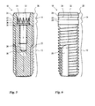
- FIGS. 1 to 4 show various representations of a preferred embodiment of an implant base according to the invention 10.
- the base 10 comprises an apically located body 12 and a coronal thereto adjoining neck 14.
- the body 12 is substantially surrounded by bone tissue, while the neck 14 is substantially surrounded by gingival tissue.
- the base body 12 is divided into two sections, namely a coronal, substantially cylindrical portion 16 and an apically thereto, conically in and radius expiring portion 18.
- Both sections 16, 18, carry a Hereins, macroscopic external thread whose depth decreases toward the apex of the cone in the conical section 18 and runs to zero.
- the thread serves to mechanically pre-fix the base in a recess drilled prior to insertion into the jawbone.
- the thread is preferably self-tapping, so that screwing into a bone recess with straight borehole walls is possible.
- the embodiment shown carries an axially extending and a right angle with a radial direction engaging milling edge 20, the depth of which corresponds approximately to the thread depth.
- the milling edge 20 extends over the entire threaded portion of the conical portion 18 and protrudes coronal beyond this slightly into the cylindrical portion 16 out.
- Such a milling edge 20, which does not carry the macroscopic thread structure, has proven to be an advantageous interaction surface with the bone tissue and improves the growth behavior, so that a firmer ingrowth of the base 10 is achieved in the jawbone.
- two such Fräskanten 20 which face each other point-symmetrical to the center of the cross-sectional plane of the base.
- milling edges 20 may be provided.
- the rectangular configuration of the milling edges 20 is not absolutely necessary, although advantageous in terms of manufacturing technology.
- the angled configuration of the milling edge 20 has in comparison to a basically also possible milling edge along a continuous chord (relative to the cross section) the advantage of a more efficient protection against rotational and radial translational forces acting on the ingrown base 10.
- the neck 14 of the illustrated embodiment of the implant base 10 is substantially cylindrical in its apical region and has an annular groove 22 interrupting the cylindrical surface.
- the annular groove 22 adjacent cylindrical portions 24 of the neck 14 in about the same width, which in turn corresponds to the width of the annular groove 22 approximately.
- the neck 14 in the ingrown state is substantially surrounded by gingival tissue.
- the gingival tissue also grows the annular groove 22 and forms an effective seal in the manner of an O-ring.
- edges of the annular groove 22 act at the junctions to the cylindrical regions 24 growth inhibiting epithelial cells, which can typically grow very quickly from coronal to apical along the outer wall of the base 10 and the growth of slower growing gum tissue cells in the neck 14th and possibly obstruct bone tissue cells in the region of the body 12.
- this carries a chamfer 26, with which the coronal end of the neck 14 is tapered. This achieves a better contour adaptation to a fitting on the base structure, the below in connection with FIG. 7 will be described in more detail.
- the base 10 is substantially hollow, as in particular from the sectional view of FIG. 1 is apparent.
- the apical region of the inner recess of the base 10 is formed as a blind bore 28 with an internal thread 30.
- This internal thread 30 is used in connection with below FIG. 7 to be described sterfix réelle the structure.
- Coronal to the blind bore 28 is followed by a receiving area 32 for the construction, wherein the receiving area 32 is divided into two sections.
- a coronal section 34 which serves as an insertion area for the structure, is formed substantially in the shape of an apical hollow cone, while the apical section 36, which serves as anti-twist protection for the structure, has a straight wall which carries projections extending the hollow conical surface.
- the resulting non-rotationally symmetric structure is well recognizable, which in the embodiment shown is in the form of a 12-beam star.
- This structure serves as related below FIG. 7 is explained in more detail, the rotation of the structure.
- the receiving area 32 is also at its narrowest point, ie its apical boundary, wider than the adjacent blind hole 28, so that a shoulder 38 is formed.
- the shoulder 38 serves as a stop surface for the structure to be described below.
- the in the Figures 1 and 2 recognizable macroscopic surface structure of the base 10 is superimposed on a not recognizable in the figures and in principle independent of the macroscopic structure advantageously usable microstructure.
- This microstructure can be characterized in particular according to its roughness values.
- the so-called RA value according to DIN EN ISO 4287 which corresponds to the arithmetic mean roughness, can be used in particular.
- AFM atomic force microscope
- the body 12 of the base 10 is coated with a hard abrasive such as sand, glass beads or corundum of appropriate size until an RA value is reached the ultimately desired RA value is blasted.
- the entire base 10 is subjected to a basic etching treatment with a basic etchant containing a high concentration of potassium hydroxide and basically from the DE 603 01 796 T2 is known, subject.
- the etching is carried out until the neck 14 and body 12 of the base 10 have reached the desired roughness values of their surfaces.
- a machined implant neck and corundum blasted body are treated with 1 mol / l NaOH + 2% H 2 O 2 at 80 ° C for 10 minutes followed by acid etching at 98 ° C for 1 hour.
- the difference in roughness between the neck and body allows selective growth of fibroblasts in the neck area and osteoblasts in the body area.
- the neck surface also has good osteogenic properties, so that in the area of the bone / gingival transition even at non-straight bone level, good growth of the osteoblasts can occur. This one is smooth Neck surfaces not possible.
- the thus reduced adhesion of desired cell types can lead to an increased growth rate of epithelial cells, which then form a long ciliary epithelium along the neck to the junction between the neck and the body. This area is then sensitive to bacterial invasion (perimplantitis). Preventing the epithelial deep growth by a tight connective tissue cuff in the neck area, which is made possible by the inventive design of the surfaces of the neck and body, prevents bone perforations.
- FIGS. 5 and 6 represent different views of a second embodiment of a base 10 according to the invention.
- the total body 12 is substantially cylindrical and carries a continuous thread.
- the reference numerals in the FIGS. 5 and 6 were taken over.
- the assembly 40 includes a substantially hollow cylindrical coronal portion 42, an apically adjoining support portion 44, an apically adjoining connecting portion 46, and an anti-rotation protrusion 48 forming the apical end of the assembly 40 Through hole 50 passes through, which has a larger diameter in its coronal area than in its apical region, so that a shoulder 52 is formed.
- the conically apically tapered connecting portion 46 is designed corresponding to the conical lead-in portion 34 of the receiving space 32 of the base 10.
- the anti-rotation projection 48 is designed corresponding to the apical anti-rotation area 36 of the receiving space 32 of the base 10.
- the shoulder 38 in the base 10 forms a stop surface for the apical end surface of the anti-rotation projection 48.
- the structure 40 can be rotatably inserted into the base 10, wherein the conical insertion portion 34 of the receiving space 32 of the base 10 serves as a centering aid.
- a fixing screw 54 can be inserted into the through-bore 50 and bolted to the internal thread 30 in the base 10. The head 56 of the screw 54, whose diameter projects beyond the screw shaft, finds an abutment on the shoulder 52.
- the conical connection region 46 of the structure 40 is adapted to the conical insertion region 34 of the receiving space 32 of the base 10. It is not absolutely necessary that the construction cone angle of conical connecting portion 46 of the structure 40 exactly corresponds to the opening angle of the conical insertion portion 34 of the receiving space 32 of the base 10. Rather, it is preferably provided that the construction cone angle is 20-60 minutes of arc greater than the base opening angle, so that at the coronal edge of the base 10, a contact line on which a large pressure acts arises. This contact line forms a reliable gas and bacteria seal. It should be noted that in this case the structure 40 with its apical end face is not allowed to abut against the shoulder 38 of the base 10. In this case, it is also advantageous if the non-rotationally symmetrical projections in the anti-rotation region 36 of the receiving space 32 of the base 10 have exactly axially aligned walls in order to ensure a high axial tolerance.
- the support portion 44 of the assembly 40 serves to support a crown, not shown in the figures, which is attached to the structure 40.
- the support region is preferably formed double concave.
- FIG. 8 shows an embodiment in which the structure 40 is integrally connected to the base. Special measures for anti-rotation are not required in this case.
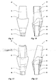
- FIGS. 9 and 10 show two views of another embodiment of a structure, wherein the coronal, the base 10 in the assembled state superior area has a more complex, adapted to a specific tooth geometry structure.
- FIGS. 11 and 12 show a further embodiment of an advantageous construction 40, the embodiment of the FIGS. 9 and 10 is similar, but in the case of an angle between the tooth crown and the artificial root that forms the implant base, is provided.
- FIG. 13 shows an integral embodiment of an implant in which the base 10 and the structure 40 are designed as a common component.
- FIG. 14 schematically shows the structure of a natural row of teeth with roots 60 and crowns 62, wherein the bone boundary 64 and the gingival boundary 66 are shown. Note the interdental papillae 68 projecting high into the interdental space in healthy teeth.
- FIG. 15 schematically shows a row of teeth with an implant according to the prior art. One recognizes the frequent problem that in the spaces between the adjacent teeth of the implant, the interdental papillae 68 are degenerated due to the onset of difficulty.
- FIG. 16 schematically shows a row of teeth with an implant according to the invention. Note that due to the improved accretion, the interdental papillae 68 are formed as with natural teeth.
Landscapes
- Health & Medical Sciences (AREA)
- Oral & Maxillofacial Surgery (AREA)
- Orthopedic Medicine & Surgery (AREA)
- Dentistry (AREA)
- Epidemiology (AREA)
- Life Sciences & Earth Sciences (AREA)
- Animal Behavior & Ethology (AREA)
- General Health & Medical Sciences (AREA)
- Public Health (AREA)
- Veterinary Medicine (AREA)
- Dental Prosthetics (AREA)
Claims (14)
- Implant dentaire, comprenant une base (10) pouvant être partiellement insérée dans un os maxillaire et dotée d'un corps (12) en position apicale et d'un collet (14) en position coronale, dont les surfaces extérieures présentent respectivement une microstructure superficielle de rugosité prédéfinie, sachant que la valeur de la rugosité moyenne de la surface du corps est supérieure à la valeur de la rugosité moyenne de la surface du collet, et que la valeur de la rugosité moyenne de la surface du collet est Ra = 0,55 à 0,71 micromètre,
caractérisé en ce que la valeur de la rugosité moyenne de la surface du corps est Ra = 0,75 à 0,95 micromètre. - Implant dentaire selon la revendication 1, caractérisé en ce que la microstructure superficielle de la surface du corps est produite par une opération de grenaillage avec un agent de grenaillage dur, suivie d'une opération de décapage, et que la microstructure superficielle de la surface du collet est produite par une opération de décapage.
- Implant dentaire selon la revendication 2, caractérisé en ce que l'opération de décapage comprend un décapage avec un agent de décapage basique.
- Implant dentaire selon la revendication 3, caractérisé en ce que l'agent de décapage contient une forte concentration d'hydroxyde de potassium.
- Implant dentaire selon l'une quelconque des revendications précédentes, caractérisé en ce que la base (10) est constituée pour l'essentiel de métal ou d'un alliage métallique, en particulier de titane ou d'un alliage de titane.
- Implant dentaire selon l'une quelconque des revendications précédentes, caractérisé en ce que le corps (12) porte une structure de filetage externe macroscopique.
- Implant dentaire selon l'une quelconque des revendications précédentes, caractérisé en ce que le collet (14) présente une rainure annulaire circonférentielle (22).
- Implant dentaire selon la revendication 7, caractérisé en ce que la rainure annulaire (22) possède une section en forme de segment de cercle avec un rayon de 0,2 à 0,3 millimètre, en particulier d'environ 2,5 millimètres.
- Implant dentaire selon l'une quelconque des revendications précédentes, caractérisé en ce qu'il comprend en outre un pilier (40) qui peut être inséré par une région d'assemblage conique (46) dans une région réceptrice (32) de la base (10) réalisée intérieurement creuse, sachant que la région d'assemblage conique (46) présente une surface extérieure se terminant coniquement en direction apicale sous un angle de cône de pilier, que la région réceptrice (32) présente une surface intérieure (34) se terminant coniquement en direction apicale sous un angle d'ouverture de base, et que l'angle de cône de pilier est plus grand que l'angle d'ouverture de base de 20 à 60 minutes d'arc.
- Implant dentaire selon la revendication 9, caractérisé en ce que le pilier (40) est constitué pour l'essentiel de titane, d'un alliage de titane ou d'oxyde de zirconium.
- Implant dentaire selon la revendication 9 ou 10, caractérisé en ce que le pilier (40) présente, en position apicale par rapport à la région d'assemblage conique (46), une saillie de blocage de rotation (48) qui n'est pas à symétrie de révolution et qui peut être introduite en engagement positif dans un évidement (36) de blocage de rotation correspondant de la base (10).
- Implant dentaire selon l'une quelconque des revendications 1 à 8, caractérisé en ce qu'il comprend en outre un pilier (40) qui se raccorde en position coronale au collet (14) et qui est assemblé à la base d'un seul tenant ou par liaison de matière.
- Procédé de fabrication d'une base (10) d'implant dentaire dotée d'un corps (12) en position apicale et d'un collet (14) en position coronale, comprenant les étapes suivantes :- mise à disposition d'une ébauche de base dotée de surfaces extérieures meulées ou polies,- grenaillage de la surface extérieure du corps (12) avec un agent de grenaillage dur, tout en protégeant de l'agent de grenaillage la surface extérieure du collet,- décapage des surfaces extérieures de la totalité de l'ébauche de base,de telle sorte que la valeur de la rugosité moyenne de la surface du corps est Ra = 0,75 à 0,95 micromètre et que la valeur de la rugosité moyenne de la surface du collet est Ra = 0,55 à 0,71 micromètre.
- Procédé selon la revendication 13, caractérisé en ce que l'étape de décapage comprend un décapage avec un agent de décapage basique, en particulier avec une forte concentration d'hydroxyde de potassium.
Priority Applications (1)
| Application Number | Priority Date | Filing Date | Title |
|---|---|---|---|
| EP12006110A EP2561827A3 (fr) | 2008-02-29 | 2009-02-02 | Implant dentaire et méthode de fabrication dudit imlpant |
Applications Claiming Priority (2)
| Application Number | Priority Date | Filing Date | Title |
|---|---|---|---|
| DE102008011963A DE102008011963A1 (de) | 2008-02-29 | 2008-02-29 | Zahnimplantat und Verfahren zu seiner Herstellung |
| PCT/EP2009/000663 WO2009106205A1 (fr) | 2008-02-29 | 2009-02-02 | Implant dentaire et son procédé de fabrication |
Related Child Applications (1)
| Application Number | Title | Priority Date | Filing Date |
|---|---|---|---|
| EP12006110.6 Division-Into | 2012-08-28 |
Publications (2)
| Publication Number | Publication Date |
|---|---|
| EP2249740A1 EP2249740A1 (fr) | 2010-11-17 |
| EP2249740B1 true EP2249740B1 (fr) | 2012-11-21 |
Family
ID=40637252
Family Applications (2)
| Application Number | Title | Priority Date | Filing Date |
|---|---|---|---|
| EP12006110A Withdrawn EP2561827A3 (fr) | 2008-02-29 | 2009-02-02 | Implant dentaire et méthode de fabrication dudit imlpant |
| EP09714335A Not-in-force EP2249740B1 (fr) | 2008-02-29 | 2009-02-02 | Implant dentaire et son procédé de fabrication |
Family Applications Before (1)
| Application Number | Title | Priority Date | Filing Date |
|---|---|---|---|
| EP12006110A Withdrawn EP2561827A3 (fr) | 2008-02-29 | 2009-02-02 | Implant dentaire et méthode de fabrication dudit imlpant |
Country Status (8)
| Country | Link |
|---|---|
| US (1) | US20110008753A1 (fr) |
| EP (2) | EP2561827A3 (fr) |
| JP (1) | JP5197769B2 (fr) |
| CA (1) | CA2717273C (fr) |
| DE (1) | DE102008011963A1 (fr) |
| ES (1) | ES2399605T3 (fr) |
| PT (1) | PT2249740E (fr) |
| WO (1) | WO2009106205A1 (fr) |
Families Citing this family (23)
| Publication number | Priority date | Publication date | Assignee | Title |
|---|---|---|---|---|
| WO2009142429A2 (fr) * | 2008-05-19 | 2009-11-26 | 오스템임플란트(주) | Fixation pour implant dentaire |
| DE102009050049B4 (de) * | 2009-10-21 | 2012-06-21 | Sören-Michael Usslepp | Einteilige und zweiteilige Zahnersatz-Implantate, mit wellenförmigem Außengewinde und für zweiteilige Implantate, ein auf zwei Positionsvorgaben limitiertes Ankopplungsdesign, für prothetische Bau- und Hilfsteile inkl. derer Tiefen- bzw. Höhenmarkierung |
| GB2475679A (en) * | 2009-11-25 | 2011-06-01 | Andrew Dawood | Bone implant screw |
| US8641418B2 (en) | 2010-03-29 | 2014-02-04 | Biomet 3I, Llc | Titanium nano-scale etching on an implant surface |
| FR2962644B1 (fr) * | 2010-07-19 | 2013-06-28 | Assist Publ Hopitaux De Paris | Implant dentaire comportant un moyen d'etancheite |
| ES2363021B1 (es) * | 2010-12-27 | 2012-02-24 | Terrats Mecanizados, S.L. | Aditamiento protésico mejorado. |
| AT511387B1 (de) | 2011-04-20 | 2013-02-15 | Redtenbacher Praez Steile Ges M B H | Zahnprothese |
| DE102011050335A1 (de) | 2011-05-13 | 2012-11-15 | Microceram Gmbh | Verfahren zur Behandlung von keramischen Oberflächen sowie keramische Implantate auf der Basis von Zirkonoxid |
| EP2586398A1 (fr) * | 2011-10-25 | 2013-05-01 | Sudimplant | Implant dentaire |
| DE102012002614A1 (de) * | 2012-01-24 | 2013-07-25 | 32schönezähne GmbH & Co. KG | Abutment für ein Dentalimplantat-System |
| ES2671740T3 (es) | 2012-03-20 | 2018-06-08 | Biomet 3I, Llc | Superficie de tratamiento para una superficie de implante |
| WO2013180237A1 (fr) * | 2012-05-30 | 2013-12-05 | 京セラメディカル株式会社 | Implant dentaire |
| US10325273B2 (en) * | 2012-09-13 | 2019-06-18 | Facebook, Inc. | User selected affiliation with brands in a social networking system |
| USD765856S1 (en) | 2014-02-14 | 2016-09-06 | Vita Zahnfabrik H. Rauter Gmbh & Co. Kg | Dental implant |
| US12161527B2 (en) | 2014-03-07 | 2024-12-10 | Quadric Biomed, Llc | Dental implant with improved trans-gingival emergence profile |
| FR3036162B1 (fr) | 2015-05-13 | 2017-06-16 | Valeo Vision | Module d'eclairage bifonction code - route pour vehicule automobile |
| EP3334369B1 (fr) | 2015-08-11 | 2020-12-23 | Biomet 3I, LLC | Implant dentaire ayant une surface conique filetée avec des éléments améliorant l'installation |
| BR102016012923A2 (pt) * | 2016-06-06 | 2017-12-19 | Navarro Da Rocha Daniel | processo de alteração nano morfológica superficial em implantes de titânio anodizado |
| IT201600097674A1 (it) * | 2016-09-29 | 2018-03-29 | Maurizio Serafini | impianto dentale per il sollevamento della membrana sinusale per via crestale |
| DE102016014348B4 (de) * | 2016-10-07 | 2019-05-16 | Metin Gürlük | Implantatsystem |
| CN106725939A (zh) * | 2017-01-19 | 2017-05-31 | 常州百康特医疗器械有限公司 | 牙种植体及具有其的牙种植体系统 |
| KR102096885B1 (ko) * | 2017-12-04 | 2020-04-03 | 주식회사 메가젠임플란트 | 치과용 임플란트의 픽스츄어 |
| DE102020113824A1 (de) | 2020-05-22 | 2021-11-25 | medentis medical GmbH | Implantat, Aufbau und Implantatsystem |
Family Cites Families (25)
| Publication number | Priority date | Publication date | Assignee | Title |
|---|---|---|---|---|
| JPS60220056A (ja) * | 1984-04-18 | 1985-11-02 | 三菱マテリアル株式会社 | 人工歯 |
| US4872840A (en) * | 1987-07-15 | 1989-10-10 | Team Incorporated | Dental implant and method |
| JPH06125978A (ja) * | 1991-11-25 | 1994-05-10 | Nikon Corp | インプラント体の製造方法 |
| DE4407993C2 (de) * | 1994-03-10 | 1999-05-06 | Friatec Ag | Dentalimplantat |
| JPH07328038A (ja) * | 1994-06-15 | 1995-12-19 | Nikon Corp | 骨内インプラント |
| JPH07328036A (ja) * | 1994-06-15 | 1995-12-19 | Nikon Corp | 骨内インプラントおよびその製造方法 |
| EP0707835B1 (fr) * | 1994-10-17 | 2000-03-08 | Degussa-Hüls Aktiengesellschaft | Implant dentaire diphasé |
| BR9509934A (pt) | 1994-11-30 | 1998-01-27 | Implant Innovations Inc | Preparação de superficie de implante |
| DE69535892D1 (de) * | 1995-12-08 | 2009-01-08 | Zimmer Dental Inc | Zahnimplantat mit mehrfach strukturierter oberfläche |
| DE19828018A1 (de) * | 1998-06-24 | 1999-12-30 | Wieland Edelmetalle | Implantat sowie Implantataufbauteile für ein Implantatsystem |
| ES2158777B1 (es) * | 1998-07-08 | 2002-03-01 | Alvaro Manuel Perona | Pieza para implantes dentales. |
| IT1307923B1 (it) | 1999-01-25 | 2001-11-29 | Hofmann S A S Di Roberto Hofma | Dispositivo di impianto dentale endosseo. |
| AU2001221607A1 (en) * | 2000-11-20 | 2002-05-27 | Ecole Polytechnique Federale De Lausanne (Epfl) | Endosseous implant |
| DE10138374A1 (de) * | 2001-08-11 | 2003-03-06 | Robert Eisenburger | Dentalimplantat und Verschlußkappe |
| DE10159683A1 (de) * | 2001-11-30 | 2003-06-18 | Michael Gahlert | Dantalimplantat |
| BR0215756A (pt) * | 2002-06-06 | 2005-03-01 | Nobel Biocare Ab | Implantes dentários e métodos de instalação de prótese dentária, de aumento da ligação do tecido entre uma prótese dentária e o tecido de aderência do paciente e de fabrico de implante dentário |
| ITMI20021377A1 (it) | 2002-06-21 | 2003-12-22 | Milano Politecnico | Interfaccia ostointegrativa per protesi impiantabili e metodo per il trattamento di detta interfaccia ostointegrativa |
| ATE345747T1 (de) * | 2003-01-23 | 2006-12-15 | Dinkelacker Wolfgang | Knochenimplantat und verfahren zu seiner herstellung |
| US8251700B2 (en) | 2003-05-16 | 2012-08-28 | Biomet 3I, Llc | Surface treatment process for implants made of titanium alloy |
| EP1529497B1 (fr) * | 2003-11-04 | 2009-10-28 | Friadent GmbH | Composant Implant Dentaire |
| PT1529498E (pt) * | 2003-11-05 | 2014-09-17 | Dentsply Implants Mfg Gmbh | Implante não metálico de várias peças |
| US7249949B2 (en) * | 2004-06-29 | 2007-07-31 | Lifecore Biomedical, Inc. | Internal connection dental implant |
| DE102005005746B4 (de) * | 2005-02-07 | 2014-05-15 | Stefan Neumeyer | Zahnimplantat |
| DE202005005421U1 (de) * | 2005-04-05 | 2006-08-10 | Dinkelacker, Wolfgang, Dr.med.dent. | Schraubenförmiges Dentalimplantat |
| EP1931277B1 (fr) * | 2005-09-02 | 2011-11-16 | DENTSPLY Friadent GmbH | Implant dentaire à mise en charge immédiate |
-
2008
- 2008-02-29 DE DE102008011963A patent/DE102008011963A1/de not_active Withdrawn
-
2009
- 2009-02-02 EP EP12006110A patent/EP2561827A3/fr not_active Withdrawn
- 2009-02-02 CA CA2717273A patent/CA2717273C/fr not_active Expired - Fee Related
- 2009-02-02 EP EP09714335A patent/EP2249740B1/fr not_active Not-in-force
- 2009-02-02 WO PCT/EP2009/000663 patent/WO2009106205A1/fr not_active Ceased
- 2009-02-02 PT PT97143358T patent/PT2249740E/pt unknown
- 2009-02-02 US US12/919,766 patent/US20110008753A1/en not_active Abandoned
- 2009-02-02 JP JP2010547980A patent/JP5197769B2/ja not_active Expired - Fee Related
- 2009-02-02 ES ES09714335T patent/ES2399605T3/es active Active
Also Published As
| Publication number | Publication date |
|---|---|
| JP2011512913A (ja) | 2011-04-28 |
| CA2717273A1 (fr) | 2009-09-03 |
| EP2249740A1 (fr) | 2010-11-17 |
| ES2399605T3 (es) | 2013-04-02 |
| DE102008011963A1 (de) | 2009-09-10 |
| EP2561827A2 (fr) | 2013-02-27 |
| PT2249740E (pt) | 2013-02-21 |
| CA2717273C (fr) | 2014-01-21 |
| WO2009106205A1 (fr) | 2009-09-03 |
| EP2561827A3 (fr) | 2013-03-20 |
| JP5197769B2 (ja) | 2013-05-15 |
| US20110008753A1 (en) | 2011-01-13 |
Similar Documents
| Publication | Publication Date | Title |
|---|---|---|
| EP2249740B1 (fr) | Implant dentaire et son procédé de fabrication | |
| EP1450722B2 (fr) | Implant dentaire c ramique | |
| DE10019338B4 (de) | Implantat | |
| EP2667820B1 (fr) | Système de prothèse dentaire | |
| EP3082640B1 (fr) | Implant dentaire individuel placé à l'intérieur d'un os | |
| EP2170212B1 (fr) | Implant dentaire | |
| EP1617783B1 (fr) | Implant dentaire | |
| DE102005013200B4 (de) | Zweiteiliges Zahnimplantat aus Keramik | |
| EP2170213B1 (fr) | Implant dentaire | |
| EP0438048A1 (fr) | Implant dentaire | |
| EP2654603A1 (fr) | Implant crestal et procédé pour son traitement | |
| EP3685795B1 (fr) | Implant unitaire endo-osseux | |
| DE4326841A1 (de) | Implantat-Bausatz | |
| EP1462066B1 (fr) | Implant dentaire comportant un faux-moignon incliné | |
| DE102007046879A1 (de) | Dentalimplantat | |
| EP1006926A2 (fr) | Systeme d'implant, ainsi que procede et outils pour la pose d'un implant dans une machoire sans dents | |
| DE102004052024A1 (de) | Zahnimplantat | |
| WO2012126716A1 (fr) | Implant dentaire et procédé de fabrication ou de traitement d'un implant dentaire | |
| EP3666224A1 (fr) | Prothèse dentaire pourvue de manchon de raccordement | |
| EP2724686A2 (fr) | Implant dentaire et système d'implant dentaire | |
| EP2331008B1 (fr) | Système d'implant pour la fixation de dents artificielles | |
| CH703012A1 (de) | Dentalimplantat. | |
| DE19632916A1 (de) | Implantatsystem zur Verankerung von Zahnersatz im Kiefer | |
| DE102016014348B4 (de) | Implantatsystem | |
| EP3192470B1 (fr) | Implant dentaire comprenant un filetage a filets multiples |
Legal Events
| Date | Code | Title | Description |
|---|---|---|---|
| PUAI | Public reference made under article 153(3) epc to a published international application that has entered the european phase |
Free format text: ORIGINAL CODE: 0009012 |
|
| 17P | Request for examination filed |
Effective date: 20100924 |
|
| AK | Designated contracting states |
Kind code of ref document: A1 Designated state(s): AT BE BG CH CY CZ DE DK EE ES FI FR GB GR HR HU IE IS IT LI LT LU LV MC MK MT NL NO PL PT RO SE SI SK TR |
|
| AX | Request for extension of the european patent |
Extension state: AL BA RS |
|
| DAX | Request for extension of the european patent (deleted) | ||
| GRAP | Despatch of communication of intention to grant a patent |
Free format text: ORIGINAL CODE: EPIDOSNIGR1 |
|
| GRAS | Grant fee paid |
Free format text: ORIGINAL CODE: EPIDOSNIGR3 |
|
| GRAA | (expected) grant |
Free format text: ORIGINAL CODE: 0009210 |
|
| AK | Designated contracting states |
Kind code of ref document: B1 Designated state(s): AT BE BG CH CY CZ DE DK EE ES FI FR GB GR HR HU IE IS IT LI LT LU LV MC MK MT NL NO PL PT RO SE SI SK TR |
|
| REG | Reference to a national code |
Ref country code: GB Ref legal event code: FG4D Free format text: NOT ENGLISH |
|
| REG | Reference to a national code |
Ref country code: CH Ref legal event code: EP |
|
| REG | Reference to a national code |
Ref country code: AT Ref legal event code: REF Ref document number: 584646 Country of ref document: AT Kind code of ref document: T Effective date: 20121215 |
|
| REG | Reference to a national code |
Ref country code: IE Ref legal event code: FG4D Free format text: LANGUAGE OF EP DOCUMENT: GERMAN |
|
| REG | Reference to a national code |
Ref country code: DE Ref legal event code: R096 Ref document number: 502009005444 Country of ref document: DE Effective date: 20130117 |
|
| REG | Reference to a national code |
Ref country code: PT Ref legal event code: SC4A Free format text: AVAILABILITY OF NATIONAL TRANSLATION Effective date: 20130211 |
|
| REG | Reference to a national code |
Ref country code: ES Ref legal event code: FG2A Ref document number: 2399605 Country of ref document: ES Kind code of ref document: T3 Effective date: 20130402 |
|
| REG | Reference to a national code |
Ref country code: NL Ref legal event code: VDEP Effective date: 20121121 |
|
| REG | Reference to a national code |
Ref country code: LT Ref legal event code: MG4D |
|
| PG25 | Lapsed in a contracting state [announced via postgrant information from national office to epo] |
Ref country code: LT Free format text: LAPSE BECAUSE OF FAILURE TO SUBMIT A TRANSLATION OF THE DESCRIPTION OR TO PAY THE FEE WITHIN THE PRESCRIBED TIME-LIMIT Effective date: 20121121 Ref country code: FI Free format text: LAPSE BECAUSE OF FAILURE TO SUBMIT A TRANSLATION OF THE DESCRIPTION OR TO PAY THE FEE WITHIN THE PRESCRIBED TIME-LIMIT Effective date: 20121121 Ref country code: SE Free format text: LAPSE BECAUSE OF FAILURE TO SUBMIT A TRANSLATION OF THE DESCRIPTION OR TO PAY THE FEE WITHIN THE PRESCRIBED TIME-LIMIT Effective date: 20121121 Ref country code: NO Free format text: LAPSE BECAUSE OF FAILURE TO SUBMIT A TRANSLATION OF THE DESCRIPTION OR TO PAY THE FEE WITHIN THE PRESCRIBED TIME-LIMIT Effective date: 20130221 |
|
| PG25 | Lapsed in a contracting state [announced via postgrant information from national office to epo] |
Ref country code: PL Free format text: LAPSE BECAUSE OF FAILURE TO SUBMIT A TRANSLATION OF THE DESCRIPTION OR TO PAY THE FEE WITHIN THE PRESCRIBED TIME-LIMIT Effective date: 20121121 Ref country code: SI Free format text: LAPSE BECAUSE OF FAILURE TO SUBMIT A TRANSLATION OF THE DESCRIPTION OR TO PAY THE FEE WITHIN THE PRESCRIBED TIME-LIMIT Effective date: 20121121 Ref country code: LV Free format text: LAPSE BECAUSE OF FAILURE TO SUBMIT A TRANSLATION OF THE DESCRIPTION OR TO PAY THE FEE WITHIN THE PRESCRIBED TIME-LIMIT Effective date: 20121121 Ref country code: GR Free format text: LAPSE BECAUSE OF FAILURE TO SUBMIT A TRANSLATION OF THE DESCRIPTION OR TO PAY THE FEE WITHIN THE PRESCRIBED TIME-LIMIT Effective date: 20130222 |
|
| PG25 | Lapsed in a contracting state [announced via postgrant information from national office to epo] |
Ref country code: CZ Free format text: LAPSE BECAUSE OF FAILURE TO SUBMIT A TRANSLATION OF THE DESCRIPTION OR TO PAY THE FEE WITHIN THE PRESCRIBED TIME-LIMIT Effective date: 20121121 Ref country code: DK Free format text: LAPSE BECAUSE OF FAILURE TO SUBMIT A TRANSLATION OF THE DESCRIPTION OR TO PAY THE FEE WITHIN THE PRESCRIBED TIME-LIMIT Effective date: 20121121 Ref country code: BG Free format text: LAPSE BECAUSE OF FAILURE TO SUBMIT A TRANSLATION OF THE DESCRIPTION OR TO PAY THE FEE WITHIN THE PRESCRIBED TIME-LIMIT Effective date: 20130221 Ref country code: SK Free format text: LAPSE BECAUSE OF FAILURE TO SUBMIT A TRANSLATION OF THE DESCRIPTION OR TO PAY THE FEE WITHIN THE PRESCRIBED TIME-LIMIT Effective date: 20121121 Ref country code: EE Free format text: LAPSE BECAUSE OF FAILURE TO SUBMIT A TRANSLATION OF THE DESCRIPTION OR TO PAY THE FEE WITHIN THE PRESCRIBED TIME-LIMIT Effective date: 20121121 |
|
| PG25 | Lapsed in a contracting state [announced via postgrant information from national office to epo] |
Ref country code: RO Free format text: LAPSE BECAUSE OF FAILURE TO SUBMIT A TRANSLATION OF THE DESCRIPTION OR TO PAY THE FEE WITHIN THE PRESCRIBED TIME-LIMIT Effective date: 20121121 Ref country code: NL Free format text: LAPSE BECAUSE OF FAILURE TO SUBMIT A TRANSLATION OF THE DESCRIPTION OR TO PAY THE FEE WITHIN THE PRESCRIBED TIME-LIMIT Effective date: 20121121 |
|
| BERE | Be: lapsed |
Owner name: RUPPRECHT, BERND Effective date: 20130228 Owner name: CYRON, AXEL Effective date: 20130228 |
|
| PLBE | No opposition filed within time limit |
Free format text: ORIGINAL CODE: 0009261 |
|
| STAA | Information on the status of an ep patent application or granted ep patent |
Free format text: STATUS: NO OPPOSITION FILED WITHIN TIME LIMIT |
|
| PG25 | Lapsed in a contracting state [announced via postgrant information from national office to epo] |
Ref country code: MC Free format text: LAPSE BECAUSE OF NON-PAYMENT OF DUE FEES Effective date: 20130228 |
|
| GBPC | Gb: european patent ceased through non-payment of renewal fee |
Effective date: 20130221 |
|
| 26N | No opposition filed |
Effective date: 20130822 |
|
| PG25 | Lapsed in a contracting state [announced via postgrant information from national office to epo] |
Ref country code: HR Free format text: LAPSE BECAUSE OF FAILURE TO SUBMIT A TRANSLATION OF THE DESCRIPTION OR TO PAY THE FEE WITHIN THE PRESCRIBED TIME-LIMIT Effective date: 20121121 |
|
| REG | Reference to a national code |
Ref country code: IE Ref legal event code: MM4A |
|
| REG | Reference to a national code |
Ref country code: DE Ref legal event code: R097 Ref document number: 502009005444 Country of ref document: DE Effective date: 20130822 |
|
| PG25 | Lapsed in a contracting state [announced via postgrant information from national office to epo] |
Ref country code: GB Free format text: LAPSE BECAUSE OF NON-PAYMENT OF DUE FEES Effective date: 20130221 Ref country code: BE Free format text: LAPSE BECAUSE OF NON-PAYMENT OF DUE FEES Effective date: 20130228 Ref country code: IE Free format text: LAPSE BECAUSE OF NON-PAYMENT OF DUE FEES Effective date: 20130202 |
|
| PG25 | Lapsed in a contracting state [announced via postgrant information from national office to epo] |
Ref country code: MT Free format text: LAPSE BECAUSE OF FAILURE TO SUBMIT A TRANSLATION OF THE DESCRIPTION OR TO PAY THE FEE WITHIN THE PRESCRIBED TIME-LIMIT Effective date: 20121121 |
|
| PG25 | Lapsed in a contracting state [announced via postgrant information from national office to epo] |
Ref country code: TR Free format text: LAPSE BECAUSE OF FAILURE TO SUBMIT A TRANSLATION OF THE DESCRIPTION OR TO PAY THE FEE WITHIN THE PRESCRIBED TIME-LIMIT Effective date: 20121121 Ref country code: CY Free format text: LAPSE BECAUSE OF FAILURE TO SUBMIT A TRANSLATION OF THE DESCRIPTION OR TO PAY THE FEE WITHIN THE PRESCRIBED TIME-LIMIT Effective date: 20121121 |
|
| PG25 | Lapsed in a contracting state [announced via postgrant information from national office to epo] |
Ref country code: HU Free format text: LAPSE BECAUSE OF FAILURE TO SUBMIT A TRANSLATION OF THE DESCRIPTION OR TO PAY THE FEE WITHIN THE PRESCRIBED TIME-LIMIT; INVALID AB INITIO Effective date: 20090202 Ref country code: MK Free format text: LAPSE BECAUSE OF FAILURE TO SUBMIT A TRANSLATION OF THE DESCRIPTION OR TO PAY THE FEE WITHIN THE PRESCRIBED TIME-LIMIT Effective date: 20121121 Ref country code: LU Free format text: LAPSE BECAUSE OF NON-PAYMENT OF DUE FEES Effective date: 20130202 |
|
| REG | Reference to a national code |
Ref country code: FR Ref legal event code: PLFP Year of fee payment: 8 |
|
| PG25 | Lapsed in a contracting state [announced via postgrant information from national office to epo] |
Ref country code: IS Free format text: LAPSE BECAUSE OF FAILURE TO SUBMIT A TRANSLATION OF THE DESCRIPTION OR TO PAY THE FEE WITHIN THE PRESCRIBED TIME-LIMIT Effective date: 20121121 |
|
| REG | Reference to a national code |
Ref country code: FR Ref legal event code: PLFP Year of fee payment: 9 |
|
| REG | Reference to a national code |
Ref country code: FR Ref legal event code: PLFP Year of fee payment: 10 |
|
| REG | Reference to a national code |
Ref country code: CH Ref legal event code: PUEA Owner name: RUPPRECHT, BERND, DE Free format text: FORMER OWNER: RUPPRECHT, BERND, DE |
|
| REG | Reference to a national code |
Ref country code: DE Ref legal event code: R082 Ref document number: 502009005444 Country of ref document: DE Representative=s name: ACTIVELAW KLEIN.OFFENHAUSEN.WOLF. RECHTS- U. F, DE Ref country code: DE Ref legal event code: R081 Ref document number: 502009005444 Country of ref document: DE Owner name: RUPPRECHT, BERND, DR. MED., DE Free format text: FORMER OWNERS: CYRON, AXEL, 38229 SALZGITTER, DE; RUPPRECHT, BERND, DR. MED., 37327 LEINEFELDE, DE Ref country code: DE Ref legal event code: R082 Ref document number: 502009005444 Country of ref document: DE Representative=s name: FIEDLER, OSTERMANN & SCHNEIDER - PATENTANWAELT, DE |
|
| REG | Reference to a national code |
Ref country code: AT Ref legal event code: PC Ref document number: 584646 Country of ref document: AT Kind code of ref document: T Owner name: RUPPRECHT, BERND, DE Effective date: 20191115 |
|
| REG | Reference to a national code |
Ref country code: DE Ref legal event code: R082 Ref document number: 502009005444 Country of ref document: DE Representative=s name: FIEDLER, OSTERMANN & SCHNEIDER - PATENTANWAELT, DE |
|
| REG | Reference to a national code |
Ref country code: CH Ref legal event code: PCAR Free format text: NEW ADDRESS: ROTENBODENSTRASSE 12, 9497 TRIESENBERG (LI) |
|
| PGFP | Annual fee paid to national office [announced via postgrant information from national office to epo] |
Ref country code: PT Payment date: 20210222 Year of fee payment: 13 Ref country code: CH Payment date: 20210222 Year of fee payment: 13 Ref country code: IT Payment date: 20210226 Year of fee payment: 13 Ref country code: FR Payment date: 20210217 Year of fee payment: 13 |
|
| PGFP | Annual fee paid to national office [announced via postgrant information from national office to epo] |
Ref country code: AT Payment date: 20210216 Year of fee payment: 13 Ref country code: ES Payment date: 20210323 Year of fee payment: 13 Ref country code: DE Payment date: 20210212 Year of fee payment: 13 |
|
| REG | Reference to a national code |
Ref country code: DE Ref legal event code: R119 Ref document number: 502009005444 Country of ref document: DE |
|
| REG | Reference to a national code |
Ref country code: CH Ref legal event code: PL |
|
| REG | Reference to a national code |
Ref country code: AT Ref legal event code: MM01 Ref document number: 584646 Country of ref document: AT Kind code of ref document: T Effective date: 20220202 |
|
| PG25 | Lapsed in a contracting state [announced via postgrant information from national office to epo] |
Ref country code: PT Free format text: LAPSE BECAUSE OF NON-PAYMENT OF DUE FEES Effective date: 20220802 Ref country code: AT Free format text: LAPSE BECAUSE OF NON-PAYMENT OF DUE FEES Effective date: 20220202 |
|
| PG25 | Lapsed in a contracting state [announced via postgrant information from national office to epo] |
Ref country code: FR Free format text: LAPSE BECAUSE OF NON-PAYMENT OF DUE FEES Effective date: 20220228 |
|
| PG25 | Lapsed in a contracting state [announced via postgrant information from national office to epo] |
Ref country code: LI Free format text: LAPSE BECAUSE OF NON-PAYMENT OF DUE FEES Effective date: 20220228 Ref country code: DE Free format text: LAPSE BECAUSE OF NON-PAYMENT OF DUE FEES Effective date: 20220901 Ref country code: CH Free format text: LAPSE BECAUSE OF NON-PAYMENT OF DUE FEES Effective date: 20220228 |
|
| REG | Reference to a national code |
Ref country code: ES Ref legal event code: FD2A Effective date: 20230330 |
|
| PG25 | Lapsed in a contracting state [announced via postgrant information from national office to epo] |
Ref country code: ES Free format text: LAPSE BECAUSE OF NON-PAYMENT OF DUE FEES Effective date: 20220203 |
|
| PG25 | Lapsed in a contracting state [announced via postgrant information from national office to epo] |
Ref country code: IT Free format text: LAPSE BECAUSE OF NON-PAYMENT OF DUE FEES Effective date: 20220202 |