EP2250965A1 - Procédé d'acquisition d'images, dispositif et système de radiographie - Google Patents
Procédé d'acquisition d'images, dispositif et système de radiographie Download PDFInfo
- Publication number
- EP2250965A1 EP2250965A1 EP10161544A EP10161544A EP2250965A1 EP 2250965 A1 EP2250965 A1 EP 2250965A1 EP 10161544 A EP10161544 A EP 10161544A EP 10161544 A EP10161544 A EP 10161544A EP 2250965 A1 EP2250965 A1 EP 2250965A1
- Authority
- EP
- European Patent Office
- Prior art keywords
- interest
- region
- sub
- images
- detector
- Prior art date
- Legal status (The legal status is an assumption and is not a legal conclusion. Google has not performed a legal analysis and makes no representation as to the accuracy of the status listed.)
- Granted
Links
Images





Classifications
-
- A—HUMAN NECESSITIES
- A61—MEDICAL OR VETERINARY SCIENCE; HYGIENE
- A61B—DIAGNOSIS; SURGERY; IDENTIFICATION
- A61B6/00—Apparatus or devices for radiation diagnosis; Apparatus or devices for radiation diagnosis combined with radiation therapy equipment
- A61B6/46—Arrangements for interfacing with the operator or the patient
- A61B6/467—Arrangements for interfacing with the operator or the patient characterised by special input means
- A61B6/469—Arrangements for interfacing with the operator or the patient characterised by special input means for selecting a region of interest [ROI]
-
- A—HUMAN NECESSITIES
- A61—MEDICAL OR VETERINARY SCIENCE; HYGIENE
- A61B—DIAGNOSIS; SURGERY; IDENTIFICATION
- A61B6/00—Apparatus or devices for radiation diagnosis; Apparatus or devices for radiation diagnosis combined with radiation therapy equipment
- A61B6/44—Constructional features of apparatus for radiation diagnosis
- A61B6/4429—Constructional features of apparatus for radiation diagnosis related to the mounting of source units and detector units
- A61B6/4435—Constructional features of apparatus for radiation diagnosis related to the mounting of source units and detector units the source unit and the detector unit being coupled by a rigid structure
- A61B6/4441—Constructional features of apparatus for radiation diagnosis related to the mounting of source units and detector units the source unit and the detector unit being coupled by a rigid structure the rigid structure being a C-arm or U-arm
-
- A—HUMAN NECESSITIES
- A61—MEDICAL OR VETERINARY SCIENCE; HYGIENE
- A61B—DIAGNOSIS; SURGERY; IDENTIFICATION
- A61B6/00—Apparatus or devices for radiation diagnosis; Apparatus or devices for radiation diagnosis combined with radiation therapy equipment
- A61B6/52—Devices using data or image processing specially adapted for radiation diagnosis
- A61B6/5211—Devices using data or image processing specially adapted for radiation diagnosis involving processing of medical diagnostic data
- A61B6/5229—Devices using data or image processing specially adapted for radiation diagnosis involving processing of medical diagnostic data combining image data of a patient, e.g. combining a functional image with an anatomical image
- A61B6/5235—Devices using data or image processing specially adapted for radiation diagnosis involving processing of medical diagnostic data combining image data of a patient, e.g. combining a functional image with an anatomical image combining images from the same or different ionising radiation imaging techniques, e.g. PET and CT
- A61B6/5241—Devices using data or image processing specially adapted for radiation diagnosis involving processing of medical diagnostic data combining image data of a patient, e.g. combining a functional image with an anatomical image combining images from the same or different ionising radiation imaging techniques, e.g. PET and CT combining overlapping images of the same imaging modality, e.g. by stitching
Definitions
- the present invention generally relates to the field of medical digital radiography systems and, particularly, to an image acquisition method, device and a radiography system.
- FIG. 1 shows an X-ray machine, and the main parts thereof include an X-ray tube 1, an X-ray collimator 2, a patient securing device 3, a detector 4, wherein the main function of the X-ray tube 1 is to emit X-ray; the main function of the X-ray collimator 2 is to limit the radiation range of light field of X-ray emitted by the X-ray tube 1; the function of the detector 4 lies in receiving X-ray and imaging and then transmitting to a workstation for further processing; the function of the patient securing device 3 lies in two points: the first point is to isolate a patient from the detector 4 for safety, and the second point is to fix a patient so as to minimize the movements of the patient in the whole process of capturing.
- the tube 1 emits X-ray through a region of interest, which then comes to the X-ray detector 4 so that the image of the region of interest is acquired.
- the size of the obtained image is generally equal to the size of the X-ray detector. If the field of view of a region of interest is within the size of the X-ray detector, the entire region of interest can be completely presented in one image. For example, the fields of view of regions of interest such as heart, lung and the like are within the size of X-ray detector, so the regions of interest such as heart, lung and the like can be fully shown in an image.
- one category is angulated acquisition method, including capturing multiple sub-images of a region of interest by angulating a tube, i.e. changing the angles of a tube.
- angulated acquisition method including capturing multiple sub-images of a region of interest by angulating a tube, i.e. changing the angles of a tube.
- capturing a sub-image related to a region of interest when the tube is at a certain angle and then capturing a sub-image related to the region of interest when the tube is changed to another angle, and so on, till the region of interest is completely covered in all sub-images.
- pasting all the sub-images together to form an image of the region of interest for example, the applicant company's patent US7177455 adopts the method of angulating the tubes to acquire a image of a region of interest.
- Said US7177455 mainly has the following defects:
- said US7177455 discloses that the first sub-image and the second sub-image have an overlap.
- a tube moves on a parallel movement plane 14 of the tube and emits X-ray to irradiate patients.
- the detector is disposed on a detector incident plane 12.
- the other category is a method of the parallel movement of a tube and an X-ray detector. That is, capturing a sub-image when the tube and the X-ray detector are at a first position, and then simultaneously moving the tube and the X-ray detector in parallel to a second position, and then capturing a sub-image, and so on and so forth, parallelly moving the tube and the X-ray detector in sequence till the end of the region of interest and finally paste the obtained sub-images together to form an image of said region of interest.
- Such an image mosaic method is to manually move the positions of the tube and the X-ray detector in parallel. That is, after capturing of each sub-image, the operator shall manually move the tube and the X-ray detector in parallel to the next position based on experience. As a result of manual operation, working efficiency is low, and because different operators have different experience, the finally acquired image of a region of interest is often inaccurate.
- US6944265 is similar to US7177455 .
- the disclosed overlap thereof is defined on the sub-image plane, namely the first sub-image and the second sub-image overlapping.
- US6944265 also has the defects of rendering the finally acquired image of a region of interest inaccurate, similar to US7177455 .
- One main problem to be addressed by the present invention is to provide an image acquisition method, device and a radiography system to acquire accurate images.
- the image acquisition method of various aspects of the present invention is used for imaging regions of interest of patients by a radiography system.
- Said radiography system comprises a tube and a detector disposed on opposite positions.
- the image acquisition method comprises: determination step: determining the starting position, the ending position of a region of interest, and the value of overlap of the region of interest in the two adjacent sub-images; calculation step: calculating the number of the sub-images required to be captured, the component of field of view at the direction of tube movement as well as the positions of the tube and the detector corresponding to each sub-image based on the starting position and the ending position of a region of interest and the value of said overlap; capturation step: moving the tube and the detector to each position and capturing the region of interest to obtain several sub-images at said positions; pasting step: pasting the several sub-images together to form an image of the said region of interest.
- said calculation step further comprises: calculating a patient coverage on the plane of a region of interest based on the starting position and the ending position of the region of interest; calculating the number of the sub-images required to be captured based on the patent coverage, the distance from said detector incident plane to the plane of the region of interest, the distance from the focus to said detector incident plane and the value of said overlap; calculating the component of said field of view at the direction of the tube movement based on the number of the sub-images required to be captured, the distance from said detector incident plane to the plane of the region of interest, the distance from the focus to said detector incident plane and the value of said overlap; calculating the positions of the tube and the detector corresponding to each sub-image based on the patient coverage, the component of said field of view at the direction of the tube movement, the distance from said detector incident plane to the plane of the region of interest, and the number of said sub-images.
- said pasting step further comprises: cutting off the useless information in said sub-images; determining the search scope as required in the registering of the adjacent images based on the overlap value of the region of interest in the two adjacent sub-images; determining the relative positions matched between the adjacent images from calculating the similarities between the adjacent images based on said search scope; performing image merging on the corresponding pixels of the adjacent images based on said relative positions; conducting vertical equalization of the merged image.
- the value of said overlap is preferably from 5cm to 7cm.
- the image acquisition device of various aspects of the present invention is used for imaging the regions of interest of patients by a radiography system which comprises a tube and a detector disposed on opposite positions.
- the image acquisition device comprises: determination unit: for determining the starting position and the ending position of a region of interest, and the value of overlap of the region of interest in the two adjacent sub-images; calculation unit: for calculating the number of the sub-images required to be obtained, the component of field of view at the direction of tube movement as well as the positions of the tube and the detector corresponding to each sub-image based on the starting position and the ending position of a region of interest and the value of said overlap; capturation unit: for moving the tube and the detector to each position and controlling the tube to capture the region of interest to obtain several sub-images at said positions; pasting unit: for pasting the several sub-images together to form an image of the said region of interest.
- said calculation unit further comprises: the first unit, or calculating a patient coverage on the plane of a region of interest based on the starting position and the ending position of the region of interest; the second unit, for calculating the number of the sub-images required to be captured based on the patent coverage, the distance from said detector incident plane to the plane of the region of interest, the distance from the focus to said detector incident plane and the value of said overlap; the third unit, for calculating the component of said field of view at the direction of the tube movement based on the number of the sub-images required to be captured, the distance from said detector incident plane to the plane of the region of interest, the distance from the focus to said detector incident plane and the value of said overlap; the fourth unit, for calculating the positions of the tube and the detector corresponding to each sub-image based on the patient coverage, the component of said field of view at the direction of the tube movement, the distance from said detector incident plane to the plane of the region of interest, and the number of said sub-images.
- said pasting unit further comprises: cutting unit, for cutting off the useless information in said sub-images; search scope determining unit, for determining the search scope as required in the registering of the adjacent images based on the overlap value of the region of interest in the two adjacent sub-images; relative position determining unit, used for determining the relative positions matched between the adjacent images from calculating the similarities between the adjacent images based on said search scope; merging unit, for performing image merging on the corresponding pixels of the adjacent images based on said relative positions; vertical equalization unit, for conducting vertical equalization of the merged image.
- the value of said overlap is preferably from 5cm to 7cm.
- Said radiography system comprises of a tube and a detector disposed on opposite positions, and further comprises an image acquisition device.
- Said image acquisition device comprises: determination unit: for determining the starting position and the ending position of a region of interest, and the value of overlap of the region of interest in the two adjacent sub-images; calculation unit: for calculating the number of the sub-images required to be captured, the component of field of view at the direction of tube movement as well as the positions of the tube and the detector corresponding to each sub-image based on the starting position and the ending position of a region of interest and the value of said overlap; capturation unit: for moving the tube and the detector to each position and controlling the tube to capture the region of interest to obtain several sub-images at said positions; pasting unit: for pasting the several sub-images together to form an image of the said region of interest.
- said calculation unit further comprises: the first unit, for calculating a patient coverage on the plane of a region of interest based on the starting position and the ending position of the region of interest; the second unit, for calculating the number of the sub-images required to be captured based on the patent coverage, the distance from said detector incident plane to the plane of the region of interest, the distance from the focus to said detector incident plane and the value of said overlap; the third unit, for calculating the component of said field of view at the direction of the tube movement based on the number of the sub-images required to be captured, the distance from said detector incident plane to the plane of the region of interest, the distance from the focus to said detector incident plane and the value of said overlap; the fourth unit, for calculating the positions of the tube and the detector corresponding to each sub-image based on the patient coverage, the component of said field of view at the direction of the tube movement, the distance from said detector incident plane to the plane of the region of interest, and the number of said sub-images.
- various aspects of the present invention use a mode of determining the starting position and the ending position, and then automatically determining the exposure position, the X-ray field of view, the number of exposures, etc., so these various aspects of the present invention can increase working efficiency and save the operator's time.
- said X-ray machine mainly comprises of the X-ray tube 1, the X-ray collimator 2, the patient securing device 3, and the detector 4.
- the following introduces the technical solution of various aspects of the present invention on the basis of this X-ray machine.
- the image acquisition method of various embodiments of the present invention firstly determines the starting position and the ending position of a region of interest, and the value of overlap of the region of interest in the two adjacent sub-images.
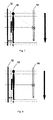
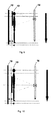
- There can be many modes to determine the starting position and the ending position of a region of interest such as a mode of angulating a tube or a mode of tube parallel moving, as shown in Figure 4A and Figure 4B , which are schematic drawings of exemplary embodiments to determine the starting position and the ending position of a region of interest.
- Figure 4A is the angulation determination mode
- Figure 4B is the parallel movement determination mode.
- the angulation determination mode can determine a staring position 15 and an ending position 16 of the region of interest on the plane 13 of the region of interest by rotating the tube 1; the parallel movement determination mode can determine the staring position 15 and the ending position 16 of the region of interest by parallelly moving the tube. Then the number of sub-images required to be captured, the component of the field of view at the direction of tube movement as well as the positions of the tube 1 and the detector 4 corresponding to each sub-image can be calculated based on the starting position 15 and the ending position 16 of the region of interest and the value of said overlap 17.
- the tube 1 and the detector 4 After determining the positions of the tube 1 and the detector 4 for capturing each sub-image, the tube 1 and the detector 4 will be moved to each of the determined positions to capture the region of interest, namely capturing one sub-image in each position, and the number of captured sub-images is equal to the calculated number of sub-images required to be captured.
- the tube 1 moves along a tube parallel moving plane 14, and the detector 4 moves along a detector incident plane 12, and the corresponding relationship between the exposure positions (positions of tube and detector) and the sub-images required to be captured is indicated; finally these captured sub-images are pasted together to obtain the images of regions of interest.
- the technical solution of the image acquisition method of various aspects of the present invention can guarantee that there is an overlap of a region of interest in the two adjacent sub-images, rather than as described in US patent US7177455 that just guarantees an overlap of the first sub-image and the second sub-image.
- An overlap of the first sub-image and the second sub-image does not guarantee the overlap of the region of interest in the sub-images, so the images acquired by using sub-image acquisition method of the present invention are more accurate.
- the value of said overlap 17 can be 5cm to 7cm, or also can be other values. Such an overlap value discovered through a series of experiments can achieve the best balance of the number of exposures and the image quality.
- said calculation step further comprises: Step 20) calculating a patient coverage on the plane of a region of interest based on the starting position and the ending position of the region of interest; Step 21) calculating the number of the sub-images required to be captured based on the patent coverage, the distance from said detector incident plane to the plane of the region of interest, the distance from the focus to said detector incident plane and the value of said overlap; Step 22) calculating the component of the field of view at the direction of the tube movement based on the number of the sub-images required to be captured, the distance from said detector incident plane to the plane of the region of interest, the distance from the focus to said detector incident plane and the value of said overlap; Step 23) calculating the positions of the tube and the detector corresponding to each sub-image based on the patient coverage, the component of said field of view at the direction of the tube movement, the distance from said detector incident plane to the plane of the region of interest, and the number of said sub-images.
- said pasting step 4) further comprises: 40) cutting off the useless information in said sub-images; 41) determining the search scope as required in the registering of the adjacent images based on the overlap value of the region of interest in the two adjacent sub-images; 42) determining the relative positions matched between the adjacent images from calculating the similarities between the adjacent images based on said search scope; 43) performing image merging on the corresponding pixels of the adjacent images based on said relative positions; 44) conducting vertical equalization of the merged image.
- the tube moves on the tube parallel moving plane 14, and the detector moves on the detector incident plane 12.
- the starting position topMarkedHt of the region of interest is determined to be 1800mm; the ending position botMarkedHt 1250mm; the overlap value overlap_anat of the region of interest in the two adjacent sub-images is 50mm;
- the maximum value of FOV (field of view) Hfov_prefer is 50mm;
- VertColl covAnatPlane + overlap_anat * N / N + acqSID - detAnatSep / acqSID - N * detAnatSep / acqSID ;
- DFS covAnatPlane - VertColl * acqSID - detAnatSep / acqSID / N ;
- overlap VertColl - DFS ;
- final number of exposures N+1;
- the starting position topMarkedHt of the region of interest is 1800mm; the ending position botMarkedHt is 1250mm; the overlap value of the region of interest in the two adjacent sub-images overlap_anat is 50mm;
- the system desires a component of field of view at the direction of tube movement to be 250mm; through the above calculation formula, we firstly obtain the number of the tube and the detector movements is 2, and then the final component of field of view at the direction of tube movement is 243.75mm; afterwards the obtained final movement distance of the tube and the detector is 166.67mm; finally the obtained final number of exposures is 3,and the positions of the tube and the detector in each exposure are respectively 1691.
- image enhancement methods like tissue equalization, multi-resolution processing, contrast stretching.
- the moving direction of the tube 1 it can be horizontal moving, vertical moving or moving at a certain angle.
- the image acquisition device of the present invention comprises: determination unit 100: or determining the starting position, the ending position of a region of interest, and the value of overlap of the region of interest in the two adjacent sub-images; calculation unit 110: for calculating the number of the sub-images required to be captured, the component of field of view at the direction of tube movement as well as the positions of the tube and the detector corresponding to each sub-image based on the starting position and the ending position of a region of interest and the value of said overlap; capturation unit 120: for moving the tube and the detector to each of the positions and controlling the tube to capture the region of interest to obtain several sub-images at said positions; pasting unit 130: for pasting the several sub-images together to form an image of the said region of interest.
- said calculation unit 110 further comprises: the first unit, for calculating a patient coverage on the plane of a region of interest based on the starting position and the ending position of the region of interest; the second unit, for calculating the number of the sub-images required to be captured based on the patent coverage, the distance from said detector incident plane to the plane of the region of interest, the distance from the focus to said detector incident plane and the value of said overlap; the third unit, for calculating the component of said field of view at the direction of the tube movement based on the number of the sub-images required to be captured, the distance from said detector incident plane to the plane of the region of interest, the distance from the focus to said detector incident plane and the value of said overlap; the fourth unit, for calculating the positions of the tube and the detector corresponding to each sub-image based on the patient coverage, the component of said field of view at the direction of the tube movement, the distance from said detector incident plane to the plane of the region of interest, and the number of said sub-images.
- said pasting unit 130 further comprises: cutting unit, for cutting off the useless information in said sub-images; search scope determining unit, for determining the search scope as required in the registering of the adjacent images based on the overlap value of the region of interest in the two adjacent sub-images; relative position determining unit, for determining the relative positions matched between the adjacent images from calculating the similarities between the adjacent images based on said search scope; merging unit, for performing image merging on the corresponding pixels of the adjacent images based on said relative positions; vertical equalization unit, for conducting vertical equalization of the merged image.
- the value of said overlap can be 5cm to 7cm or other values, preferably 5cm.
- Embodiments of the present invention also provide a radiography system.
- Said radiography system comprises a tube and a detector disposed on opposite positions, wherein said radiography system further comprises an image acquisition device.
- the image acquisition device comprises: determination unit 100: for determining the starting position, the ending position of a region of interest, and the value of overlap of the region of interest in the two adjacent sub-images; calculation unit 110: for calculating the number of the sub-images required to be captured, the component of field of view at the direction of tube movement as well as the positions of the tube and the detector corresponding to each sub-image based on the starting position and the ending position of a region of interest and the value of said overlap; capturation unit 120: moving the tube and the detector to each position and controlling the tube to capture the region of interest to obtain several sub-images at said positions; pasting unit 130: pasting the several sub-images together to form an image of the said region of interest.
- said calculation unit 110 further comprises: the first unit, for calculating a patient coverage on the plane of a region of interest based on the starting position and the ending position of the region of interest; the second unit, for calculating the number of the sub-images required to be captured based on the patent coverage, the distance from said detector incident plane to the plane of the region of interest, the distance from the focus to said detector incident plane and the value of said overlap; the third unit, for calculating the component of said field of view at the direction of the tube movement based on the number of the sub-images required to be captured, the distance from said detector incident plane to the plane of the region of interest, the distance from the focus to said detector incident plane and the value of said overlap; the fourth unit, for calculating the positions of the tube and the detector corresponding to each sub-image based on the patient coverage, the component of said field of view at the direction of the tube movement, the distance from said detector incident plane to the plane of the region of interest, and the number of said sub-images.
- said pasting unit 130 further comprises: cutting unit, for cutting off the useless information in said sub-images; search scope determining unit, for determining the search scope as required in the registering of the adjacent images based on the overlap value of the region of interest in the two adjacent sub-images; relative position determining unit, for determining the relative positions matched between the adjacent images from calculating the similarities between the adjacent images based on said search scope; merging unit, for performing image merging on the corresponding pixels of the adjacent images based on said relative positions; vertical equalization unit, for conducting vertical equalization of the merged image.
- the number of the images required to be captured, the positions of the tube and the detector to be moved to and so on are calculated based on the value of the overlap of the region of interest in the adjacent two images, so each of the resulting adjacent images necessarily has an overlap on the plane of the region of interest, guaranteeing the diagnostic effects and the image pasting quality;
- various aspects of the present invention use a mode of determining the starting position and the ending position, and then automatically determining the exposure position, the X-ray field of view, the number of exposures, etc., so aspects of the present invention can increase working efficiency and save the operator's time.
Landscapes
- Life Sciences & Earth Sciences (AREA)
- Health & Medical Sciences (AREA)
- Engineering & Computer Science (AREA)
- Medical Informatics (AREA)
- Pathology (AREA)
- Heart & Thoracic Surgery (AREA)
- High Energy & Nuclear Physics (AREA)
- Physics & Mathematics (AREA)
- Nuclear Medicine, Radiotherapy & Molecular Imaging (AREA)
- Optics & Photonics (AREA)
- Veterinary Medicine (AREA)
- Radiology & Medical Imaging (AREA)
- Biomedical Technology (AREA)
- Biophysics (AREA)
- Molecular Biology (AREA)
- Surgery (AREA)
- Animal Behavior & Ethology (AREA)
- General Health & Medical Sciences (AREA)
- Public Health (AREA)
- Computer Vision & Pattern Recognition (AREA)
- Human Computer Interaction (AREA)
- Apparatus For Radiation Diagnosis (AREA)
Applications Claiming Priority (1)
| Application Number | Priority Date | Filing Date | Title |
|---|---|---|---|
| CN200910141210.1A CN101884544B (zh) | 2009-05-12 | 2009-05-12 | 图像获取方法及装置和x光拍片机 |
Publications (2)
| Publication Number | Publication Date |
|---|---|
| EP2250965A1 true EP2250965A1 (fr) | 2010-11-17 |
| EP2250965B1 EP2250965B1 (fr) | 2020-03-25 |
Family
ID=42395007
Family Applications (1)
| Application Number | Title | Priority Date | Filing Date |
|---|---|---|---|
| EP10161544.1A Active EP2250965B1 (fr) | 2009-05-12 | 2010-04-30 | Procédé d'acquisition d'images, dispositif et système de radiographie |
Country Status (3)
| Country | Link |
|---|---|
| US (1) | US20100290707A1 (fr) |
| EP (1) | EP2250965B1 (fr) |
| CN (1) | CN101884544B (fr) |
Cited By (3)
| Publication number | Priority date | Publication date | Assignee | Title |
|---|---|---|---|---|
| EP2497424A1 (fr) * | 2011-03-07 | 2012-09-12 | Agfa Healthcare | Procédé d'imagerie radiographique et appareil |
| EP2676609A1 (fr) * | 2012-06-20 | 2013-12-25 | Samsung Electronics Co., Ltd. | Appareil dýimagerie à rayons X et son procédé de contrôle |
| US10098598B2 (en) | 2013-06-13 | 2018-10-16 | Samsung Electronics Co., Ltd. | X-ray imaging apparatus and method for controlling the same |
Families Citing this family (20)
| Publication number | Priority date | Publication date | Assignee | Title |
|---|---|---|---|---|
| CN102551742B (zh) * | 2010-12-15 | 2015-09-23 | 深圳迈瑞生物医疗电子股份有限公司 | 一种放射影像拼接装置和方法 |
| CN102106740B (zh) * | 2011-03-11 | 2013-04-17 | 河海大学 | X射线复式断层扫描成像系统及方法 |
| CN103873753A (zh) * | 2012-12-13 | 2014-06-18 | 联想(北京)有限公司 | 一种拍摄方法及电子设备 |
| CN104414660B (zh) * | 2013-08-29 | 2017-07-28 | 深圳市蓝韵实业有限公司 | 一种dr图像获取拼接方法及系统 |
| FI125206B (fi) * | 2013-11-29 | 2015-07-15 | Planmed Oy | Anatomian osavolyymien asemointi |
| KR101795605B1 (ko) * | 2014-08-28 | 2017-11-08 | 삼성전자주식회사 | 의료 영상 장치 및 그 동작 방법 |
| JP6271382B2 (ja) * | 2014-09-18 | 2018-01-31 | 富士フイルム株式会社 | 放射線画像撮影システム、放射線画像撮影装置、制御装置、及び合成放射線画像生成方法 |
| JP2017018160A (ja) * | 2015-07-07 | 2017-01-26 | 株式会社島津製作所 | X線撮影装置 |
| CN106264587B (zh) | 2016-07-25 | 2020-05-19 | 东软医疗系统股份有限公司 | 多序列扫描方法及装置 |
| CN106324975B (zh) * | 2016-09-09 | 2017-12-22 | 上海涛影医疗科技有限公司 | 双x光机系统及其控制方法 |
| US10448907B2 (en) | 2018-01-16 | 2019-10-22 | Shimadzu Corporation | X-ray imaging apparatus |
| EP3809970A4 (fr) | 2018-05-28 | 2021-06-30 | Shanghai United Imaging Healthcare Co., Ltd. | Systèmes et procédés pour capturer des images radiographiques |
| CN108652653B (zh) * | 2018-05-28 | 2022-03-25 | 上海联影医疗科技股份有限公司 | 拍摄医学影像的方法、装置、医学影像系统及存储介质 |
| US10835196B2 (en) | 2019-01-24 | 2020-11-17 | General Electric Company | Method and systems for camera-aided x-ray imaging |
| DE102020200959A1 (de) * | 2019-02-25 | 2020-08-27 | Siemens Healthcare Gmbh | Aufnahme eines Panoramadatensatzes eines Untersuchungsobjektes mittels eines beweglichen medizinischen Röntgengerätes |
| CN110301934B (zh) * | 2019-08-14 | 2022-11-29 | 晓智未来(成都)科技有限公司 | 基于关键点检测的待拍摄部位光野区域调节系统及方法 |
| CN112535487A (zh) * | 2019-09-20 | 2021-03-23 | 深圳迈瑞生物医疗电子股份有限公司 | 站式x线摄影系统、卧式x线摄影系统及x线摄影系统 |
| JP7415571B2 (ja) * | 2020-01-09 | 2024-01-17 | コニカミノルタ株式会社 | 撮影制御装置、長尺撮影システム及びプログラム |
| CN113489863B (zh) * | 2021-05-25 | 2023-03-07 | 深圳技术大学 | 一种移动拍摄系统和方法 |
| CN114732429A (zh) * | 2022-04-08 | 2022-07-12 | 深圳市安健科技股份有限公司 | 基于dr设备的三维图像的采集方法和系统 |
Citations (5)
| Publication number | Priority date | Publication date | Assignee | Title |
|---|---|---|---|---|
| WO2000049572A1 (fr) * | 1999-02-18 | 2000-08-24 | Koninklijke Philips Electronics N.V. | Procede de traitement d'images, systeme et appareil de formation d'une image d'ensemble d'une scene oblongue |
| EP1484016A1 (fr) * | 2003-06-03 | 2004-12-08 | GE Medical Systems Global Technology Company LLC | Méthode et appareil d'acquisition d'une image composée avec un détecteur numérique |
| US6944265B2 (en) | 2002-11-25 | 2005-09-13 | Ge Medical Systems Global Technology Company, Llc | Image pasting using geometry measurement and a flat-panel detector |
| US20050232397A1 (en) * | 2004-03-30 | 2005-10-20 | Siemens Aktiengesellschaft | Medical imaging device |
| US20080152088A1 (en) * | 2006-12-20 | 2008-06-26 | Xiaohui Wang | Long length imaging using digital radiography |
Family Cites Families (8)
| Publication number | Priority date | Publication date | Assignee | Title |
|---|---|---|---|---|
| JPH07220056A (ja) * | 1993-11-26 | 1995-08-18 | Philips Electron Nv | 画像合成方法及び同方法を遂行する画像装置 |
| US5844242A (en) * | 1996-01-26 | 1998-12-01 | The United States Of America As Represented By The Administrator Of The National Aeronautics And Space Administration | Digital mammography with a mosaic of CCD arrays |
| US6273606B1 (en) * | 1997-12-01 | 2001-08-14 | Agfa-Gevaert | Method and assembly for recording a radiation image of an elongate body |
| US6694047B1 (en) * | 1999-07-15 | 2004-02-17 | General Electric Company | Method and apparatus for automated image quality evaluation of X-ray systems using any of multiple phantoms |
| US6990170B2 (en) * | 2001-08-09 | 2006-01-24 | Kabushiki Kaisha Toshiba | X-ray computed tomographic imaging apparatus |
| US20060098897A1 (en) * | 2004-11-10 | 2006-05-11 | Agfa-Gevaert | Method of superimposing images |
| FR2904750B1 (fr) * | 2006-08-03 | 2008-10-17 | Gen Electric | Procede de reconstruction tridimensionnelle d'une enveloppe exterieure d'un corps d'un appareil a rayons x |
| JP5027714B2 (ja) * | 2008-03-31 | 2012-09-19 | 富士フイルム株式会社 | X線画像撮影装置及び方法 |
-
2009
- 2009-05-12 CN CN200910141210.1A patent/CN101884544B/zh active Active
-
2010
- 2010-04-30 EP EP10161544.1A patent/EP2250965B1/fr active Active
- 2010-05-11 US US12/777,414 patent/US20100290707A1/en not_active Abandoned
Patent Citations (6)
| Publication number | Priority date | Publication date | Assignee | Title |
|---|---|---|---|---|
| WO2000049572A1 (fr) * | 1999-02-18 | 2000-08-24 | Koninklijke Philips Electronics N.V. | Procede de traitement d'images, systeme et appareil de formation d'une image d'ensemble d'une scene oblongue |
| US6944265B2 (en) | 2002-11-25 | 2005-09-13 | Ge Medical Systems Global Technology Company, Llc | Image pasting using geometry measurement and a flat-panel detector |
| US7177455B2 (en) | 2002-11-25 | 2007-02-13 | General Electric Company | Image pasting system using a digital detector |
| EP1484016A1 (fr) * | 2003-06-03 | 2004-12-08 | GE Medical Systems Global Technology Company LLC | Méthode et appareil d'acquisition d'une image composée avec un détecteur numérique |
| US20050232397A1 (en) * | 2004-03-30 | 2005-10-20 | Siemens Aktiengesellschaft | Medical imaging device |
| US20080152088A1 (en) * | 2006-12-20 | 2008-06-26 | Xiaohui Wang | Long length imaging using digital radiography |
Cited By (13)
| Publication number | Priority date | Publication date | Assignee | Title |
|---|---|---|---|---|
| EP2497424A1 (fr) * | 2011-03-07 | 2012-09-12 | Agfa Healthcare | Procédé d'imagerie radiographique et appareil |
| WO2012119856A1 (fr) * | 2011-03-07 | 2012-09-13 | Agfa Healthcare | Procédé et appareil d'imagerie radiographique |
| EP2676609B1 (fr) | 2012-06-20 | 2017-08-09 | Samsung Electronics Co., Ltd. | Appareil d'imagerie à rayons X et son procédé de contrôle |
| US9149247B2 (en) | 2012-06-20 | 2015-10-06 | Samsung Electronics Co., Ltd. | X-ray imaging apparatus and control method thereof |
| US9532763B2 (en) | 2012-06-20 | 2017-01-03 | Samsung Electronics Co., Ltd. | X-ray imaging apparatus and control method thereof |
| EP3173022A1 (fr) * | 2012-06-20 | 2017-05-31 | Samsung Electronics Co., Ltd. | Appareil d'imagerie à rayons x et son procédé de contrôle |
| EP2676609A1 (fr) * | 2012-06-20 | 2013-12-25 | Samsung Electronics Co., Ltd. | Appareil dýimagerie à rayons X et son procédé de contrôle |
| US10368827B2 (en) | 2012-06-20 | 2019-08-06 | Samsung Electronics Co., Ltd. | X-ray imaging apparatus and control method thereof |
| US11202614B2 (en) | 2012-06-20 | 2021-12-21 | Samsung Electronics Co., Ltd. | X-ray imaging apparatus and control method thereof |
| US10098598B2 (en) | 2013-06-13 | 2018-10-16 | Samsung Electronics Co., Ltd. | X-ray imaging apparatus and method for controlling the same |
| US10716523B2 (en) | 2013-06-13 | 2020-07-21 | Samsung Electronics Co., Ltd. | X-ray imaging apparatus and method for controlling the same |
| US11229416B2 (en) | 2013-06-13 | 2022-01-25 | Samsung Electronics Co., Ltd. | X-ray imaging apparatus and method for controlling the same |
| US11957495B2 (en) | 2013-06-13 | 2024-04-16 | Samsung Electronics Co., Ltd. | X-ray imaging apparatus and method for controlling the same |
Also Published As
| Publication number | Publication date |
|---|---|
| CN101884544A (zh) | 2010-11-17 |
| EP2250965B1 (fr) | 2020-03-25 |
| US20100290707A1 (en) | 2010-11-18 |
| CN101884544B (zh) | 2014-12-10 |
Similar Documents
| Publication | Publication Date | Title |
|---|---|---|
| EP2250965B1 (fr) | Procédé d'acquisition d'images, dispositif et système de radiographie | |
| EP2074383B1 (fr) | Tomographie par ordinateur à bras en c | |
| CN105030266B (zh) | X 射线计算机断层摄影装置以及扫描计划设定支援装置 | |
| KR101728046B1 (ko) | 단층 영상 복원 장치 및 그에 따른 단층 영상 복원 방법 | |
| CN115670650B (zh) | 用于动态注释医学图像的方法和系统 | |
| JP4537129B2 (ja) | トモシンセシス用途における対象物を走査するためのシステム | |
| US20070172102A1 (en) | Imaging apparatus and method for the operation thereof | |
| CN113129343B (zh) | 用于x射线成像中的解剖结构/视图分类的方法和系统 | |
| KR20160057816A (ko) | 엑스선 장치와 콜리메이터. | |
| CN101249000A (zh) | X射线断层摄影成像设备 | |
| WO2011016508A1 (fr) | Appareil d'imagerie par rayonnement et procédé d'imagerie à l'aide de rayonnements | |
| KR20160103518A (ko) | 의료 영상 처리 장치 및 의료 영상 처리 방법 | |
| JP2012016394A (ja) | 放射線断層撮影装置 | |
| US6341152B1 (en) | X-ray computerized tomography apparatus | |
| KR20160103482A (ko) | 의료 영상 장치 및 의료 영상 처리 방법 | |
| CN110267594B (zh) | C型臂计算机断层摄影中的等中心 | |
| JP2006141904A (ja) | X線撮影装置 | |
| JP2017086819A (ja) | 医用画像診断装置 | |
| JP6076658B2 (ja) | 医用画像処理装置、x線診断装置及び医用画像処理プログラム | |
| JP2012148028A (ja) | X線ct装置 | |
| JP2017006244A (ja) | X線診断装置、及びその作動方法 | |
| JP6502188B2 (ja) | X線検査装置、及び作動方法 | |
| KR101577563B1 (ko) | 의료측정용 자를 내장한 방사선 수신부 모듈 | |
| JP2004081275A (ja) | X線診断装置およびその制御方法 | |
| CN110084753B (zh) | 基于多传感器融合的动态dr图像拼接方法及终端 |
Legal Events
| Date | Code | Title | Description |
|---|---|---|---|
| PUAI | Public reference made under article 153(3) epc to a published international application that has entered the european phase |
Free format text: ORIGINAL CODE: 0009012 |
|
| AK | Designated contracting states |
Kind code of ref document: A1 Designated state(s): AT BE BG CH CY CZ DE DK EE ES FI FR GB GR HR HU IE IS IT LI LT LU LV MC MK MT NL NO PL PT RO SE SI SK SM TR |
|
| AX | Request for extension of the european patent |
Extension state: AL BA ME RS |
|
| 17P | Request for examination filed |
Effective date: 20110517 |
|
| 17Q | First examination report despatched |
Effective date: 20130805 |
|
| STAA | Information on the status of an ep patent application or granted ep patent |
Free format text: STATUS: EXAMINATION IS IN PROGRESS |
|
| GRAP | Despatch of communication of intention to grant a patent |
Free format text: ORIGINAL CODE: EPIDOSNIGR1 |
|
| STAA | Information on the status of an ep patent application or granted ep patent |
Free format text: STATUS: GRANT OF PATENT IS INTENDED |
|
| INTG | Intention to grant announced |
Effective date: 20191127 |
|
| GRAS | Grant fee paid |
Free format text: ORIGINAL CODE: EPIDOSNIGR3 |
|
| GRAA | (expected) grant |
Free format text: ORIGINAL CODE: 0009210 |
|
| STAA | Information on the status of an ep patent application or granted ep patent |
Free format text: STATUS: THE PATENT HAS BEEN GRANTED |
|
| AK | Designated contracting states |
Kind code of ref document: B1 Designated state(s): AT BE BG CH CY CZ DE DK EE ES FI FR GB GR HR HU IE IS IT LI LT LU LV MC MK MT NL NO PL PT RO SE SI SK SM TR |
|
| REG | Reference to a national code |
Ref country code: GB Ref legal event code: FG4D |
|
| REG | Reference to a national code |
Ref country code: AT Ref legal event code: REF Ref document number: 1247604 Country of ref document: AT Kind code of ref document: T Effective date: 20200415 Ref country code: IE Ref legal event code: FG4D |
|
| REG | Reference to a national code |
Ref country code: DE Ref legal event code: R096 Ref document number: 602010063604 Country of ref document: DE |
|
| REG | Reference to a national code |
Ref country code: NL Ref legal event code: FP |
|
| PG25 | Lapsed in a contracting state [announced via postgrant information from national office to epo] |
Ref country code: FI Free format text: LAPSE BECAUSE OF FAILURE TO SUBMIT A TRANSLATION OF THE DESCRIPTION OR TO PAY THE FEE WITHIN THE PRESCRIBED TIME-LIMIT Effective date: 20200325 Ref country code: NO Free format text: LAPSE BECAUSE OF FAILURE TO SUBMIT A TRANSLATION OF THE DESCRIPTION OR TO PAY THE FEE WITHIN THE PRESCRIBED TIME-LIMIT Effective date: 20200625 |
|
| PG25 | Lapsed in a contracting state [announced via postgrant information from national office to epo] |
Ref country code: HR Free format text: LAPSE BECAUSE OF FAILURE TO SUBMIT A TRANSLATION OF THE DESCRIPTION OR TO PAY THE FEE WITHIN THE PRESCRIBED TIME-LIMIT Effective date: 20200325 Ref country code: GR Free format text: LAPSE BECAUSE OF FAILURE TO SUBMIT A TRANSLATION OF THE DESCRIPTION OR TO PAY THE FEE WITHIN THE PRESCRIBED TIME-LIMIT Effective date: 20200626 Ref country code: SE Free format text: LAPSE BECAUSE OF FAILURE TO SUBMIT A TRANSLATION OF THE DESCRIPTION OR TO PAY THE FEE WITHIN THE PRESCRIBED TIME-LIMIT Effective date: 20200325 Ref country code: LV Free format text: LAPSE BECAUSE OF FAILURE TO SUBMIT A TRANSLATION OF THE DESCRIPTION OR TO PAY THE FEE WITHIN THE PRESCRIBED TIME-LIMIT Effective date: 20200325 Ref country code: BG Free format text: LAPSE BECAUSE OF FAILURE TO SUBMIT A TRANSLATION OF THE DESCRIPTION OR TO PAY THE FEE WITHIN THE PRESCRIBED TIME-LIMIT Effective date: 20200625 |
|
| REG | Reference to a national code |
Ref country code: LT Ref legal event code: MG4D |
|
| PG25 | Lapsed in a contracting state [announced via postgrant information from national office to epo] |
Ref country code: LT Free format text: LAPSE BECAUSE OF FAILURE TO SUBMIT A TRANSLATION OF THE DESCRIPTION OR TO PAY THE FEE WITHIN THE PRESCRIBED TIME-LIMIT Effective date: 20200325 Ref country code: PT Free format text: LAPSE BECAUSE OF FAILURE TO SUBMIT A TRANSLATION OF THE DESCRIPTION OR TO PAY THE FEE WITHIN THE PRESCRIBED TIME-LIMIT Effective date: 20200818 Ref country code: RO Free format text: LAPSE BECAUSE OF FAILURE TO SUBMIT A TRANSLATION OF THE DESCRIPTION OR TO PAY THE FEE WITHIN THE PRESCRIBED TIME-LIMIT Effective date: 20200325 Ref country code: IS Free format text: LAPSE BECAUSE OF FAILURE TO SUBMIT A TRANSLATION OF THE DESCRIPTION OR TO PAY THE FEE WITHIN THE PRESCRIBED TIME-LIMIT Effective date: 20200725 Ref country code: CZ Free format text: LAPSE BECAUSE OF FAILURE TO SUBMIT A TRANSLATION OF THE DESCRIPTION OR TO PAY THE FEE WITHIN THE PRESCRIBED TIME-LIMIT Effective date: 20200325 Ref country code: SK Free format text: LAPSE BECAUSE OF FAILURE TO SUBMIT A TRANSLATION OF THE DESCRIPTION OR TO PAY THE FEE WITHIN THE PRESCRIBED TIME-LIMIT Effective date: 20200325 Ref country code: SM Free format text: LAPSE BECAUSE OF FAILURE TO SUBMIT A TRANSLATION OF THE DESCRIPTION OR TO PAY THE FEE WITHIN THE PRESCRIBED TIME-LIMIT Effective date: 20200325 Ref country code: EE Free format text: LAPSE BECAUSE OF FAILURE TO SUBMIT A TRANSLATION OF THE DESCRIPTION OR TO PAY THE FEE WITHIN THE PRESCRIBED TIME-LIMIT Effective date: 20200325 |
|
| REG | Reference to a national code |
Ref country code: AT Ref legal event code: MK05 Ref document number: 1247604 Country of ref document: AT Kind code of ref document: T Effective date: 20200325 |
|
| REG | Reference to a national code |
Ref country code: CH Ref legal event code: PL |
|
| PG25 | Lapsed in a contracting state [announced via postgrant information from national office to epo] |
Ref country code: MC Free format text: LAPSE BECAUSE OF FAILURE TO SUBMIT A TRANSLATION OF THE DESCRIPTION OR TO PAY THE FEE WITHIN THE PRESCRIBED TIME-LIMIT Effective date: 20200325 |
|
| REG | Reference to a national code |
Ref country code: DE Ref legal event code: R097 Ref document number: 602010063604 Country of ref document: DE |
|
| PG25 | Lapsed in a contracting state [announced via postgrant information from national office to epo] |
Ref country code: ES Free format text: LAPSE BECAUSE OF FAILURE TO SUBMIT A TRANSLATION OF THE DESCRIPTION OR TO PAY THE FEE WITHIN THE PRESCRIBED TIME-LIMIT Effective date: 20200325 Ref country code: LU Free format text: LAPSE BECAUSE OF NON-PAYMENT OF DUE FEES Effective date: 20200430 Ref country code: DK Free format text: LAPSE BECAUSE OF FAILURE TO SUBMIT A TRANSLATION OF THE DESCRIPTION OR TO PAY THE FEE WITHIN THE PRESCRIBED TIME-LIMIT Effective date: 20200325 Ref country code: CH Free format text: LAPSE BECAUSE OF NON-PAYMENT OF DUE FEES Effective date: 20200430 Ref country code: IT Free format text: LAPSE BECAUSE OF FAILURE TO SUBMIT A TRANSLATION OF THE DESCRIPTION OR TO PAY THE FEE WITHIN THE PRESCRIBED TIME-LIMIT Effective date: 20200325 Ref country code: AT Free format text: LAPSE BECAUSE OF FAILURE TO SUBMIT A TRANSLATION OF THE DESCRIPTION OR TO PAY THE FEE WITHIN THE PRESCRIBED TIME-LIMIT Effective date: 20200325 Ref country code: LI Free format text: LAPSE BECAUSE OF NON-PAYMENT OF DUE FEES Effective date: 20200430 |
|
| REG | Reference to a national code |
Ref country code: BE Ref legal event code: MM Effective date: 20200430 |
|
| PLBE | No opposition filed within time limit |
Free format text: ORIGINAL CODE: 0009261 |
|
| STAA | Information on the status of an ep patent application or granted ep patent |
Free format text: STATUS: NO OPPOSITION FILED WITHIN TIME LIMIT |
|
| PG25 | Lapsed in a contracting state [announced via postgrant information from national office to epo] |
Ref country code: PL Free format text: LAPSE BECAUSE OF FAILURE TO SUBMIT A TRANSLATION OF THE DESCRIPTION OR TO PAY THE FEE WITHIN THE PRESCRIBED TIME-LIMIT Effective date: 20200325 Ref country code: BE Free format text: LAPSE BECAUSE OF NON-PAYMENT OF DUE FEES Effective date: 20200430 |
|
| 26N | No opposition filed |
Effective date: 20210112 |
|
| PG25 | Lapsed in a contracting state [announced via postgrant information from national office to epo] |
Ref country code: IE Free format text: LAPSE BECAUSE OF NON-PAYMENT OF DUE FEES Effective date: 20200430 |
|
| PG25 | Lapsed in a contracting state [announced via postgrant information from national office to epo] |
Ref country code: SI Free format text: LAPSE BECAUSE OF FAILURE TO SUBMIT A TRANSLATION OF THE DESCRIPTION OR TO PAY THE FEE WITHIN THE PRESCRIBED TIME-LIMIT Effective date: 20200325 |
|
| PG25 | Lapsed in a contracting state [announced via postgrant information from national office to epo] |
Ref country code: TR Free format text: LAPSE BECAUSE OF FAILURE TO SUBMIT A TRANSLATION OF THE DESCRIPTION OR TO PAY THE FEE WITHIN THE PRESCRIBED TIME-LIMIT Effective date: 20200325 Ref country code: MT Free format text: LAPSE BECAUSE OF FAILURE TO SUBMIT A TRANSLATION OF THE DESCRIPTION OR TO PAY THE FEE WITHIN THE PRESCRIBED TIME-LIMIT Effective date: 20200325 Ref country code: CY Free format text: LAPSE BECAUSE OF FAILURE TO SUBMIT A TRANSLATION OF THE DESCRIPTION OR TO PAY THE FEE WITHIN THE PRESCRIBED TIME-LIMIT Effective date: 20200325 |
|
| PG25 | Lapsed in a contracting state [announced via postgrant information from national office to epo] |
Ref country code: MK Free format text: LAPSE BECAUSE OF FAILURE TO SUBMIT A TRANSLATION OF THE DESCRIPTION OR TO PAY THE FEE WITHIN THE PRESCRIBED TIME-LIMIT Effective date: 20200325 |
|
| P01 | Opt-out of the competence of the unified patent court (upc) registered |
Effective date: 20230528 |
|
| PGFP | Annual fee paid to national office [announced via postgrant information from national office to epo] |
Ref country code: DE Payment date: 20250319 Year of fee payment: 16 |
|
| PGFP | Annual fee paid to national office [announced via postgrant information from national office to epo] |
Ref country code: GB Payment date: 20260319 Year of fee payment: 17 |
|
| PGFP | Annual fee paid to national office [announced via postgrant information from national office to epo] |
Ref country code: NL Payment date: 20260319 Year of fee payment: 17 |
|
| PGFP | Annual fee paid to national office [announced via postgrant information from national office to epo] |
Ref country code: FR Payment date: 20260319 Year of fee payment: 17 |