EP2251122B1 - Organe à surface revêtue et outil de coupe - Google Patents
Organe à surface revêtue et outil de coupe Download PDFInfo
- Publication number
- EP2251122B1 EP2251122B1 EP09714933.0A EP09714933A EP2251122B1 EP 2251122 B1 EP2251122 B1 EP 2251122B1 EP 09714933 A EP09714933 A EP 09714933A EP 2251122 B1 EP2251122 B1 EP 2251122B1
- Authority
- EP
- European Patent Office
- Prior art keywords
- layer
- hkl
- type
- interlayer
- coated member
- Prior art date
- Legal status (The legal status is an assumption and is not a legal conclusion. Google has not performed a legal analysis and makes no representation as to the accuracy of the status listed.)
- Active
Links
- 238000005520 cutting process Methods 0.000 title claims description 61
- 239000010410 layer Substances 0.000 claims description 144
- TWNQGVIAIRXVLR-UHFFFAOYSA-N oxo(oxoalumanyloxy)alumane Chemical compound O=[Al]O[Al]=O TWNQGVIAIRXVLR-UHFFFAOYSA-N 0.000 claims description 119
- 239000011229 interlayer Substances 0.000 claims description 57
- 239000013078 crystal Substances 0.000 claims description 55
- 239000011247 coating layer Substances 0.000 claims description 42
- RTAQQCXQSZGOHL-UHFFFAOYSA-N Titanium Chemical compound [Ti] RTAQQCXQSZGOHL-UHFFFAOYSA-N 0.000 claims description 27
- 229910052719 titanium Inorganic materials 0.000 claims description 27
- 239000010936 titanium Substances 0.000 claims description 26
- 239000000758 substrate Substances 0.000 claims description 16
- 229910052760 oxygen Inorganic materials 0.000 claims description 14
- 238000002441 X-ray diffraction Methods 0.000 claims description 13
- QVGXLLKOCUKJST-UHFFFAOYSA-N atomic oxygen Chemical compound [O] QVGXLLKOCUKJST-UHFFFAOYSA-N 0.000 claims description 13
- 239000001301 oxygen Substances 0.000 claims description 13
- XAGFODPZIPBFFR-UHFFFAOYSA-N aluminium Chemical compound [Al] XAGFODPZIPBFFR-UHFFFAOYSA-N 0.000 claims description 11
- IJGRMHOSHXDMSA-UHFFFAOYSA-N Atomic nitrogen Chemical compound N#N IJGRMHOSHXDMSA-UHFFFAOYSA-N 0.000 claims description 10
- 229910052782 aluminium Inorganic materials 0.000 claims description 9
- PNEYBMLMFCGWSK-UHFFFAOYSA-N aluminium oxide Inorganic materials [O-2].[O-2].[O-2].[Al+3].[Al+3] PNEYBMLMFCGWSK-UHFFFAOYSA-N 0.000 claims description 8
- 229910052593 corundum Inorganic materials 0.000 claims description 8
- 229910001845 yogo sapphire Inorganic materials 0.000 claims description 8
- OKTJSMMVPCPJKN-UHFFFAOYSA-N Carbon Chemical compound [C] OKTJSMMVPCPJKN-UHFFFAOYSA-N 0.000 claims description 7
- 229910052799 carbon Inorganic materials 0.000 claims description 7
- 229910052757 nitrogen Inorganic materials 0.000 claims description 2
- 239000007789 gas Substances 0.000 description 57
- CURLTUGMZLYLDI-UHFFFAOYSA-N Carbon dioxide Chemical compound O=C=O CURLTUGMZLYLDI-UHFFFAOYSA-N 0.000 description 37
- VSCWAEJMTAWNJL-UHFFFAOYSA-K aluminium trichloride Chemical compound Cl[Al](Cl)Cl VSCWAEJMTAWNJL-UHFFFAOYSA-K 0.000 description 32
- 239000000203 mixture Substances 0.000 description 32
- 229910002092 carbon dioxide Inorganic materials 0.000 description 30
- 239000001569 carbon dioxide Substances 0.000 description 30
- 230000015572 biosynthetic process Effects 0.000 description 27
- 239000011248 coating agent Substances 0.000 description 24
- 238000000576 coating method Methods 0.000 description 24
- 230000003647 oxidation Effects 0.000 description 20
- 238000007254 oxidation reaction Methods 0.000 description 20
- 238000006243 chemical reaction Methods 0.000 description 15
- WEVYAHXRMPXWCK-UHFFFAOYSA-N Acetonitrile Chemical compound CC#N WEVYAHXRMPXWCK-UHFFFAOYSA-N 0.000 description 14
- VNWKTOKETHGBQD-UHFFFAOYSA-N methane Chemical compound C VNWKTOKETHGBQD-UHFFFAOYSA-N 0.000 description 13
- 239000001257 hydrogen Substances 0.000 description 12
- 229910052739 hydrogen Inorganic materials 0.000 description 12
- 238000012545 processing Methods 0.000 description 11
- NRTOMJZYCJJWKI-UHFFFAOYSA-N Titanium nitride Chemical compound [Ti]#N NRTOMJZYCJJWKI-UHFFFAOYSA-N 0.000 description 10
- 150000002431 hydrogen Chemical class 0.000 description 10
- UGFAIRIUMAVXCW-UHFFFAOYSA-N Carbon monoxide Chemical compound [O+]#[C-] UGFAIRIUMAVXCW-UHFFFAOYSA-N 0.000 description 9
- 229910002091 carbon monoxide Inorganic materials 0.000 description 9
- VEXZGXHMUGYJMC-UHFFFAOYSA-N Hydrochloric acid Chemical compound Cl VEXZGXHMUGYJMC-UHFFFAOYSA-N 0.000 description 8
- BYFGZMCJNACEKR-UHFFFAOYSA-N aluminium(i) oxide Chemical compound [Al]O[Al] BYFGZMCJNACEKR-UHFFFAOYSA-N 0.000 description 8
- 238000005229 chemical vapour deposition Methods 0.000 description 8
- 229910052751 metal Inorganic materials 0.000 description 8
- 239000002184 metal Substances 0.000 description 8
- 238000000034 method Methods 0.000 description 8
- 125000004429 atom Chemical group 0.000 description 7
- 230000000694 effects Effects 0.000 description 7
- 229910000041 hydrogen chloride Inorganic materials 0.000 description 7
- IXCSERBJSXMMFS-UHFFFAOYSA-N hydrogen chloride Substances Cl.Cl IXCSERBJSXMMFS-UHFFFAOYSA-N 0.000 description 7
- XJDNKRIXUMDJCW-UHFFFAOYSA-J titanium tetrachloride Chemical compound Cl[Ti](Cl)(Cl)Cl XJDNKRIXUMDJCW-UHFFFAOYSA-J 0.000 description 7
- 239000002585 base Substances 0.000 description 6
- 239000000463 material Substances 0.000 description 6
- 239000000843 powder Substances 0.000 description 6
- 230000005540 biological transmission Effects 0.000 description 5
- 239000012159 carrier gas Substances 0.000 description 5
- 238000004519 manufacturing process Methods 0.000 description 5
- 239000002245 particle Substances 0.000 description 5
- 238000005498 polishing Methods 0.000 description 5
- RWSOTUBLDIXVET-UHFFFAOYSA-N Dihydrogen sulfide Chemical compound S RWSOTUBLDIXVET-UHFFFAOYSA-N 0.000 description 4
- 238000002149 energy-dispersive X-ray emission spectroscopy Methods 0.000 description 4
- 238000005259 measurement Methods 0.000 description 4
- 150000001247 metal acetylides Chemical class 0.000 description 4
- 239000002344 surface layer Substances 0.000 description 4
- 208000035874 Excoriation Diseases 0.000 description 3
- PXHVJJICTQNCMI-UHFFFAOYSA-N Nickel Chemical compound [Ni] PXHVJJICTQNCMI-UHFFFAOYSA-N 0.000 description 3
- 238000005299 abrasion Methods 0.000 description 3
- 238000000151 deposition Methods 0.000 description 3
- 238000011156 evaluation Methods 0.000 description 3
- 229910000037 hydrogen sulfide Inorganic materials 0.000 description 3
- 150000002739 metals Chemical class 0.000 description 3
- 238000000926 separation method Methods 0.000 description 3
- MTPVUVINMAGMJL-UHFFFAOYSA-N trimethyl(1,1,2,2,2-pentafluoroethyl)silane Chemical compound C[Si](C)(C)C(F)(F)C(F)(F)F MTPVUVINMAGMJL-UHFFFAOYSA-N 0.000 description 3
- XKRFYHLGVUSROY-UHFFFAOYSA-N Argon Chemical compound [Ar] XKRFYHLGVUSROY-UHFFFAOYSA-N 0.000 description 2
- 229910001018 Cast iron Inorganic materials 0.000 description 2
- 229910001141 Ductile iron Inorganic materials 0.000 description 2
- UFHFLCQGNIYNRP-UHFFFAOYSA-N Hydrogen Chemical compound [H][H] UFHFLCQGNIYNRP-UHFFFAOYSA-N 0.000 description 2
- 229910000831 Steel Inorganic materials 0.000 description 2
- 238000004458 analytical method Methods 0.000 description 2
- 230000001680 brushing effect Effects 0.000 description 2
- 238000005266 casting Methods 0.000 description 2
- 239000000919 ceramic Substances 0.000 description 2
- 239000011195 cermet Substances 0.000 description 2
- 239000010941 cobalt Substances 0.000 description 2
- 229910017052 cobalt Inorganic materials 0.000 description 2
- GUTLYIVDDKVIGB-UHFFFAOYSA-N cobalt atom Chemical compound [Co] GUTLYIVDDKVIGB-UHFFFAOYSA-N 0.000 description 2
- 238000005336 cracking Methods 0.000 description 2
- 230000003247 decreasing effect Effects 0.000 description 2
- 238000009826 distribution Methods 0.000 description 2
- 238000005430 electron energy loss spectroscopy Methods 0.000 description 2
- 238000005530 etching Methods 0.000 description 2
- NFFIWVVINABMKP-UHFFFAOYSA-N methylidynetantalum Chemical compound [Ta]#C NFFIWVVINABMKP-UHFFFAOYSA-N 0.000 description 2
- 238000000465 moulding Methods 0.000 description 2
- 150000004767 nitrides Chemical class 0.000 description 2
- 229910052756 noble gas Inorganic materials 0.000 description 2
- 230000001590 oxidative effect Effects 0.000 description 2
- 239000010959 steel Substances 0.000 description 2
- 229910003468 tantalcarbide Inorganic materials 0.000 description 2
- 238000012360 testing method Methods 0.000 description 2
- UONOETXJSWQNOL-UHFFFAOYSA-N tungsten carbide Chemical compound [W+]#[C-] UONOETXJSWQNOL-UHFFFAOYSA-N 0.000 description 2
- XLYOFNOQVPJJNP-UHFFFAOYSA-N water Substances O XLYOFNOQVPJJNP-UHFFFAOYSA-N 0.000 description 2
- KJPRLNWUNMBNBZ-QPJJXVBHSA-N (E)-cinnamaldehyde Chemical compound O=C\C=C\C1=CC=CC=C1 KJPRLNWUNMBNBZ-QPJJXVBHSA-N 0.000 description 1
- 229910000851 Alloy steel Inorganic materials 0.000 description 1
- 229910052582 BN Inorganic materials 0.000 description 1
- PZNSFCLAULLKQX-UHFFFAOYSA-N Boron nitride Chemical compound N#B PZNSFCLAULLKQX-UHFFFAOYSA-N 0.000 description 1
- 229910000975 Carbon steel Inorganic materials 0.000 description 1
- 229910001060 Gray iron Inorganic materials 0.000 description 1
- 229910000997 High-speed steel Inorganic materials 0.000 description 1
- 229910052581 Si3N4 Inorganic materials 0.000 description 1
- GWEVSGVZZGPLCZ-UHFFFAOYSA-N Titan oxide Chemical compound O=[Ti]=O GWEVSGVZZGPLCZ-UHFFFAOYSA-N 0.000 description 1
- 229910045601 alloy Inorganic materials 0.000 description 1
- 239000000956 alloy Substances 0.000 description 1
- 229910052786 argon Inorganic materials 0.000 description 1
- 239000011230 binding agent Substances 0.000 description 1
- 239000010962 carbon steel Substances 0.000 description 1
- 238000009694 cold isostatic pressing Methods 0.000 description 1
- 150000001875 compounds Chemical class 0.000 description 1
- 238000012937 correction Methods 0.000 description 1
- 238000005260 corrosion Methods 0.000 description 1
- 230000007797 corrosion Effects 0.000 description 1
- 239000002173 cutting fluid Substances 0.000 description 1
- 230000001419 dependent effect Effects 0.000 description 1
- 230000008021 deposition Effects 0.000 description 1
- 229910003460 diamond Inorganic materials 0.000 description 1
- 239000010432 diamond Substances 0.000 description 1
- 238000005553 drilling Methods 0.000 description 1
- 238000001125 extrusion Methods 0.000 description 1
- -1 ferrous metals Chemical class 0.000 description 1
- 238000010304 firing Methods 0.000 description 1
- 238000010438 heat treatment Methods 0.000 description 1
- 229910052759 nickel Inorganic materials 0.000 description 1
- 125000004430 oxygen atom Chemical group O* 0.000 description 1
- 238000001144 powder X-ray diffraction data Methods 0.000 description 1
- 238000004445 quantitative analysis Methods 0.000 description 1
- 239000012495 reaction gas Substances 0.000 description 1
- 239000011369 resultant mixture Substances 0.000 description 1
- 229910052594 sapphire Inorganic materials 0.000 description 1
- 239000002356 single layer Substances 0.000 description 1
- 238000000992 sputter etching Methods 0.000 description 1
- 239000000126 substance Substances 0.000 description 1
- OGIDPMRJRNCKJF-UHFFFAOYSA-N titanium oxide Inorganic materials [Ti]=O OGIDPMRJRNCKJF-UHFFFAOYSA-N 0.000 description 1
- 230000009466 transformation Effects 0.000 description 1
Images

Classifications
-
- C—CHEMISTRY; METALLURGY
- C23—COATING METALLIC MATERIAL; COATING MATERIAL WITH METALLIC MATERIAL; CHEMICAL SURFACE TREATMENT; DIFFUSION TREATMENT OF METALLIC MATERIAL; COATING BY VACUUM EVAPORATION, BY SPUTTERING, BY ION IMPLANTATION OR BY CHEMICAL VAPOUR DEPOSITION, IN GENERAL; INHIBITING CORROSION OF METALLIC MATERIAL OR INCRUSTATION IN GENERAL
- C23C—COATING METALLIC MATERIAL; COATING MATERIAL WITH METALLIC MATERIAL; SURFACE TREATMENT OF METALLIC MATERIAL BY DIFFUSION INTO THE SURFACE, BY CHEMICAL CONVERSION OR SUBSTITUTION; COATING BY VACUUM EVAPORATION, BY SPUTTERING, BY ION IMPLANTATION OR BY CHEMICAL VAPOUR DEPOSITION, IN GENERAL
- C23C16/00—Chemical coating by decomposition of gaseous compounds, without leaving reaction products of surface material in the coating, i.e. chemical vapour deposition [CVD] processes
- C23C16/22—Chemical coating by decomposition of gaseous compounds, without leaving reaction products of surface material in the coating, i.e. chemical vapour deposition [CVD] processes characterised by the deposition of inorganic material, other than metallic material
- C23C16/30—Deposition of compounds, mixtures or solid solutions, e.g. borides, carbides, nitrides
- C23C16/40—Oxides
- C23C16/403—Oxides of aluminium, magnesium or beryllium
-
- C—CHEMISTRY; METALLURGY
- C23—COATING METALLIC MATERIAL; COATING MATERIAL WITH METALLIC MATERIAL; CHEMICAL SURFACE TREATMENT; DIFFUSION TREATMENT OF METALLIC MATERIAL; COATING BY VACUUM EVAPORATION, BY SPUTTERING, BY ION IMPLANTATION OR BY CHEMICAL VAPOUR DEPOSITION, IN GENERAL; INHIBITING CORROSION OF METALLIC MATERIAL OR INCRUSTATION IN GENERAL
- C23C—COATING METALLIC MATERIAL; COATING MATERIAL WITH METALLIC MATERIAL; SURFACE TREATMENT OF METALLIC MATERIAL BY DIFFUSION INTO THE SURFACE, BY CHEMICAL CONVERSION OR SUBSTITUTION; COATING BY VACUUM EVAPORATION, BY SPUTTERING, BY ION IMPLANTATION OR BY CHEMICAL VAPOUR DEPOSITION, IN GENERAL
- C23C16/00—Chemical coating by decomposition of gaseous compounds, without leaving reaction products of surface material in the coating, i.e. chemical vapour deposition [CVD] processes
- C23C16/02—Pretreatment of the material to be coated
- C23C16/0272—Deposition of sub-layers, e.g. to promote the adhesion of the main coating
-
- C—CHEMISTRY; METALLURGY
- C23—COATING METALLIC MATERIAL; COATING MATERIAL WITH METALLIC MATERIAL; CHEMICAL SURFACE TREATMENT; DIFFUSION TREATMENT OF METALLIC MATERIAL; COATING BY VACUUM EVAPORATION, BY SPUTTERING, BY ION IMPLANTATION OR BY CHEMICAL VAPOUR DEPOSITION, IN GENERAL; INHIBITING CORROSION OF METALLIC MATERIAL OR INCRUSTATION IN GENERAL
- C23C—COATING METALLIC MATERIAL; COATING MATERIAL WITH METALLIC MATERIAL; SURFACE TREATMENT OF METALLIC MATERIAL BY DIFFUSION INTO THE SURFACE, BY CHEMICAL CONVERSION OR SUBSTITUTION; COATING BY VACUUM EVAPORATION, BY SPUTTERING, BY ION IMPLANTATION OR BY CHEMICAL VAPOUR DEPOSITION, IN GENERAL
- C23C16/00—Chemical coating by decomposition of gaseous compounds, without leaving reaction products of surface material in the coating, i.e. chemical vapour deposition [CVD] processes
- C23C16/22—Chemical coating by decomposition of gaseous compounds, without leaving reaction products of surface material in the coating, i.e. chemical vapour deposition [CVD] processes characterised by the deposition of inorganic material, other than metallic material
- C23C16/30—Deposition of compounds, mixtures or solid solutions, e.g. borides, carbides, nitrides
-
- C—CHEMISTRY; METALLURGY
- C23—COATING METALLIC MATERIAL; COATING MATERIAL WITH METALLIC MATERIAL; CHEMICAL SURFACE TREATMENT; DIFFUSION TREATMENT OF METALLIC MATERIAL; COATING BY VACUUM EVAPORATION, BY SPUTTERING, BY ION IMPLANTATION OR BY CHEMICAL VAPOUR DEPOSITION, IN GENERAL; INHIBITING CORROSION OF METALLIC MATERIAL OR INCRUSTATION IN GENERAL
- C23C—COATING METALLIC MATERIAL; COATING MATERIAL WITH METALLIC MATERIAL; SURFACE TREATMENT OF METALLIC MATERIAL BY DIFFUSION INTO THE SURFACE, BY CHEMICAL CONVERSION OR SUBSTITUTION; COATING BY VACUUM EVAPORATION, BY SPUTTERING, BY ION IMPLANTATION OR BY CHEMICAL VAPOUR DEPOSITION, IN GENERAL
- C23C16/00—Chemical coating by decomposition of gaseous compounds, without leaving reaction products of surface material in the coating, i.e. chemical vapour deposition [CVD] processes
- C23C16/22—Chemical coating by decomposition of gaseous compounds, without leaving reaction products of surface material in the coating, i.e. chemical vapour deposition [CVD] processes characterised by the deposition of inorganic material, other than metallic material
- C23C16/30—Deposition of compounds, mixtures or solid solutions, e.g. borides, carbides, nitrides
- C23C16/36—Carbonitrides
-
- C—CHEMISTRY; METALLURGY
- C23—COATING METALLIC MATERIAL; COATING MATERIAL WITH METALLIC MATERIAL; CHEMICAL SURFACE TREATMENT; DIFFUSION TREATMENT OF METALLIC MATERIAL; COATING BY VACUUM EVAPORATION, BY SPUTTERING, BY ION IMPLANTATION OR BY CHEMICAL VAPOUR DEPOSITION, IN GENERAL; INHIBITING CORROSION OF METALLIC MATERIAL OR INCRUSTATION IN GENERAL
- C23C—COATING METALLIC MATERIAL; COATING MATERIAL WITH METALLIC MATERIAL; SURFACE TREATMENT OF METALLIC MATERIAL BY DIFFUSION INTO THE SURFACE, BY CHEMICAL CONVERSION OR SUBSTITUTION; COATING BY VACUUM EVAPORATION, BY SPUTTERING, BY ION IMPLANTATION OR BY CHEMICAL VAPOUR DEPOSITION, IN GENERAL
- C23C28/00—Coating for obtaining at least two superposed coatings either by methods not provided for in a single one of groups C23C2/00 - C23C26/00 or by combinations of methods provided for in subclasses C23C and C25C or C25D
-
- C—CHEMISTRY; METALLURGY
- C23—COATING METALLIC MATERIAL; COATING MATERIAL WITH METALLIC MATERIAL; CHEMICAL SURFACE TREATMENT; DIFFUSION TREATMENT OF METALLIC MATERIAL; COATING BY VACUUM EVAPORATION, BY SPUTTERING, BY ION IMPLANTATION OR BY CHEMICAL VAPOUR DEPOSITION, IN GENERAL; INHIBITING CORROSION OF METALLIC MATERIAL OR INCRUSTATION IN GENERAL
- C23C—COATING METALLIC MATERIAL; COATING MATERIAL WITH METALLIC MATERIAL; SURFACE TREATMENT OF METALLIC MATERIAL BY DIFFUSION INTO THE SURFACE, BY CHEMICAL CONVERSION OR SUBSTITUTION; COATING BY VACUUM EVAPORATION, BY SPUTTERING, BY ION IMPLANTATION OR BY CHEMICAL VAPOUR DEPOSITION, IN GENERAL
- C23C28/00—Coating for obtaining at least two superposed coatings either by methods not provided for in a single one of groups C23C2/00 - C23C26/00 or by combinations of methods provided for in subclasses C23C and C25C or C25D
- C23C28/02—Coating for obtaining at least two superposed coatings either by methods not provided for in a single one of groups C23C2/00 - C23C26/00 or by combinations of methods provided for in subclasses C23C and C25C or C25D only coatings only including layers of metallic material
-
- C—CHEMISTRY; METALLURGY
- C23—COATING METALLIC MATERIAL; COATING MATERIAL WITH METALLIC MATERIAL; CHEMICAL SURFACE TREATMENT; DIFFUSION TREATMENT OF METALLIC MATERIAL; COATING BY VACUUM EVAPORATION, BY SPUTTERING, BY ION IMPLANTATION OR BY CHEMICAL VAPOUR DEPOSITION, IN GENERAL; INHIBITING CORROSION OF METALLIC MATERIAL OR INCRUSTATION IN GENERAL
- C23C—COATING METALLIC MATERIAL; COATING MATERIAL WITH METALLIC MATERIAL; SURFACE TREATMENT OF METALLIC MATERIAL BY DIFFUSION INTO THE SURFACE, BY CHEMICAL CONVERSION OR SUBSTITUTION; COATING BY VACUUM EVAPORATION, BY SPUTTERING, BY ION IMPLANTATION OR BY CHEMICAL VAPOUR DEPOSITION, IN GENERAL
- C23C30/00—Coating with metallic material characterised only by the composition of the metallic material, i.e. not characterised by the coating process
- C23C30/005—Coating with metallic material characterised only by the composition of the metallic material, i.e. not characterised by the coating process on hard metal substrates
-
- Y—GENERAL TAGGING OF NEW TECHNOLOGICAL DEVELOPMENTS; GENERAL TAGGING OF CROSS-SECTIONAL TECHNOLOGIES SPANNING OVER SEVERAL SECTIONS OF THE IPC; TECHNICAL SUBJECTS COVERED BY FORMER USPC CROSS-REFERENCE ART COLLECTIONS [XRACs] AND DIGESTS
- Y10—TECHNICAL SUBJECTS COVERED BY FORMER USPC
- Y10T—TECHNICAL SUBJECTS COVERED BY FORMER US CLASSIFICATION
- Y10T428/00—Stock material or miscellaneous articles
- Y10T428/26—Web or sheet containing structurally defined element or component, the element or component having a specified physical dimension
Definitions
- the present invention relates to a surface-coated member obtained by forming a coating layer on the surface of a substrate and a cutting tool using the member.
- a surface-coated cutting tool comprising a monolayer or multilayer coating layer on the surface of a substrate of a cemented carbide, a cermet, a ceramic, or the like has been known as a cutting tool to be used widely in cutting processing of metals, printed circuit boards, etc.
- the coating layer those composed by layering a titanium carbide (TiC) layer, a titanium nitride (TiN) layer, a titanium carbonitride (TiCN) layer, an aluminum oxide (Al 2 O 3 ) layer, and so on have been often used.
- the Al 2 O 3 layer among these coating layers exhibits high abrasion resistance and high capability in the processing condition in which the temperature of a cutting edge tends to be high temperature at the time of cutting, e.g., even in processing condition for processing of materials such as cast iron and alloyed steel which are hard to be cut or for high speed cutting.
- an Al 2 O 3 layer made of Al 2 O 3 with ⁇ -type crystal structure hereinafter, referred to as ⁇ -type Al 2 O 3 layer for short
- ⁇ -type Al 2 O 3 layer for short has been conventionally used in a wide range since it has high hardness and high oxidation resistance.
- Patent Document 1 discloses a surface-coated cutting tool having an Al 2 O 3 layer of Al 2 O 3 having orientation with values of I(030)/I(104) and I(012)/I(030) greater than 1, respectively, where the peak intensity of a (hkl) plane of Al 2 O 3 of mainly ⁇ -type crystal by x-ray diffraction analysis is defined as I(hkl) and describes that the fracture resistance of the Al 2 O 3 layer can be improved.
- Patent Document 2 discloses a coated article with an texture coefficient of the (012) plane of ⁇ -type Al 2 O 3 layer (TC: the index expressing the maximum peak intensity of diffraction peaks attributed to the (012) plane among the entire diffraction peaks of the ⁇ -type Al 2 O 3 crystal) higher than 1.3 and describes that the particles of the Al 2 O 3 layer can be made fine and the hardness and strength of the Al 2 O 3 layer can be improved.
- TC the index expressing the maximum peak intensity of diffraction peaks attributed to the (012) plane among the entire diffraction peaks of the ⁇ -type Al 2 O 3 crystal
- Patent Document 3 discloses a coated tool having an Al 2 O 3 layer of Al 2 O 3 with ⁇ -type crystal structure and the surface separation of 1.43A (namely, diffraction angle 2 ⁇ is 65.18°) of the highest intense peak with the highest x-ray diffraction intensity and describes that the adhesion of the Al 2 O 3 layer can be improved.
- EP 1 464 727 A2 discloses a method of depositing a crystalline ⁇ -Al 2 O 3 -layer onto a cutting tool insert by Chemical Vapour Deposition at a temperature of 625-800°C.
- the present invention has been made in view of the above-mentioned problems and an object of the invention is to provide a surface-coated member having a coating layer with high adhesion and high wear resistance.
- the present invention provides a surface-coated member as defined in claim 1. Further embodiments are described in the dependent claims.
- the oxygen content in the center of the interlayer in the thickness direction is 15 to 40% by atom since almost entirely the Al 2 O 3 crystal with the ⁇ -type crystal structure is stably produced without partial production of Al 2 O 3 crystal with ⁇ -type crystal structure in the aluminum oxide (Al 2 O 3 ) layer.
- ⁇ t is defined as the 2 ⁇ value of a diffraction peak attributed to the (200) plane of TiCN
- ⁇ t0 is defined as the 2 ⁇ value of a diffraction peak attributed to the (200) plane of TiCN described in JCPDS card
- ⁇ a(hkl) is defined as the 2 ⁇ value of a diffraction peak attributed to the (012), (104), (110), and (113) planes of the ⁇ -type crystal structure of Al 2 O 3 (wherein, (hkl) is one of (012), (104), (110), and (113));
- ⁇ a0(hkl) is defined as the 2 ⁇ value of a diffraction peak attributed to the (012), (104), (110), and (113) planes of the ⁇ -type crystal structure of Al 2 O 3 described in JCPDS card (where
- ⁇ a(116) appears at a lower angle than ⁇ a0(116) and it is preferable since the ⁇ -type aluminum oxide crystal is strained in a specified direction to optimize the distribution of the residual stress and the hardness and strength of the aluminum oxide layer can be improved and both of the abrasion resistance and the fracture resistance of the ⁇ -type aluminum oxide layer can be improved.
- appearance of the ⁇ a(H6) in the higher angle side by 31.8° to 31.9° than the ⁇ a(012) is preferable since the residual stress applied to the ⁇ -type aluminum oxide crystal can be optimized and decrease of the fracture resistance of the ⁇ -type aluminum oxide layer due to excess increase of the residual stress can be prevented.
- appearance of ⁇ a(104) , ⁇ a(110) , ⁇ a(113) , and ⁇ a(024) in the higher angle side of ⁇ a0(104) , ⁇ a0(110) , ⁇ 30(113) , and ⁇ a0(024) is preferable since the strength of aluminum oxide particles can be improved and the fracture resistance of the ⁇ -type aluminum oxide layer can be improved.
- a surface-coated cutting tool of the present invention is provided with the aforementioned surface-coated member. With such a configuration, a cutting tool is good in the wear resistance and fracture resistance and has a long tool life can be provided.
- the surface-coated member of the present invention comprises the interlayer containing titanium, aluminum, carbon, and oxygen and existing without disconnection, so that the aluminum oxide layer on the upper part of the interlayer is to be an almost all ⁇ -type Al 2 O 3 layer and also the average thickness of the interlayer is as thin as 0.5 to 30 nm, and therefore, peeling of the aluminum oxide layer from the interlayer part due to oxygen content can be suppressed.
- FIG. 1 shows an image of a cross section of a surface-coated member 1 including a coating layer 3 by a transmission electron microscopic (TEM) photograph.
- FIG. 2 shows scanning electron microscope (SEM) photographs of the peripheries of the interlayers of cross sections of coating layers 3 and FIG. 2 (a) shows a member of the invention and FIG. 2 (b) shows a member for comparison.
- FIG. 3 shows an image of a main part of a cross-section of the coating layer 3 by a field emission-transmission electron microscopic (FE-TEM) photograph.
- FE-TEM field emission-transmission electron microscopic
- a surface-coated member 1 according to one embodiment of the invention is, as shown in Figs. 1 to 3 , provided with a substrate 2 and a coating layer 3 formed on the surface of the substrate 2.
- the coating layer 3 is formed by successively bonding a titanium carbonitride (TiCN) layer 4, an interlayer 5 containing titanium, aluminum, oxygen, and carbon, and an aluminum oxide (Al 2 O 3 ) layer 9 including an aluminum oxide (Al 2 O 3 ) crystal that is mainly the ⁇ -type crystal structure.
- the interlayer 5 has an average thickness of 0.5 to 30 nm and exists without disconnection. Attributed to that, the ⁇ -type Al 2 O 3 layer 9 on the interlayer 5 is formed substantially of a single ⁇ -type Al 2 O 3 and moreover the interlayer 5 is thin, and therefore, even when oxygen with low hardness is contained, peeling from the interlayer 5 can be suppressed.
- the interlayer 5 containing titanium, aluminum, oxygen, and carbon does not exist, the existence ratio of Al 2 O 3 with the ⁇ -type crystal structure is decreased because of production of Al 2 O 3 with the ⁇ -type crystal structure in the ⁇ -type Al 2 O 3 layer 9 thereon and therefore hardness of the Al 2 O 3 layer is decreased.
- the average thickness of the interlayer 5 is smaller than 0.5 nm, it is difficult to form the interlayer 5 without disconnection and when the interlayer 5 is disconnected, the Al 2 O 3 with the ⁇ -type crystal structure is formed in the ⁇ -type Al 2 O 3 layer 9 at the disconnected point.
- the interlayer 5 containing oxygen and having low hardness tends to be peeled easily due to the effect of the stress generated between the TiCN layer 4 and the ⁇ -type Al 2 O 3 layer 9.
- the thickness of the interlayer 5 can be measured by observation of a transmission electron microscopic (TEM) photograph of a cross section of the surface-coated member 1 including the coating layer 3.
- TEM transmission electron microscopic
- the atom types composing the interlayer 5 and the composition ratio can be measured by existence determination and quantitative analysis of elements with Energy Dispersive spectroscopy (EDS) and electron energy-loss spectroscopy (EELS) by using the transmission electron microscope (TEM).
- EDS Energy Dispersive spectroscopy
- EELS electron energy-loss spectroscopy
- the content of oxygen in the center of the interlayer 5 in the thickness direction is 15 to 40% by atom since Al 2 O 3 with almost entirely ⁇ -type crystal structure can be stably produced without partial production of Al 2 O 3 crystal with ⁇ -type crystal structure in the aluminum oxide (Al 2 O 3 ) layer 9.
- the x-ray diffraction measurement method of the present invention is carried out by using Cu-K ⁇ ray generated by using Cu as a bulb for x-ray.
- K ⁇ removal is carried out for accurate measurement of the peak position.
- Other measurement conditions are based on the conditions of a general x-ray diffraction method.
- ⁇ a(116) appears at a lower angle than ⁇ a0(116) (57.52°) and it is preferable since the ⁇ -type aluminum oxide crystal is strained in a specified direction to optimize the distribution of the residual stress and the hardness and strength of the Al 2 O 3 layer 9 can be improved and both of the wear resistance and the fracture resistance of the ⁇ -type Al 2 O 3 layer 9 can be improved.
- the surface-coated member 1 of this embodiment can be provided with improved strength and hardness of the ⁇ -type Al 2 O 3 layer 9 and improved fracture resistance and wear resistance.
- appearance of ⁇ a(116) in the higher angle side by 31.8° to 31.9° than ⁇ a(012) is preferable since the state of the residual stress applied to the ⁇ -type Al 2 O 3 crystal can be optimized and decrease of the fracture resistance of the ⁇ -type Al 2 O 3 layer 9 due to excess increase of the residual stress can be prevented.
- appearance of ⁇ a(104) , ⁇ a(110) , ⁇ a(113) , and ⁇ a(024) in the higher angle side of ⁇ a0(104) , ⁇ a0(110) , ⁇ a0(113) , and ⁇ a0(024) is preferable since the strength of Al 2 O 3 crystal can be improved and the fracture resistance of the ⁇ -type Al 2 O 3 layer can be improved.
- the content of titanium atom in the center of the interlayer 5 in the thickness direction is 20 to 40% by atom in the entire amount of all elements detected by the composition analysis and the content of aluminum atom is 5 to 15% by atom since the intermediate composition between the titanium carbonitride layer 4 and the ⁇ -type Al 2 O 3 layer 9 can be obtained to achieve firm bonding.
- the content of oxygen atom in the center of the interlayer 5 in the thickness direction is preferable to be 25 to 40% by atom in the entire amount of all elements detected by the composition analysis since the hardness and strength of the interlayer 5 can be improved and breakage easily caused by strong impact can be suppressed and good adhesiveness can be maintained.
- the TiCN layer 4 formed immediately under the interlayer 5 may be a TiCN layer made of granular crystals or a TiCN layer made of columnar crystals; however if the TiCN layer 4 is composed of columnar crystals, the toughness of the entire coating layer 3 is increased and thus fracture and chipping of the coating layer 3 can be suppressed.
- the interlayer 5 positioned in the interface between the TiCN layer 4 and the ⁇ -type Al 2 O 3 layer 9 can be formed by supplying only raw source gases containing both of titanium element of the TiCN layer 4 and aluminum element of the ⁇ -type Al 2 O 3 layer 9 and causing no chemical reaction and depositing and leaving a portion of the raw source gases on the surface of the coating layer during the coating formation (before the formation of the ⁇ -type Al 2 O 3 layer 9) to form an extremely thin and disconnected interlayer 5.
- At least one layer that is, another Ti-type coating layer, selected from a group consisting of a titanium nitride layer, a titanium carbide layer, a titanium oxycarbonitride layer, a titanium oxycarbide layer, and a titanium oxynitride layer between the TiCN layer 4 and the substrate 2, or on the ⁇ -type Al 2 O 3 layer 9.
- another Ti-type coating layer selected from a group consisting of a titanium nitride layer, a titanium carbide layer, a titanium oxycarbonitride layer, a titanium oxycarbide layer, and a titanium oxynitride layer between the TiCN layer 4 and the substrate 2, or on the ⁇ -type Al 2 O 3 layer 9.
- the substrate 2 of the surface-coated member 1 to be used preferably may be cemented carbides obtained by bonding tungsten carbide (WC) and a hard phase of at least one kind selected from a group consisting of carbides, nitrides, and carbonitrides of Group IV, V, and VI metals of a period chart of the elements with a bonding phase containing ferrous metals such as cobalt (Co) and/or nickel (Ni); Ti-based cermets, and ceramics such as Si 3 N 4 , Al 2 O 3 , diamond, cubic boron nitride (cBN), etc.
- WC tungsten carbide
- a hard phase of at least one kind selected from a group consisting of carbides, nitrides, and carbonitrides of Group IV, V, and VI metals of a period chart of the elements with a bonding phase containing ferrous metals such as cobalt (Co) and/or nickel (Ni); Ti-based cermets, and ceramics such
- the substrate 2 is preferable to be a cemented carbide or a cermet in terms of the fracture resistance and wear resistance. Further, as usage, the substrate 2 may be a metal such as carbon steel, a high-speed steel, an alloy steel, etc.
- the surface-coated member 1 with the above-mentioned configuration can be used for various applications such as sliding parts, wear resistant parts such as sliding parts and dies, drilling tools, knives, impact resistant parts, etc. other than cutting tools.
- the surface-coated member 1 is used in the cutting processing state that a cutting edge formed in a crossing part of a rake face and a flank face is attached to an object to be cut, and the above-mentioned excellent effects can be caused.
- the surface-coated member 1 has excellent mechanical reliability.
- the cutting tool in a severe cutting condition that high impact is applied to the cutting edge, for example, a heavy intermittent cutting of metals in which highly hard particles are dispersed such as gray cast iron (FC material) and ductile cast iron (FCD material) as a work material, the cutting tool shows an excellent cutting property as compared with a conventional cutting tool.
- FC material gray cast iron
- FCD material ductile cast iron
- the cutting tool shows an excellent cutting property. No need to say, in the cutting process of steels, the cutting tool also shows excellent fracture resistance and wear resistance as compared with a conventional cutting tool.
- a metal powder, a carbon powder, etc. are properly added to an inorganic powder such as metal carbides, nitrides, carbonitrides, oxides, etc. that can be formed by firing the above-mentioned substrate and the mixture is mixed and the resultant mixture is formed in a prescribed tool shape by a conventional molding method such as press-molding, casting, extrusion molding, cold isostatic pressing, etc. Thereafter, the obtained formed body is fired in vacuum or non-oxidizing atmosphere to produce the above-mentioned substrate 2 of a hard alloy. Based on the necessity, the surface of the substrate 2 is subjected to polishing processing or horning processing for edge parts.
- an inorganic powder such as metal carbides, nitrides, carbonitrides, oxides, etc.
- a coating layer 3 is formed by chemical vapor deposition (CVD) method on the surface of the obtained substrate 2.
- a titanium nitride (TiN) layer is formed as an undercoat layer 7 directly on the substrate 2 if desired.
- a gas mixture containing 0.5 to 10% by volume of titanium tetrachloride (TiCl 4 ) gas, 10 to 60% by volume of nitrogen (N 2 ) gas, and balance hydrogen (H 2 ) gas is used as a mixed gas composition and the coating formation temperature and pressure are desired to be 800 to 940°C (in the chamber) and 8 to 50 kPa.
- TiCN titanium carbonitride
- One example of coating formation condition of the TiCN layer 4 includes a condition that a gas mixture containing 0.5 to 10% by volume of titanium tetrachloride (TiCl 4 ) gas, 10 to 60% by volume of nitrogen (N 2 ) gas, 0.1 to 3.0% by volume of acetonitrile (CH 3 CN) gas, and balance hydrogen (H 2 ) gas is used as a mixed gas composition: the coating formation temperature is 780 to 880°C (in the chamber): and the pressure is 5 to 25 kPa and a so-called MT-TiCN layer composed of columnar crystals is formed. Accordingly, the fracture resistance of the coating layer 3 can be improved.
- TiCl 4 titanium tetrachloride
- N 2 nitrogen
- CH 3 CN acetonitrile
- H 2 hydrogen
- the TiCN layer 4 is no need to have a single structure formed by a single condition for the entire layer and the coating formation condition can be changed in the middle.
- the coating formation condition can be changed to a condition that a gas mixture containing 0.1 to 3% by volume of titanium tetrachloride (TiCl 4 ) gas, 0.1 to 10% by volume of methane (CH 4 ) gas or acetonitrile (CH 3 CN) gas, 0 to 15% by volume of nitrogen (N 2 ) gas, and balance hydrogen (H 2 ) gas is used: the coating formation temperature is 950 to 1100°C: and the pressure is 5 to 40 kPa to form HT-TiCN layer composed of granular crystals.
- TiCl 4 titanium tetrachloride
- CH 4 methane
- CH 3 CN acetonitrile
- N 2 nitrogen
- H 2 hydrogen
- the interlayer 5 is to be formed on the upper layer of the TiCN layer 4.
- the gas mixture to be used is a gas mixture containing 0.5 to 10% by volume of titanium tetrachloride (TiCl 4 ) gas and balance hydrogen (H 2 ) gas as a mixed gas composition.
- the gas mixture is introduced into the reaction chamber and the temperature in the chamber is set at 950 to 1100°C and the pressure is set to at 5 to 40 kPa (titanium conversion step: b-1 step).
- This step is effective to cause corrosion on the surface of the TiCN layer 4 during the process of decomposing the TiCl 4 gas serving as a treatment gas, and to form micro-recessions and projections in the surface of the TiCN layer 4 by the etching effect of the compound. Therefore, the adhesiveness can be further improved due to the anchor effect of the micro-recessions and projections.
- nitrogen (N 2 ) or a noble gas such as argon (Ar) is led by using carbon dioxide (CO 2 ) as a carrier gas to oxidize the surface of the base to be the interlayer 5 (b-2 step: oxidation treatment step). Consequently, the surface of the coating layer including the base for forming the interlayer 5 during the coating formation is oxidized to a proper but not excess extent.
- the condition of the gas mixture at that time is use of a gas mixture containing 0.5 to 4.0% by volume of carbon dioxide (CO 2 ) gas and balance of nitrogen (N 2 ) gas.
- the gas mixture is introduced into the reaction chamber and the temperature in the chamber is set at 950 to 1100°C and the pressure is set to at 5 to 40 kPa to oxidize the surface of the TiCN layer 4 containing the base to be the interlayer 5.
- the b-1 step titanium conversion step
- the gas mixture condition for the coating formation in the next b-2 step oxygen step
- the gas mixture is introduced into the reaction chamber and the temperature in the chamber is set at 950 to 1100°C and the pressure is set to at 5 to 40 kPa to form the interlayer 5 with a thickness as extremely thin as 0.5 to 5 nm.
- AlCl 3 aluminum chloride
- b-3 step: aluminum conversion step aluminum conversion step
- Al 2 O 3 layer described below on the surface of the interlayer oxidized in the b-2 step.
- the coating formation condition is that a gas mixture containing 0.5 to 5.0% by volume of aluminum trichloride (AlCl 3 ) gas and balance hydrogen (H 2 ) gas is used as a mixed gas composition and the temperature and pressure are set to be 950 to 1100°C and 5 to 40 kPa in the chamber.
- the b-3 step can be replaced with the c step, which is a coating formation step of the ⁇ -type Al 2 O 3 layer 9 described below, and therefore may be omitted; however in order to produce the nuclei of Al 2 O 3 crystals in the ⁇ -type crystal structure which is a base for forming the ⁇ -type Al 2 O 3 layer 9 and heighten the adhesion between the Al 2 O 3 layer 9 and the interlayer 5, the b-3 step is better to be carried out.
- the interlayer 5 is a reformed layer of the TiCN layer 4 produced by etching of the surface part of the TiCN layer 4 and successively oxidizing the layer.
- the interlayer 5 is formed by the method involving such steps by a method for forming the interlayer 5 by a general chemical reaction by introducing raw source gases, at first, nuclei of the formed interlayer 5 are dispersedly formed and the nuclei are gradually increased and deposited and therefore, it is difficult to form the interlayer 5 with a thickness as extremely thin as 30 nm without disconnection.
- the interlayer 5 is controlled by oxidation of the surface of the coating layer during the coating formation.
- H 2 hydrogen (H 2 ) to be used generally as a carrier gas for the CVD method
- the surface of the coating layer is prevented from excess oxidation due to the reaction with carbon dioxide (CO 2 ) for oxidation and the interlayer 5 with an extremely thin thickness can be formed without disconnection (refer to FIG. 2A ).
- CO carbon monoxide
- the surface of the coating layer cannot be oxidized sufficiently, and ⁇ -type crystals tend to be formed in the ⁇ -type Al 2 O+ 3 layer 9.
- a concrete example of the coating formation condition is desirably that a gas mixture containing 0.5 to 5.0% by volume of aluminum trichloride (AlCl 3 ) gas, 0.5 to 3.5% by volume of hydrogen chloride (HCl) gas, 0.5 to 5.0% by volume of carbon dioxide (CO 2 ) gas, 0 to 0.5% by volume of hydrogen sulfide (H 2 S) gas and balance hydrogen (H 2 ) gas is used and the coating formation temperature and pressure are set to be 950 to 1100°C and 5 to 10 kPa.
- AlCl 3 aluminum trichloride
- HCl hydrogen chloride
- CO 2 carbon dioxide
- H 2 S hydrogen sulfide
- H 2 S hydrogen sulfide
- a lower part region of the ⁇ -type Al 2 O 3 layer 9 is formed in the coating formation condition of a lowered flow rate of HCl gas and thereafter, an upper part region of the ⁇ -type Al 2 O 3 layer 9 is formed in the coating formation condition that the HCl gas flow rate is increased higher than that of the former condition. That is, the ⁇ -type Al 2 O 3 layer 9 is desired to have two kinds of regions different in the crystal structure of the ⁇ -type Al 2 O 3 layer 9. Accordingly, the nuclei of fine crystals of ⁇ -type Al 2 O 3 are formed in the initial period of the coating formation.
- the residual stress applied on the ⁇ -type Al 2 O 3 existing in the interface with the interlayer 5 can be dispersed to heighten the adhesion in the interface. Further, formation of the nuclei of fine crystals of the ⁇ -type Al 2 O 3 causes an effect of making the crystals of the entire ⁇ -type Al 2 O 3 layer 9 be fine and increasing the hardness of the ⁇ -type Al 2 O 3 layer 9.
- a titanium nitride layer is formed as a surface layer 10 on the upper layer of the ⁇ -type Al 2 O 3 layer 9.
- the coating formation condition of the TiN layer is desired to that a gas mixture containing 0.1 to 10% by volume of titanium tetrachloride (TiCl 4 ) gas, 10 to 60% by volume of nitrogen (N 2 ) gas, and balance hydrogen (H 2 ) gas is used as a gas mixture composition and the temperature and the pressure in the reaction chamber are set to be 960 to 1100°C and 10 to 85 kPa.
- At least the cutting edge part of the surface of the coating layer 3 is subjected to polishing processing.
- the polishing processing makes the cutting edge part smooth and suppresses deposition of weld and gives a tool further excellent in the fracture resistance.
- the molded body was subjected to de-binder treatment and fired at 1400°C for 1 hour in vacuum of 0.5 to 100 Pa to produce a cemented carbide. Further, the produced cemented carbide was subjected to edge-formation treatment (R-horning) for the rake face by brushing treatment.
- each coating layer 3 was formed by CVD method in the coating formation conditions and layer structure as shown in Tables 1 to 4.
- the surface of each coating layer 3 was subjected to brushing treatment for 30 seconds from the rake face side to produce surface-coated cutting tools of sample Nos. 1 to 29.
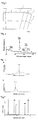
- Figs. 4 and 5 show the peak charts of the x-ray diffraction intensity with a solid line for the sample No. 1 and FIG. 6 shows the peak chart for the sample No. 15.
- polishing processing by machine polishing and ion milling was carried out for observing each coating layer 3 having the layered structure shown in Tables 3 and 4 by using the transmission electron microscope (TEM) and a cross section was exposed.
- the micro structure state of each layer observed in approximately perpendicular direction to the cross section of each layer was observed and the thickness of the layer was measured.
- the atom types existing in the center of the interlayer were confirmed and the composition was analyzed by energy dispersive spectroscopy (EDS) or electron energy-loss spectroscopy (EELS).
- EDS energy dispersive spectroscopy
- EELS electron energy-loss spectroscopy
- Evaluation item the number of impacts at the time of occurrence of cracking
- the coating layer of each cutting edge was observed with a microscope to determine whether or not the coating layer is peeled.
Landscapes
- Chemical & Material Sciences (AREA)
- Mechanical Engineering (AREA)
- Chemical Kinetics & Catalysis (AREA)
- Engineering & Computer Science (AREA)
- Materials Engineering (AREA)
- Metallurgy (AREA)
- Organic Chemistry (AREA)
- General Chemical & Material Sciences (AREA)
- Inorganic Chemistry (AREA)
- Chemical Vapour Deposition (AREA)
- Cutting Tools, Boring Holders, And Turrets (AREA)
- Inorganic Compounds Of Heavy Metals (AREA)
- Compounds Of Alkaline-Earth Elements, Aluminum Or Rare-Earth Metals (AREA)
Claims (9)
- Élément recouvert en surface (1) pourvu d'une couche de revêtement (3) qui a une structure stratifiée et est disposée sur la surface d'un substrat (2), la couche de revêtement (3) comprenant :une couche de carbonitrure de titane (TiCN) (4) ;une couche intercalaire (5) adhérant sans interruption à la couche de carbonitrure de titane (TiCN) (4), la couche intercalaire (5) étant composée de titane, d'aluminium, de carbone et d'oxygène ou composée de titane, d'aluminium, de carbone, d'oxygène et d'azote et ayant une épaisseur moyenne de 0,5 à 30 nm ; etune couche d'oxyde d'aluminium de structure cristalline de type α (Al2O3 de type α) (9) adhérant à la couche intercalaire,la teneur en oxygène au centre de la couche intercalaire (5) dans la direction de l'épaisseur étant de 15 à 40 % en atomes, etla teneur en atomes de titane au centre de la couche intercalaire (5) dans la direction de l'épaisseur étant de 20 à 40 % en atomes et la teneur en atomes d'aluminium étant de 5 à 15 % en atomes.
- Élément recouvert en surface (1) selon la revendication 1, dans lequel relativement aux pics de diffraction d'une analyse par diffraction des rayons X pour l'élément recouvert en surface (1), dans le cas où θt est défini comme la valeur 2θ d'un pic de diffraction attribué au plan (200) de TiCN ; θt0 est défini comme la valeur 2θ d'un pic de diffraction attribué au plan (200) de TiCN décrit dans la carte JCPDS ; θa(hkl) est défini comme la valeur 2θ d'un pic de diffraction attribué aux plans (012), (104), (110) et (113) de l'Al2O3 de structure cristalline de type α, l'indice hkl représentant un des plans cristallins (012), (104), (110) et (113) ; et θa0(hkl) est défini comme la valeur 2θ d'un pic de diffraction attribué aux plans (012), (104), (110) et (113) de l'Al2O3 de structure cristalline de type α décrits dans la carte JCPDS ; et Δθz(hkl) se situe dans une gamme de -0,2° à 0,2° pour tous les plans cristallins, Δθz(hkl) (= Δθt - Δθa(hkl)) étant la différence entre Δθt et Δθa(hkl), Δθt (= θt - θt0) étant la différence entre θt et θt0, et Δθa(hkl) (= θa(hkl) - θa0(hkl)) étant la différence entre θa(hkl) et θa0(hkl).
- Élément recouvert en surface (1) selon la revendication 2, dans lequel Δθz(012) pour le plan (012) se situe dans une gamme de -0,2° à 0°.
- Élément recouvert en surface (1) selon une des revendications 1 à 3, dans lequel si la différence entre θa(012) et θa0(012) est corrigée pour être nulle, l'angle θa(116) est inférieur à l'angle θa0(116).
- Élément recouvert en surface (1) selon la revendication 4, dans lequel θa(116) est supérieur de 31,8° à 31,9° à θa(012).
- Élément recouvert en surface (1) selon la revendication 4 ou 5, dans lequel les angles θa(104), θa(110), θa(113) et θa(024) sont plus grands que les angles respectifs θa0(104), θa0(110), θa0(113) et θa0(024).
- Élément recouvert en surface (1) selon une des revendications 4 à 6, dans lequel la couche d'oxyde d'aluminium de type α (9) est constituée de cristaux colonnaires étendus dans la direction de l'épaisseur.
- Élément recouvert en surface (1) selon la revendication 1, dans lequel la couche d'oxyde d'aluminium (9) est composée de cristaux d'oxyde d'aluminium de type α.
- Outil de coupe pourvu de l'élément recouvert en surface (1) selon une des revendications 1 à 8.
Applications Claiming Priority (4)
| Application Number | Priority Date | Filing Date | Title |
|---|---|---|---|
| JP2008045559 | 2008-02-27 | ||
| JP2008083955 | 2008-03-27 | ||
| JP2008113490 | 2008-04-24 | ||
| PCT/JP2009/053389 WO2009107648A1 (fr) | 2008-02-27 | 2009-02-25 | Organe à surface revêtue et outil de coupe |
Publications (3)
| Publication Number | Publication Date |
|---|---|
| EP2251122A1 EP2251122A1 (fr) | 2010-11-17 |
| EP2251122A4 EP2251122A4 (fr) | 2014-07-30 |
| EP2251122B1 true EP2251122B1 (fr) | 2016-04-13 |
Family
ID=41016037
Family Applications (1)
| Application Number | Title | Priority Date | Filing Date |
|---|---|---|---|
| EP09714933.0A Active EP2251122B1 (fr) | 2008-02-27 | 2009-02-25 | Organe à surface revêtue et outil de coupe |
Country Status (5)
| Country | Link |
|---|---|
| US (1) | US8449992B2 (fr) |
| EP (1) | EP2251122B1 (fr) |
| JP (2) | JP5111600B2 (fr) |
| CN (1) | CN101959631B (fr) |
| WO (1) | WO2009107648A1 (fr) |
Families Citing this family (37)
| Publication number | Priority date | Publication date | Assignee | Title |
|---|---|---|---|---|
| DE102009001675A1 (de) * | 2009-03-19 | 2010-09-23 | Eberhard-Karls-Universität Tübingen | Schneidwerkzeug |
| JP5715570B2 (ja) * | 2009-11-06 | 2015-05-07 | 株式会社タンガロイ | 被覆工具 |
| JP2011152602A (ja) * | 2010-01-27 | 2011-08-11 | Mitsubishi Materials Corp | 硬質被覆層がすぐれた耐欠損性を発揮する表面被覆切削工具 |
| JP5693039B2 (ja) * | 2010-04-27 | 2015-04-01 | 京セラ株式会社 | 表面被覆部材 |
| JP5472529B2 (ja) * | 2011-03-31 | 2014-04-16 | 日立ツール株式会社 | 硬質皮膜被覆部材及びそれを具備する刃先交換式回転工具 |
| CN103501940B (zh) * | 2011-04-28 | 2015-10-14 | 京瓷株式会社 | 切削工具 |
| US8524360B2 (en) | 2011-08-29 | 2013-09-03 | Kennametal Inc. | Cutting insert with a titanium oxycarbonitride coating and method for making the same |
| ES2567039T5 (es) * | 2011-09-16 | 2019-07-03 | Walter Ag | Herramienta de corte revestida con alúmina alfa que contiene azufre |
| CN103084598A (zh) * | 2011-10-31 | 2013-05-08 | 三菱综合材料株式会社 | 硬质包覆层发挥优异的耐崩刀性的表面包覆切削工具 |
| CN103128325A (zh) * | 2011-11-30 | 2013-06-05 | 三菱综合材料株式会社 | 硬质包覆层发挥优异的耐崩刀性的表面包覆切削工具 |
| EP2604720A1 (fr) * | 2011-12-14 | 2013-06-19 | Sandvik Intellectual Property Ab | Outil de coupe revêtu et son procédé de fabrication |
| JP5838789B2 (ja) * | 2011-12-22 | 2016-01-06 | 三菱マテリアル株式会社 | 硬質被覆層が高速断続切削ですぐれた耐チッピング性を発揮する表面被覆切削工具 |
| JP5850402B2 (ja) * | 2012-02-16 | 2016-02-03 | 三菱マテリアル株式会社 | 硬質被覆層がすぐれた耐チッピング性を発揮する表面被覆切削工具 |
| WO2014002948A1 (fr) | 2012-06-29 | 2014-01-03 | 住友電工ハードメタル株式会社 | Outil de coupe pour revêtement de surface |
| JP5892473B2 (ja) * | 2012-09-13 | 2016-03-23 | 三菱マテリアル株式会社 | 硬質被覆層が高速断続切削加工ですぐれた耐剥離性、耐チッピング性を発揮する表面被覆切削工具 |
| KR102056206B1 (ko) | 2012-10-01 | 2019-12-16 | 미츠비시 히타치 쓰루 가부시키가이샤 | 경질 피막 피복 공구 및 그 제조 방법 |
| US9849516B2 (en) * | 2012-12-21 | 2017-12-26 | Sandvik Intellectual Property Ab | Coated cutting tool and method for manufacturing the same |
| US9371580B2 (en) * | 2013-03-21 | 2016-06-21 | Kennametal Inc. | Coated body wherein the coating scheme includes a coating layer of TiAl2O3 and method of making the same |
| US9956667B2 (en) * | 2013-06-14 | 2018-05-01 | Sandvik Intellectual Property Ab | Coated cutting tool |
| EP3040143B1 (fr) * | 2013-08-27 | 2020-02-12 | Kyocera Corporation | Outil revêtu |
| RU2643754C2 (ru) * | 2013-11-08 | 2018-02-05 | Тунгалой Корпорейшн | Режущий инструмент с износостойким покрытием |
| KR101536462B1 (ko) * | 2013-12-23 | 2015-07-24 | 한국야금 주식회사 | 난삭재 및 주철가공 절삭공구용 피막 |
| EP3100806B1 (fr) * | 2014-01-27 | 2020-05-06 | Tungaloy Corporation | Outil de coupe revêtu |
| US10202688B2 (en) * | 2014-03-22 | 2019-02-12 | Kyocera Corporation | Coated tool and cutting tool |
| US9719175B2 (en) | 2014-09-30 | 2017-08-01 | Kennametal Inc. | Multilayer structured coatings for cutting tools |
| RU2704949C2 (ru) * | 2014-12-19 | 2019-10-31 | Сандвик Интеллекчуал Проперти Аб | Режущий инструмент с хогф-покрытием |
| JP6533286B2 (ja) * | 2015-04-27 | 2019-06-19 | 京セラ株式会社 | 被覆部材 |
| WO2017061144A1 (fr) * | 2015-10-09 | 2017-04-13 | 住友電工ハードメタル株式会社 | Outil de découpe avec revêtement de surface |
| CN108290223B (zh) * | 2015-11-28 | 2019-12-24 | 京瓷株式会社 | 切削工具 |
| JP6210346B1 (ja) * | 2016-11-02 | 2017-10-11 | 株式会社タンガロイ | 被覆切削工具 |
| CN108472739B (zh) * | 2016-12-09 | 2020-11-27 | 住友电工硬质合金株式会社 | 表面被覆切削工具 |
| JP6703311B2 (ja) | 2018-01-26 | 2020-06-03 | 株式会社タンガロイ | 被覆切削工具 |
| JP6999585B2 (ja) * | 2019-01-18 | 2022-01-18 | 株式会社タンガロイ | 被覆切削工具 |
| JP7055761B2 (ja) * | 2019-02-15 | 2022-04-18 | 株式会社タンガロイ | 被覆切削工具 |
| JP7473883B2 (ja) * | 2020-03-25 | 2024-04-24 | 三菱マテリアル株式会社 | 表面被覆切削工具 |
| CN118202083A (zh) * | 2021-11-16 | 2024-06-14 | 瓦尔特公开股份有限公司 | 中温CVD α氧化铝涂层 |
| CN116770293A (zh) * | 2023-06-21 | 2023-09-19 | 燕山大学 | 一种空气气氛下在磨料表面镀覆氮氧化钛或氮化钛的方法 |
Family Cites Families (23)
| Publication number | Priority date | Publication date | Assignee | Title |
|---|---|---|---|---|
| JPH0780083B2 (ja) * | 1986-09-30 | 1995-08-30 | 三菱マテリアル株式会社 | 安定した使用寿命を示す表面被覆硬質合金製切削工具 |
| SE501527C2 (sv) * | 1992-12-18 | 1995-03-06 | Sandvik Ab | Sätt och alster vid beläggning av ett skärande verktyg med ett aluminiumoxidskikt |
| JP3236903B2 (ja) | 1993-10-13 | 2001-12-10 | 三菱マテリアル株式会社 | 表面被覆切削工具 |
| US5920760A (en) * | 1994-05-31 | 1999-07-06 | Mitsubishi Materials Corporation | Coated hard alloy blade member |
| JPH10237649A (ja) * | 1997-02-20 | 1998-09-08 | Mitsubishi Materials Corp | 耐欠損性に優れた表面被覆切削工具 |
| JPH1177407A (ja) | 1997-09-04 | 1999-03-23 | Hitachi Metals Ltd | 酸化アルミニウム被覆工具 |
| US6805944B2 (en) * | 2001-03-26 | 2004-10-19 | Mitsubishi Materials Corporation | Coated cemented carbide cutting tool |
| JP2003025114A (ja) * | 2001-07-16 | 2003-01-29 | Toshiba Tungaloy Co Ltd | 酸化アルミニウム被覆工具 |
| JP3578121B2 (ja) * | 2001-08-06 | 2004-10-20 | 三菱マテリアル神戸ツールズ株式会社 | 耐摩耗被覆層がすぐれた耐熱塑性変形性を発揮する表面被覆超硬合金製切削工具 |
| US6733874B2 (en) * | 2001-08-31 | 2004-05-11 | Mitsubishi Materials Corporation | Surface-coated carbide alloy cutting tool |
| SE525581C2 (sv) * | 2002-05-08 | 2005-03-15 | Seco Tools Ab | Skär belagt med aluminiumoxid framställt med CVD |
| JP3971293B2 (ja) * | 2002-08-08 | 2007-09-05 | 株式会社神戸製鋼所 | 耐摩耗性および耐熱性に優れた積層皮膜およびその製造方法、並びに耐摩耗性および耐熱性に優れた積層皮膜被覆工具 |
| EP2865784A1 (fr) * | 2002-08-08 | 2015-04-29 | Kabushiki Kaisha Kobe Seiko Sho (Kobe Steel, Ltd.) | Procédé de production de revêtement d'alumine composée principalement d'une structure cristalline de type alpha |
| SE526526C3 (sv) * | 2003-04-01 | 2005-10-26 | Sandvik Intellectual Property | Sätt att belägga skär med A1203 samt ett med A1203 belagt skärverktyg |
| SE526602C2 (sv) * | 2003-10-27 | 2005-10-18 | Seco Tools Ab | Belagt skär för grovsvarvning |
| US7455918B2 (en) * | 2004-03-12 | 2008-11-25 | Kennametal Inc. | Alumina coating, coated product and method of making the same |
| CN100473483C (zh) * | 2004-08-11 | 2009-04-01 | 三菱综合材料株式会社 | 表面被覆金属陶瓷制切削工具 |
| JP2006055950A (ja) | 2004-08-20 | 2006-03-02 | Tungaloy Corp | 被覆切削工具 |
| SE528431C2 (sv) * | 2004-11-05 | 2006-11-14 | Seco Tools Ab | Med aluminiumoxid belagt skärverktygsskär samt metod att framställa detta |
| SE528430C2 (sv) * | 2004-11-05 | 2006-11-14 | Seco Tools Ab | Med aluminiumoxid belagt skärverktygsskär samt metod att framställa detta |
| US7803464B2 (en) * | 2004-12-27 | 2010-09-28 | Sumitomo Electric Hardmetal Corp. | Surface-coated cutting tool |
| JP4518260B2 (ja) * | 2005-01-21 | 2010-08-04 | 三菱マテリアル株式会社 | 硬質被覆層が高速断続切削加工ですぐれた耐チッピング性を発揮する表面被覆サーメット製切削工具 |
| SE529051C2 (sv) * | 2005-09-27 | 2007-04-17 | Seco Tools Ab | Skärverktygsskär belagt med aluminiumoxid |
-
2009
- 2009-02-25 WO PCT/JP2009/053389 patent/WO2009107648A1/fr not_active Ceased
- 2009-02-25 JP JP2010500710A patent/JP5111600B2/ja active Active
- 2009-02-25 CN CN200980106446XA patent/CN101959631B/zh active Active
- 2009-02-25 EP EP09714933.0A patent/EP2251122B1/fr active Active
- 2009-02-25 US US12/919,740 patent/US8449992B2/en active Active
-
2012
- 2012-07-27 JP JP2012166460A patent/JP5460790B2/ja active Active
Also Published As
| Publication number | Publication date |
|---|---|
| CN101959631B (zh) | 2012-09-26 |
| US8449992B2 (en) | 2013-05-28 |
| JP5111600B2 (ja) | 2013-01-09 |
| JP5460790B2 (ja) | 2014-04-02 |
| WO2009107648A1 (fr) | 2009-09-03 |
| EP2251122A1 (fr) | 2010-11-17 |
| US20100330360A1 (en) | 2010-12-30 |
| EP2251122A4 (fr) | 2014-07-30 |
| JP2012254523A (ja) | 2012-12-27 |
| CN101959631A (zh) | 2011-01-26 |
| JPWO2009107648A1 (ja) | 2011-07-07 |
Similar Documents
| Publication | Publication Date | Title |
|---|---|---|
| US8449992B2 (en) | Surface-coated member and cutting tool | |
| EP2006040B1 (fr) | Outil de découpage, procédé de production dudit outil de découpage et procédé de découpage | |
| KR102068855B1 (ko) | 코팅된 절삭 공구 및 이의 제조 방법 | |
| EP3747575B1 (fr) | Outil revêtu, et outil de coupe équipé de celui-ci | |
| CN108698136A (zh) | 覆盖工具 | |
| WO2017217012A1 (fr) | Outil de découpe avec revêtement de surface | |
| KR20190119088A (ko) | 금속, 초경합금, 도성합금 또는 세라믹으로 이루어지고 경질 재료로 코팅된 물품 및 이러한 물품의 제조 방법 | |
| KR102312226B1 (ko) | 표면 피복 절삭 공구 및 그 제조 방법 | |
| WO2011052767A1 (fr) | Outil de coupe revêtu en surface avec excellente résistance à l'écaillage | |
| EP3747577B1 (fr) | Outil revêtu et outil de coupe équipé de celui-ci | |
| JP4832108B2 (ja) | 表面被覆切削工具 | |
| KR102731820B1 (ko) | 피복 공구 | |
| JP4351521B2 (ja) | 表面被覆切削工具 | |
| JP2004291162A (ja) | 表面被覆切削工具 | |
| KR102746694B1 (ko) | 피복 공구 | |
| EP3747576A1 (fr) | Outil revêtu, et outil de coupe équipé de celui-ci | |
| JP4484500B2 (ja) | 表面被覆切削工具 | |
| JP7851412B2 (ja) | 被覆工具および切削工具 | |
| JP4663248B2 (ja) | 表面被覆切削工具 | |
| JP4936742B2 (ja) | 表面被覆工具および切削工具 | |
| JP4817799B2 (ja) | 表面被覆体 | |
| JP4936741B2 (ja) | 表面被覆工具および切削工具 | |
| WO2021245784A1 (fr) | Outil de coupe | |
| WO2021245783A1 (fr) | Outil de coupe |
Legal Events
| Date | Code | Title | Description |
|---|---|---|---|
| PUAI | Public reference made under article 153(3) epc to a published international application that has entered the european phase |
Free format text: ORIGINAL CODE: 0009012 |
|
| 17P | Request for examination filed |
Effective date: 20100901 |
|
| AK | Designated contracting states |
Kind code of ref document: A1 Designated state(s): AT BE BG CH CY CZ DE DK EE ES FI FR GB GR HR HU IE IS IT LI LT LU LV MC MK MT NL NO PL PT RO SE SI SK TR |
|
| AX | Request for extension of the european patent |
Extension state: AL BA RS |
|
| DAX | Request for extension of the european patent (deleted) | ||
| A4 | Supplementary search report drawn up and despatched |
Effective date: 20140630 |
|
| RIC1 | Information provided on ipc code assigned before grant |
Ipc: B23B 27/14 20060101AFI20140624BHEP Ipc: C23C 16/36 20060101ALI20140624BHEP Ipc: C23C 28/00 20060101ALI20140624BHEP Ipc: C23C 28/02 20060101ALI20140624BHEP |
|
| 17Q | First examination report despatched |
Effective date: 20150423 |
|
| GRAP | Despatch of communication of intention to grant a patent |
Free format text: ORIGINAL CODE: EPIDOSNIGR1 |
|
| INTG | Intention to grant announced |
Effective date: 20151001 |
|
| GRAS | Grant fee paid |
Free format text: ORIGINAL CODE: EPIDOSNIGR3 |
|
| GRAA | (expected) grant |
Free format text: ORIGINAL CODE: 0009210 |
|
| AK | Designated contracting states |
Kind code of ref document: B1 Designated state(s): AT BE BG CH CY CZ DE DK EE ES FI FR GB GR HR HU IE IS IT LI LT LU LV MC MK MT NL NO PL PT RO SE SI SK TR |
|
| REG | Reference to a national code |
Ref country code: GB Ref legal event code: FG4D |
|
| REG | Reference to a national code |
Ref country code: AT Ref legal event code: REF Ref document number: 789576 Country of ref document: AT Kind code of ref document: T Effective date: 20160415 Ref country code: CH Ref legal event code: EP |
|
| REG | Reference to a national code |
Ref country code: IE Ref legal event code: FG4D |
|
| REG | Reference to a national code |
Ref country code: DE Ref legal event code: R096 Ref document number: 602009037747 Country of ref document: DE |
|
| REG | Reference to a national code |
Ref country code: LT Ref legal event code: MG4D |
|
| REG | Reference to a national code |
Ref country code: AT Ref legal event code: MK05 Ref document number: 789576 Country of ref document: AT Kind code of ref document: T Effective date: 20160413 |
|
| REG | Reference to a national code |
Ref country code: NL Ref legal event code: MP Effective date: 20160413 |
|
| PG25 | Lapsed in a contracting state [announced via postgrant information from national office to epo] |
Ref country code: FI Free format text: LAPSE BECAUSE OF FAILURE TO SUBMIT A TRANSLATION OF THE DESCRIPTION OR TO PAY THE FEE WITHIN THE PRESCRIBED TIME-LIMIT Effective date: 20160413 Ref country code: LT Free format text: LAPSE BECAUSE OF FAILURE TO SUBMIT A TRANSLATION OF THE DESCRIPTION OR TO PAY THE FEE WITHIN THE PRESCRIBED TIME-LIMIT Effective date: 20160413 Ref country code: NL Free format text: LAPSE BECAUSE OF FAILURE TO SUBMIT A TRANSLATION OF THE DESCRIPTION OR TO PAY THE FEE WITHIN THE PRESCRIBED TIME-LIMIT Effective date: 20160413 Ref country code: PL Free format text: LAPSE BECAUSE OF FAILURE TO SUBMIT A TRANSLATION OF THE DESCRIPTION OR TO PAY THE FEE WITHIN THE PRESCRIBED TIME-LIMIT Effective date: 20160413 Ref country code: NO Free format text: LAPSE BECAUSE OF FAILURE TO SUBMIT A TRANSLATION OF THE DESCRIPTION OR TO PAY THE FEE WITHIN THE PRESCRIBED TIME-LIMIT Effective date: 20160713 |
|
| PG25 | Lapsed in a contracting state [announced via postgrant information from national office to epo] |
Ref country code: PT Free format text: LAPSE BECAUSE OF FAILURE TO SUBMIT A TRANSLATION OF THE DESCRIPTION OR TO PAY THE FEE WITHIN THE PRESCRIBED TIME-LIMIT Effective date: 20160816 Ref country code: GR Free format text: LAPSE BECAUSE OF FAILURE TO SUBMIT A TRANSLATION OF THE DESCRIPTION OR TO PAY THE FEE WITHIN THE PRESCRIBED TIME-LIMIT Effective date: 20160714 Ref country code: SE Free format text: LAPSE BECAUSE OF FAILURE TO SUBMIT A TRANSLATION OF THE DESCRIPTION OR TO PAY THE FEE WITHIN THE PRESCRIBED TIME-LIMIT Effective date: 20160413 Ref country code: HR Free format text: LAPSE BECAUSE OF FAILURE TO SUBMIT A TRANSLATION OF THE DESCRIPTION OR TO PAY THE FEE WITHIN THE PRESCRIBED TIME-LIMIT Effective date: 20160413 Ref country code: LV Free format text: LAPSE BECAUSE OF FAILURE TO SUBMIT A TRANSLATION OF THE DESCRIPTION OR TO PAY THE FEE WITHIN THE PRESCRIBED TIME-LIMIT Effective date: 20160413 Ref country code: ES Free format text: LAPSE BECAUSE OF FAILURE TO SUBMIT A TRANSLATION OF THE DESCRIPTION OR TO PAY THE FEE WITHIN THE PRESCRIBED TIME-LIMIT Effective date: 20160413 Ref country code: AT Free format text: LAPSE BECAUSE OF FAILURE TO SUBMIT A TRANSLATION OF THE DESCRIPTION OR TO PAY THE FEE WITHIN THE PRESCRIBED TIME-LIMIT Effective date: 20160413 |
|
| PG25 | Lapsed in a contracting state [announced via postgrant information from national office to epo] |
Ref country code: BE Free format text: LAPSE BECAUSE OF FAILURE TO SUBMIT A TRANSLATION OF THE DESCRIPTION OR TO PAY THE FEE WITHIN THE PRESCRIBED TIME-LIMIT Effective date: 20160413 Ref country code: IT Free format text: LAPSE BECAUSE OF FAILURE TO SUBMIT A TRANSLATION OF THE DESCRIPTION OR TO PAY THE FEE WITHIN THE PRESCRIBED TIME-LIMIT Effective date: 20160413 |
|
| REG | Reference to a national code |
Ref country code: DE Ref legal event code: R097 Ref document number: 602009037747 Country of ref document: DE |
|
| PG25 | Lapsed in a contracting state [announced via postgrant information from national office to epo] |
Ref country code: CZ Free format text: LAPSE BECAUSE OF FAILURE TO SUBMIT A TRANSLATION OF THE DESCRIPTION OR TO PAY THE FEE WITHIN THE PRESCRIBED TIME-LIMIT Effective date: 20160413 Ref country code: RO Free format text: LAPSE BECAUSE OF FAILURE TO SUBMIT A TRANSLATION OF THE DESCRIPTION OR TO PAY THE FEE WITHIN THE PRESCRIBED TIME-LIMIT Effective date: 20160413 Ref country code: SK Free format text: LAPSE BECAUSE OF FAILURE TO SUBMIT A TRANSLATION OF THE DESCRIPTION OR TO PAY THE FEE WITHIN THE PRESCRIBED TIME-LIMIT Effective date: 20160413 Ref country code: DK Free format text: LAPSE BECAUSE OF FAILURE TO SUBMIT A TRANSLATION OF THE DESCRIPTION OR TO PAY THE FEE WITHIN THE PRESCRIBED TIME-LIMIT Effective date: 20160413 Ref country code: EE Free format text: LAPSE BECAUSE OF FAILURE TO SUBMIT A TRANSLATION OF THE DESCRIPTION OR TO PAY THE FEE WITHIN THE PRESCRIBED TIME-LIMIT Effective date: 20160413 |
|
| PLBE | No opposition filed within time limit |
Free format text: ORIGINAL CODE: 0009261 |
|
| STAA | Information on the status of an ep patent application or granted ep patent |
Free format text: STATUS: NO OPPOSITION FILED WITHIN TIME LIMIT |
|
| 26N | No opposition filed |
Effective date: 20170116 |
|
| PG25 | Lapsed in a contracting state [announced via postgrant information from national office to epo] |
Ref country code: SI Free format text: LAPSE BECAUSE OF FAILURE TO SUBMIT A TRANSLATION OF THE DESCRIPTION OR TO PAY THE FEE WITHIN THE PRESCRIBED TIME-LIMIT Effective date: 20160413 |
|
| PG25 | Lapsed in a contracting state [announced via postgrant information from national office to epo] |
Ref country code: MC Free format text: LAPSE BECAUSE OF FAILURE TO SUBMIT A TRANSLATION OF THE DESCRIPTION OR TO PAY THE FEE WITHIN THE PRESCRIBED TIME-LIMIT Effective date: 20160413 |
|
| REG | Reference to a national code |
Ref country code: CH Ref legal event code: PL |
|
| GBPC | Gb: european patent ceased through non-payment of renewal fee |
Effective date: 20170225 |
|
| PG25 | Lapsed in a contracting state [announced via postgrant information from national office to epo] |
Ref country code: CH Free format text: LAPSE BECAUSE OF NON-PAYMENT OF DUE FEES Effective date: 20170228 Ref country code: LI Free format text: LAPSE BECAUSE OF NON-PAYMENT OF DUE FEES Effective date: 20170228 |
|
| REG | Reference to a national code |
Ref country code: IE Ref legal event code: MM4A |
|
| REG | Reference to a national code |
Ref country code: FR Ref legal event code: ST Effective date: 20171031 |
|
| PG25 | Lapsed in a contracting state [announced via postgrant information from national office to epo] |
Ref country code: LU Free format text: LAPSE BECAUSE OF NON-PAYMENT OF DUE FEES Effective date: 20170225 |
|
| PG25 | Lapsed in a contracting state [announced via postgrant information from national office to epo] |
Ref country code: FR Free format text: LAPSE BECAUSE OF NON-PAYMENT OF DUE FEES Effective date: 20170228 |
|
| PG25 | Lapsed in a contracting state [announced via postgrant information from national office to epo] |
Ref country code: IE Free format text: LAPSE BECAUSE OF NON-PAYMENT OF DUE FEES Effective date: 20170225 Ref country code: GB Free format text: LAPSE BECAUSE OF NON-PAYMENT OF DUE FEES Effective date: 20170225 |
|
| PG25 | Lapsed in a contracting state [announced via postgrant information from national office to epo] |
Ref country code: MT Free format text: LAPSE BECAUSE OF NON-PAYMENT OF DUE FEES Effective date: 20170225 |
|
| PG25 | Lapsed in a contracting state [announced via postgrant information from national office to epo] |
Ref country code: HU Free format text: LAPSE BECAUSE OF FAILURE TO SUBMIT A TRANSLATION OF THE DESCRIPTION OR TO PAY THE FEE WITHIN THE PRESCRIBED TIME-LIMIT; INVALID AB INITIO Effective date: 20090225 |
|
| PG25 | Lapsed in a contracting state [announced via postgrant information from national office to epo] |
Ref country code: BG Free format text: LAPSE BECAUSE OF FAILURE TO SUBMIT A TRANSLATION OF THE DESCRIPTION OR TO PAY THE FEE WITHIN THE PRESCRIBED TIME-LIMIT Effective date: 20160413 |
|
| PG25 | Lapsed in a contracting state [announced via postgrant information from national office to epo] |
Ref country code: CY Free format text: LAPSE BECAUSE OF NON-PAYMENT OF DUE FEES Effective date: 20160413 |
|
| PG25 | Lapsed in a contracting state [announced via postgrant information from national office to epo] |
Ref country code: MK Free format text: LAPSE BECAUSE OF FAILURE TO SUBMIT A TRANSLATION OF THE DESCRIPTION OR TO PAY THE FEE WITHIN THE PRESCRIBED TIME-LIMIT Effective date: 20160413 |
|
| PG25 | Lapsed in a contracting state [announced via postgrant information from national office to epo] |
Ref country code: TR Free format text: LAPSE BECAUSE OF FAILURE TO SUBMIT A TRANSLATION OF THE DESCRIPTION OR TO PAY THE FEE WITHIN THE PRESCRIBED TIME-LIMIT Effective date: 20160413 |
|
| PG25 | Lapsed in a contracting state [announced via postgrant information from national office to epo] |
Ref country code: IS Free format text: LAPSE BECAUSE OF FAILURE TO SUBMIT A TRANSLATION OF THE DESCRIPTION OR TO PAY THE FEE WITHIN THE PRESCRIBED TIME-LIMIT Effective date: 20160813 |
|
| P01 | Opt-out of the competence of the unified patent court (upc) registered |
Effective date: 20230505 |
|
| PGFP | Annual fee paid to national office [announced via postgrant information from national office to epo] |
Ref country code: DE Payment date: 20241231 Year of fee payment: 17 |