EP2251178A2 - Dispositif pour échanger le cylindre à vis d'une extrudeuse - Google Patents
Dispositif pour échanger le cylindre à vis d'une extrudeuse Download PDFInfo
- Publication number
- EP2251178A2 EP2251178A2 EP10004842A EP10004842A EP2251178A2 EP 2251178 A2 EP2251178 A2 EP 2251178A2 EP 10004842 A EP10004842 A EP 10004842A EP 10004842 A EP10004842 A EP 10004842A EP 2251178 A2 EP2251178 A2 EP 2251178A2
- Authority
- EP
- European Patent Office
- Prior art keywords
- extrusion cylinder
- cylinder
- receiving means
- movement
- transport
- Prior art date
- Legal status (The legal status is an assumption and is not a legal conclusion. Google has not performed a legal analysis and makes no representation as to the accuracy of the status listed.)
- Granted
Links
- 238000001125 extrusion Methods 0.000 claims abstract description 112
- 238000006073 displacement reaction Methods 0.000 claims description 38
- 238000012546 transfer Methods 0.000 claims description 18
- 230000008859 change Effects 0.000 claims description 17
- 230000008878 coupling Effects 0.000 claims description 15
- 238000010168 coupling process Methods 0.000 claims description 15
- 238000005859 coupling reaction Methods 0.000 claims description 15
- 230000007246 mechanism Effects 0.000 claims description 13
- 238000007667 floating Methods 0.000 claims description 9
- 230000000903 blocking effect Effects 0.000 claims description 4
- 239000006163 transport media Substances 0.000 claims description 2
- 238000000034 method Methods 0.000 description 9
- 230000008569 process Effects 0.000 description 9
- 238000012545 processing Methods 0.000 description 5
- 230000005540 biological transmission Effects 0.000 description 4
- 238000006243 chemical reaction Methods 0.000 description 3
- 239000002826 coolant Substances 0.000 description 3
- 239000000463 material Substances 0.000 description 3
- 238000003860 storage Methods 0.000 description 3
- 230000004888 barrier function Effects 0.000 description 2
- 230000008901 benefit Effects 0.000 description 2
- 238000004140 cleaning Methods 0.000 description 2
- 238000010276 construction Methods 0.000 description 2
- 238000013461 design Methods 0.000 description 2
- 238000010586 diagram Methods 0.000 description 2
- 238000009434 installation Methods 0.000 description 2
- 238000004519 manufacturing process Methods 0.000 description 2
- 208000036829 Device dislocation Diseases 0.000 description 1
- 229910000831 Steel Inorganic materials 0.000 description 1
- 238000013459 approach Methods 0.000 description 1
- 239000004595 color masterbatch Substances 0.000 description 1
- 238000013329 compounding Methods 0.000 description 1
- 238000001514 detection method Methods 0.000 description 1
- 230000000694 effects Effects 0.000 description 1
- 238000005516 engineering process Methods 0.000 description 1
- 230000008921 facial expression Effects 0.000 description 1
- 230000035515 penetration Effects 0.000 description 1
- 230000009467 reduction Effects 0.000 description 1
- 230000006641 stabilisation Effects 0.000 description 1
- 238000011105 stabilization Methods 0.000 description 1
- 239000010959 steel Substances 0.000 description 1
- 239000012815 thermoplastic material Substances 0.000 description 1
- XLYOFNOQVPJJNP-UHFFFAOYSA-N water Substances O XLYOFNOQVPJJNP-UHFFFAOYSA-N 0.000 description 1
Images




Classifications
-
- B—PERFORMING OPERATIONS; TRANSPORTING
- B29—WORKING OF PLASTICS; WORKING OF SUBSTANCES IN A PLASTIC STATE IN GENERAL
- B29C—SHAPING OR JOINING OF PLASTICS; SHAPING OF MATERIAL IN A PLASTIC STATE, NOT OTHERWISE PROVIDED FOR; AFTER-TREATMENT OF THE SHAPED PRODUCTS, e.g. REPAIRING
- B29C48/00—Extrusion moulding, i.e. expressing the moulding material through a die or nozzle which imparts the desired form; Apparatus therefor
- B29C48/25—Component parts, details or accessories; Auxiliary operations
- B29C48/36—Means for plasticising or homogenising the moulding material or forcing it through the nozzle or die
- B29C48/50—Details of extruders
- B29C48/68—Barrels or cylinders
-
- B—PERFORMING OPERATIONS; TRANSPORTING
- B29—WORKING OF PLASTICS; WORKING OF SUBSTANCES IN A PLASTIC STATE IN GENERAL
- B29C—SHAPING OR JOINING OF PLASTICS; SHAPING OF MATERIAL IN A PLASTIC STATE, NOT OTHERWISE PROVIDED FOR; AFTER-TREATMENT OF THE SHAPED PRODUCTS, e.g. REPAIRING
- B29C48/00—Extrusion moulding, i.e. expressing the moulding material through a die or nozzle which imparts the desired form; Apparatus therefor
- B29C48/25—Component parts, details or accessories; Auxiliary operations
- B29C48/256—Exchangeable extruder parts
-
- B—PERFORMING OPERATIONS; TRANSPORTING
- B29—WORKING OF PLASTICS; WORKING OF SUBSTANCES IN A PLASTIC STATE IN GENERAL
- B29C—SHAPING OR JOINING OF PLASTICS; SHAPING OF MATERIAL IN A PLASTIC STATE, NOT OTHERWISE PROVIDED FOR; AFTER-TREATMENT OF THE SHAPED PRODUCTS, e.g. REPAIRING
- B29C48/00—Extrusion moulding, i.e. expressing the moulding material through a die or nozzle which imparts the desired form; Apparatus therefor
- B29C48/25—Component parts, details or accessories; Auxiliary operations
- B29C48/256—Exchangeable extruder parts
- B29C48/2562—Mounting or handling of the die
-
- B—PERFORMING OPERATIONS; TRANSPORTING
- B29—WORKING OF PLASTICS; WORKING OF SUBSTANCES IN A PLASTIC STATE IN GENERAL
- B29C—SHAPING OR JOINING OF PLASTICS; SHAPING OF MATERIAL IN A PLASTIC STATE, NOT OTHERWISE PROVIDED FOR; AFTER-TREATMENT OF THE SHAPED PRODUCTS, e.g. REPAIRING
- B29C48/00—Extrusion moulding, i.e. expressing the moulding material through a die or nozzle which imparts the desired form; Apparatus therefor
- B29C48/03—Extrusion moulding, i.e. expressing the moulding material through a die or nozzle which imparts the desired form; Apparatus therefor characterised by the shape of the extruded material at extrusion
Definitions
- the invention relates to a device for changing an extrusion cylinder of an extruder, which extrusion cylinder from a plurality of cylinder sections and at least one in-cylinder screw element, which is to be coupled for extrusion with a drive unit of the extruder consists.
- Extruders are used for the processing and processing of a wide variety of materials, for example in color masterbatch production or compounding processes, as well as in the processing of thermoplastic materials. Smaller batch sizes, for example in the range from 25 to 1000 kg, play an increasing role in almost all areas. With a product change would be in view of an optimal work process and an optimal work result, a conversion of the extrusion cylinder together with the or in him screw elements required, coupled with an intensive cleaning of those cylinder parts or screw parts, which are also used in the context of processing the new materials can.
- a conversion requires a complete disassembly of the segmented cylinder sections and screw sections existing extrusion cylinder, which takes a long time, usually 1 - 2 days.
- the invention is based on the problem of specifying a possibility that allows a much faster conversion of an extruder.
- a quick-change device for an extrusion cylinder for solving this problem, which is characterized in that a frame or frame-like carrier carrying the extrusion cylinder is provided, via which the extrusion cylinder can be held on a receiving means provided on the extruder and on a movable transport means atecsmechnismus is provided on the receiving means and / or on the means of transport, which allows for a change of the complete extrusion cylinder from the receiving means to the transport and vice versa required movement of the extrusion cylinder in a direction perpendicular to the cylinder axis.
- the quick-change device comprises a frame or frame-like support on which the complete extrusion cylinder together with the screw element located in it and preferably also the entire water supply, power supply and the control lines is constructed. That is, on this standardized carrier, which is always the same for different cylinders built on it, the complete process unit including all supply and control lines is provided.
- This carrier is now according to the invention with an extruder-side receiving means and with a movable relative to the extruder transport detachably connectable, where he can be handed over between the two. For this purpose, a movement mechanism on the receiving means and / or on the means of transport is provided which allows this transfer or the change of the entire process unit.
- the receiving means itself is designed to be movable for a movement of the extrusion cylinder perpendicular to its longitudinal axis from a first position in which the extrusion cylinder with the screw elements is in the extrusion direction to a second position in which the transfer to the transport means takes place be. That is, the receiving means itself is moved overall.
- a corresponding part of the receiving means for the realization of the movement mechanism may be movable.
- the movement itself can be different. It is conceivable to design the receiving means itself or a part thereof to be pivotable about an axis lying parallel to the cylinder axis. That is, the cylinder change is effected by a sideways pivoting of the entire process unit to the transport, which takes over the carrier together with the process unit during the pivoting movement or at the end of the pivoting movement.
- the pivoting operation can also be controlled via a hydraulically or pneumatically controlled cylinder.
- the receiving means itself or a part thereof via a parallelogram linkage with two each forming a pivot axis shafts, of which at least one is driven by a motor and on which linkage at least two brackets are provided for the carrier, perpendicular is pivotable to the cylinder axis.
- This embodiment also allows a sideways pivoting for carrier and thus cylinder transfer, but using two pivot axes and a parallelogram linkage, which - unlike the single-axis solution - allows sideways movement while maintaining constant horizontal alignment of the extrusion cylinder.
- the receiving means itself or a part thereof is horizontally displaceable via a linear guide system, in which case a lifting device is provided for vertically moving the receiving means or the part in the region of the receiving means itself, or such a lifting device on Transport means is provided which allows a vertical movement of the transport medium side recorded extrusion cylinder.
- the lifting device which may be provided as described either on the receiving means or on the means of transport is required in this case for the transfer or for taking over the carrier together with cylinder, depending on the arrangement of the lifting device either the receiving means itself for recording or transferring can be raised or lowered, or the corresponding movable part thereof, or can be raised or lowered at an arrangement of the lifting device on the transport of the local support receiving area to take over the carrier coming from the receiving means or to transfer to this.
- the transport means side provided movement means is expediently a linear displacement device which can be moved relative to the receiving means. If, for example, the receiving means is pivotable, the transport means-side displacement device undercuts the carrier, whereafter the receiving means pivots and deposits the carrier on the displacement device, after which it is retracted again onto the transport means. If the movement mechanism on the receiving means is likewise a linear displacement system, then both linear systems can engage in one another to change the carrier, for which purpose at least one is moveable via a lifting device, primarily that of the means of transport to take over or transfer the carrier , About this lifting device can also be done a height adjustment.
- the disassembly of the "old" extrusion cylinder and in a second one is via the inventive device in a first change step Step the assembly of the "new" extrusion cylinder on the extruder possible.
- the means of transport it is expedient for the means of transport to have two receptacles for one extrusion cylinder each having one or a common movement device. That is, the transported to the extruder transport in a first recording the "new" extrusion cylinder with it and takes in a first step the "old" extrusion cylinder in the second recording, after which immediately removed the "new" extrusion cylinder from the first recording and can be handed over.
- the two receptacles can be arranged one behind the other in the longitudinal direction.
- the disassembled "old" extrusion cylinder would be introduced into the first receptacle via its support, whereafter the transport means would be manually or automatically displaced until it is correctly positioned again and the "new" extrusion cylinder can be transferred from the second receptacle.
- the two receptacles one above the other and to make them vertically movable for positioning relative to the receiving means. So here is a paternoster-like vertical alternating operation realized.
- the free intake moves into the transfer position and picks up the "old" extrusion cylinder, after which the entire facial expressions move downward, for example, and the second, upper intake is moved to the transfer position with the "new" extrusion cylinder.
- both transport means are movable separately with respect to the extruder.
- a means of transport for example, be moved on the bottom side, so it is designed like a wagon and either roll or rail.
- the receiving means is expediently movable in the extrusion direction even for a displacement of the extrusion cylinder relative to the extruder for coupling or decoupling the worm element, or it has a displacement device enabling such a displacement. This makes it possible to move the extrusion cylinder in the extrusion direction until the worm shaft or shafts have moved out of the coupling sleeves and the gear lantern.
- the coupling sleeves are movable, they can be displaced on the gear shafts or worm shafts until they are disengaged, in this case the gear flange is made "open", so that the sideways movement of the extrusion cylinder can be accomplished without any longitudinal displacement.
- an electrically or pneumatically or hydraulically controlled cylinder which moves the corresponding longitudinally displaceably guided receiving means or the displacement device.
- the movement is initiated, for example, by actuation of a shift key, which must be pressed continuously until the end position, which allows sideways movement, is taken, which is e.g. is detected via a limit switch, which stops the further control of the cylinder.
- This barrier means may e.g. in the form of a pin or bolt, which is guided in a corresponding guide, be realized, said pin is released only when the end position is reached.
- the carrier including the extrusion cylinder on the receiving means and / or means of transport are expediently means for fixing the carrier provided, in particular in the form of clamping or latching mountings or in the form of engagement holders holding by positive engagement.
- These fixing devices serve not only for locking, but also for determining the correct positioning of the carrier on the receiving means or on the transport means, after the devices can only be closed or interlock when the carrier is in the correct position.
- At least one sensor should be provided for detecting the positioning of the transporting means relative to the receiving means, wherein the transfer operation of the extrusion cylinder takes place as a function of the sensor signal.
- This sensor can e.g. be designed as a button, which is then automatically actuated via the means of transport when this is correctly positioned, is also conceivable a light barrier or the like. If the sensor gives the detection signal, the automatic alternating operation can take place, it is thus released control technology.
- the swing-out mechanism can only be actuated by actuation of a switch or, if the sensor signal is present, the clamping or latching supports serving as support fixing are automatically opened on the receiving means or on the transport means via correspondingly actuated actuators, then that the carrier is released, etc.
- the extrusion cylinder is mounted floating on the support, that is, the cylinder unit itself is movable relative to the carrier fixed in the x- and y-direction both for the orientation for coupling, as well as for temperature-induced elongations during operation to be able to catch.
- the floating storage is expediently realized by means of two plates, one of which is fixedly connected to the carrier and the second plate is connected to the extrusion cylinder and interposed with respect to the first plate, for example Balls is movable, wherein a locking device is provided via a movable locking member is provided which is engageable with the need for blocking the mobility of the plate located on the extrusion cylinder with this.
- the extrusion cylinder is thus movable with respect to the carrier locked on the receiving means, so it can be moved manually for alignment something.
- a locking device is provided which serves to block the mobility, which is necessary when changing to avoid that the extrusion cylinder slips when pivoting with respect to the carrier.
- the locking member may be an opening in the extrusion cylinder associated plate passing through bolt with a diameter substantially matched to the opening clamping portion and a contrast reduced in diameter release portion, which bolt in the unlocked position with the release portion in the opening and in the blocking position can be positioned with the clamping portion in the aperture, this advantageously takes place via an electrically or pneumatically controlled actuator cylinder.
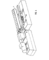
- Fig. 1 shows an extruder 1 with a motor 2 with downstream gearbox 3 and an extrusion cylinder 4 consisting of a plurality of cylinder sections 5, in the interior of which in the example shown two screw elements are received in corresponding bores via the transmission 3, with which they have a not shown in detail However, coupled well-known coupling are driven.
- the extrusion cylinder 4 is constructed together with all the required coolant, power and control lines, which are laid in a corresponding installation box 6 on a frame - or frame-like support 7, which is a quasi-standardized component, that is, everyone on the transmission 3 connectable extrusion cylinder is constructed on such an identical running carrier.
- the laid in the line box 6 lines are guided or designed or coupled so that as few connections with the located in the supply and control cabinets 8 coolant and power supply facilities and control devices are to be connected. Only a coolant connection, a power supply connection, is preferred and a control line connection, that is, the extrusion cylinder 4 is to be connected to the resource systems via only three connectors. Not shown in detail are any arranged on the cylinder attachments such as dosing or side feeds that serve the supply of material. These are to be dismantled before the cylinder change.
- the carrier 7 is accommodated on a receiving means 10 arranged on the machine frame 9 of the extruder 1.
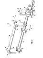
- This receiving means 10 which in detail in Fig. 2 is shown, consists of a guided in two bearings 11 shaft 12 which can be rotated by a motor 13.
- two radially and vertically projecting cheeks 14 are provided in the example shown, which are interconnected via an intermediate support 15 for reasons of stabilization.
- At the upper end of the cheeks form-fitting interventions 16 are provided which cooperate with corresponding engagement portions of the carrier 7, which will be discussed below, cooperate.
- the carrier 7 is thus removably received on the cheeks 14 via the interventions 16.
- the cheeks 14 and with them also the recorded carrier 7 together with the extrusion cylinder 4 can be pivoted as a result of the rotatability of the shaft 12, as shown by the double arrow A.
- a pneumatic or electric cylinder 18 is provided, which is fastened on the machine frame on the one hand and on the other hand on the gear 13.
- the gear 13 is mounted longitudinally movably on the machine frame via its bottom plate 19, the shaft 12 in turn is received in the bearings 11 pushed through. This makes it possible, by controlling the cylinder 18, to move the entire receiving means 10 together with the extrusion cylinder 4 back and forth in the direction of the double arrow B, thus releasing the drive coupling.
- Fig. 3 Shown is the opened clamping flange 20, which in Fig. 1 is still shown closed. This is to move the extrusion cylinder in the extrusion direction, so open for decoupling. Also open are the clamping screws not shown in detail on the coupling sleeves of the worm shafts, to which one arrives by opening the gear lantern 17. If now the extrusion cylinder is decoupled mechanically as well as in terms of its supply and control, it can by controlling the cylinder 18 in the in Fig. 3 shown position to be moved. Adjacent to the extruder 1 is a transport means 21 in the form of a bottom roller-guided, here manually movable carriage 22.
- a movement device 23 in the form of a linear displacement device 24 is provided manually via the push handle 25 with respect to the receiving means 10 and thus of the Extrusion cylinder 4 can be moved.
- the linear displacement device 24 will now, see Fig. 4 , pushed under the carrier 7 of the extrusion cylinder, the carrier 7 is thus undercut.
- a first sensor element 26 which is shown here on the means of transport, and which is actuated with a correct positioning of the transport means 1 with respect to the receiving means 10 by a corresponding actuating part, such as a pin or the like in the receiving means 10 or on the machine frame
- a first signal has been given for correct positioning
- a second sensor element 27 which is arranged in the example shown at the front end of the displacement device 24, and is automatically actuated when the displacement device 24 is in the correct transfer position, also signals the correct positioning was, the transfer operation can take place.
- a corresponding operating switch to be operated by the machine operator.
- the motor 13 is driven, which now pivots the shaft 12, that is to say the receiving means 10.
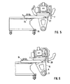
- the movement path show the FIGS. 6-8 ,
- the receiving means 10 pivots about the axis of rotation D, formed by the shaft 12.
- the carrier 7 approaches the linear displacement device 24 until it rests on it. This position is in Fig. 7 shown.
- the linear displacement device 24 is automatically pushed back onto the transport means 21 until the carrier 7 is completely released from the receiving means 10, after which the displacement device 24 is manually completely withdrawn.
- the carrier 7 together with the extrusion cylinder 4 and all supply lines etc. has thus been completely transferred from the receiving means 10 to the transport means 21.
- the linear displacement device 24 can now be moved back again, the transport 21 is removed. Subsequently, only the extrusion cylinder is to be moved into the Ankoppelwolf by driving the cylinder 18 and retracting against the extrusion direction. Now, the mechanical drive coupling is still to produce as well as the corresponding supply and control lines to connect, after which the operation can start immediately.
- the carrier side underside corresponding engaging projections 28 are provided, which engage respectively in the interventions 16 on both cheeks 14.
- the shape of the engagement projections 28 corresponds to the shape of the interventions 16, so that they can interlock positively. This is on the one hand, a fixation of the carrier 7, including construction on the receiving means 10 is realized, as well as the ability to automatically push back the linear displacement device 24 during the pivoting movement.
- a locking device 29 is shown, consisting of a dashed lines shown here, located on the machine frame pin 30 and provided on a part of the transmission 13 opening 31, which serves the bolt holder.
- the arrangement is such that the bolt 30 is guided in the bolt receptacle 31 until the receiving means 10 decouples the end position during the displacement movement controlled via the cylinder 18, which can be detected via a suitable limit switch. Only then can the pivoting be done, previously this is blocked due to the Bolzeneingriffs.
- the Figures 9 and 10 show the floating storage 32, over which the extrusion cylinder 4 is movably mounted with respect to the carrier 7.
- the extrusion cylinder is mounted at the front and rear end via two storage units.
- Each floating bearing 32 comprises a first plate 33 which is fixedly connected to the carrier 7, and a second plate 34 which carries the extrusion cylinder 4.
- Both plates 33, 34 are floating about not shown balls with respect to each other movable, that is, the extrusion cylinder 4 can be moved relative to the carrier 7.
- An alignment of the extrusion cylinder with respect to the drive unit for coupling is possible by way of this, likewise thermal expansion during operation can be compensated for here.
- each floating bearing 32 further comprises a pin 35 which can be moved via an actuating cylinder 36 up and down each.
- the pin 35 is extended. He passes through an opening 37, wherein the pin section located here in the opening has a smaller diameter than the opening, that is, the plate 34 is movable despite pin penetration. If the cylinder is to be handed over, it is necessary to lock it with respect to the carrier, for which purpose the pins 35 are pulled down over the adjusting cylinders 36.
- the upper end of the pin 35 has a diameter substantially equal to the diameter of the opening 37 adapted clamping portion 38 which is pulled into the opening 37, so that they no longer has a game.
- the opening 37 of the rear bearing unit in the extrusion direction is slotted, over which the stronger thermally induced elongations are absorbed there.
- Fig. 11 shows in the form of a schematic diagram of a further embodiment of a movement mechanism according to the invention for the receiving means.
- the receiving means 39 which is not shown here in detail, via a parallelogram linkage 40 about two separate axes 41, of which at least one is driven by a motor, pivotally, wherein the extrusion cylinder as Fig. 11 shows in this pivotal movement maintains its horizontal orientation.
- This in Fig. 11 shown transport means 42 may be formed according to the transport means 21 of the above-described embodiment and also have a linear displacement device 43, on which the carrier 44 of the extrusion cylinder is stored.
- the carrier 44 With regard to the mounting of the carrier 44 on the receiving means 39, corresponding sensors or locking members or the longitudinal displacement, etc., the above statements apply accordingly.
- Fig. 12 shows a further embodiment of a receiving means 45, which has a linear guide system 46 which allows a horizontal displacement of the extrusion cylinder.
- the transport means 48 also has a linear displacement device 49, but this is vertically movable via a lifting device 50.
- the carrier 47 including structure receives and then again is withdrawn, as shown in the end position shown on the right.
- the reception of a new extrusion cylinder takes place in the reverse sequence.
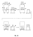
- Fig. 13 Finally shows a further embodiment of the invention, in which case the transport means 51 shows two receptacles 52 each formed by a linear displacement device 53 for each one mounted on a support extrusion cylinder.
- the receiving means 55 also here in the form of a linear guide system 56, positioned.
- the change of the carrier 57 from the linear guide system 56 to the linear displacement device 53 This is in the second part in Fig. 13 shown.
- the two receptacles 52 are moved vertically downwards via a central lifting device 58 until the upper receptacle 52 is aligned with respect to the receiving means 55.
- the pivoting version of the receiving means as shown in the Figures 1 - 8 is described, can be used.
Landscapes
- Engineering & Computer Science (AREA)
- Mechanical Engineering (AREA)
- Extrusion Moulding Of Plastics Or The Like (AREA)
Applications Claiming Priority (2)
| Application Number | Priority Date | Filing Date | Title |
|---|---|---|---|
| DE102004040186A DE102004040186B3 (de) | 2004-08-19 | 2004-08-19 | Einrichtung zum Wechseln eines Extrusionszylinders eines Extruders |
| EP05017472.1A EP1627723B1 (fr) | 2004-08-19 | 2005-08-11 | Dispositif pour échanger le cylindre à vis d'une extrudeuse |
Related Parent Applications (2)
| Application Number | Title | Priority Date | Filing Date |
|---|---|---|---|
| EP05017472.1 Division | 2005-08-11 | ||
| EP05017472.1A Division EP1627723B1 (fr) | 2004-08-19 | 2005-08-11 | Dispositif pour échanger le cylindre à vis d'une extrudeuse |
Publications (3)
| Publication Number | Publication Date |
|---|---|
| EP2251178A2 true EP2251178A2 (fr) | 2010-11-17 |
| EP2251178A3 EP2251178A3 (fr) | 2011-10-19 |
| EP2251178B1 EP2251178B1 (fr) | 2014-06-04 |
Family
ID=35457327
Family Applications (2)
| Application Number | Title | Priority Date | Filing Date |
|---|---|---|---|
| EP05017472.1A Expired - Lifetime EP1627723B1 (fr) | 2004-08-19 | 2005-08-11 | Dispositif pour échanger le cylindre à vis d'une extrudeuse |
| EP10004842.0A Expired - Lifetime EP2251178B1 (fr) | 2004-08-19 | 2005-08-11 | Dispositif pour échanger le cylindre à vis d'une extrudeuse |
Family Applications Before (1)
| Application Number | Title | Priority Date | Filing Date |
|---|---|---|---|
| EP05017472.1A Expired - Lifetime EP1627723B1 (fr) | 2004-08-19 | 2005-08-11 | Dispositif pour échanger le cylindre à vis d'une extrudeuse |
Country Status (4)
| Country | Link |
|---|---|
| US (1) | US7473087B2 (fr) |
| EP (2) | EP1627723B1 (fr) |
| JP (1) | JP4689405B2 (fr) |
| DE (1) | DE102004040186B3 (fr) |
Cited By (2)
| Publication number | Priority date | Publication date | Assignee | Title |
|---|---|---|---|---|
| EP4209128A1 (fr) | 2022-01-05 | 2023-07-12 | Gea Comas S.P.A. | Machine de dosage pour doser et/ou injecter des produits alimentaires |
| EP4209129A1 (fr) | 2022-01-05 | 2023-07-12 | Gea Comas S.P.A. | Machine de dosage pour doser et/ou injecter des produits alimentaires |
Families Citing this family (15)
| Publication number | Priority date | Publication date | Assignee | Title |
|---|---|---|---|---|
| EP1481785A1 (fr) * | 2003-05-28 | 2004-12-01 | Coperion Werner & Pfleiderer GmbH & Co. KG | Dispositif de traitement des matières liquides |
| DE102005043868B4 (de) | 2005-09-12 | 2013-10-17 | Zeppelin Reimelt Gmbh | Extrudergestell |
| JP4192170B2 (ja) * | 2005-09-13 | 2008-12-03 | 株式会社日本製鋼所 | 押出機およびそのシリンダ交換方法 |
| CA2607517C (fr) * | 2007-10-22 | 2012-01-31 | Manfred A. A. Lupke | Systeme d'extrusion de tuyauterie avec separation du noyau de refroidissement |
| US8137092B2 (en) * | 2008-05-22 | 2012-03-20 | Edward Williams | Support assembly for an extruder |
| CN101746036A (zh) * | 2008-12-09 | 2010-06-23 | 上海金发科技发展有限公司 | 一种更换塑料挤出机螺筒的装置 |
| DE102009014589B4 (de) * | 2009-03-24 | 2025-04-03 | Threetec Gmbh | Extrusionsvorrichtung zur Verarbeitung und/oder Aufbereitung von Zusammensetzungen |
| US8664819B2 (en) * | 2009-08-18 | 2014-03-04 | Northern Power Systems Utility Scale, Inc. | Method and apparatus for permanent magnet attachment in an electromechanical machine |
| US9515529B2 (en) | 2009-08-18 | 2016-12-06 | Northern Power Systems, Inc. | Method and apparatus for permanent magnet attachment in an electromechanical machine |
| US8113814B2 (en) * | 2009-09-18 | 2012-02-14 | Steer Engineering Private Limited | Barrel clamping system for quick assembling and dismantling of extruder barrel sections |
| DE102011114577A1 (de) | 2011-09-30 | 2013-04-04 | Thermo Electron (Karlsruhe) Gmbh | Extruder |
| ES2870129T3 (es) * | 2016-09-16 | 2021-10-26 | Haas Food Equipment Gmbh | Máquina de extrusión de masa alimenticia |
| US11161275B2 (en) * | 2019-03-27 | 2021-11-02 | Omachron Intellectual Property Inc. | Modular extruder |
| DE102020115250B4 (de) | 2019-09-12 | 2022-09-01 | Moritz Hülsmann | Extrusionsanlage |
| CN116100777B (zh) * | 2023-04-12 | 2023-06-09 | 河北聚丰华春保温材料有限公司 | 一种防腐管道成型用挤出设备 |
Family Cites Families (23)
| Publication number | Priority date | Publication date | Assignee | Title |
|---|---|---|---|---|
| US3408694A (en) * | 1966-08-25 | 1968-11-05 | Stewart Bolling & Co Inc | Extruder |
| US3619329A (en) * | 1969-02-28 | 1971-11-09 | Dow Chemical Co | Extrusion apparatus for the preparation of walled structures |
| US3712775A (en) * | 1971-04-16 | 1973-01-23 | Vistron Corp | Hopper loading extrusion apparatus |
| US3825387A (en) * | 1971-05-07 | 1974-07-23 | California Pellet Mill Co | Quick-change die and roller assembly |
| DE2654774C3 (de) * | 1976-12-03 | 1981-10-15 | Werner & Pfleiderer, 7000 Stuttgart | Schneckenmaschine zur Homogenisierung von aufgeschmolzenen Polymeren |
| DE2726963C3 (de) * | 1977-06-15 | 1980-04-30 | Hermann Berstorff Maschinenbau Gmbh, 3000 Hannover | Vorrichtung zum Abziehen eines Zylinderteiles von einem Schneckenextruder |
| JPS5819463B2 (ja) * | 1980-10-31 | 1983-04-18 | 菱屋精工株式会社 | 加熱シリンダ切替え型射出成形機 |
| JPS58102737A (ja) * | 1981-12-15 | 1983-06-18 | Toshiba Mach Co Ltd | 射出成形機における加熱シリンダユニツトの自動交換装置 |
| JPS58187323A (ja) * | 1982-04-28 | 1983-11-01 | Toshiba Mach Co Ltd | 射出装置 |
| DE3336179C2 (de) * | 1983-10-05 | 1986-11-20 | Hermann Berstorff Maschinenbau Gmbh, 3000 Hannover | Einrichtung zum Herstellen von aufgeschäumten thermoplastischen Kunststoffen |
| JPS60203400A (ja) * | 1984-03-26 | 1985-10-14 | Ikegai Corp | 二軸押出機 |
| DE3637569A1 (de) * | 1986-11-04 | 1988-05-11 | Battenfeld Kunststoffmasch | Wechselvorrichtung fuer den schneckenzylinder einer spritzgiessmaschine |
| JPH0140638Y2 (fr) * | 1987-01-23 | 1989-12-04 | ||
| US4750841A (en) * | 1987-08-27 | 1988-06-14 | Graham Engineering Corp. | Barrel support |
| JPH0344501Y2 (fr) * | 1988-04-14 | 1991-09-19 | ||
| DE8815075U1 (de) * | 1988-12-03 | 1990-04-05 | Manesty Machines Ltd., Liverpool, Lancashire | Tablettiermaschine |
| CN1037823C (zh) * | 1992-05-18 | 1998-03-25 | 加利福尼亚制片机公司 | 一种用于球团机的快速模具更换的定位装置 |
| PL172344B1 (pl) * | 1992-08-10 | 1997-09-30 | Friends Of Freesia Co | Urzadzenie do wytlaczania zywic plastycznych PL |
| JP2549803B2 (ja) * | 1992-11-17 | 1996-10-30 | 株式会社日本製鋼所 | スクリュ抜出方法及び装置 |
| JP2512677B2 (ja) * | 1993-02-16 | 1996-07-03 | アイ・ケー・ジー株式会社 | 押出機のシリンダ装置 |
| JPH06262665A (ja) | 1993-03-16 | 1994-09-20 | Daicel Chem Ind Ltd | 押出機の交換方法 |
| AT403025B (de) * | 1994-04-08 | 1997-10-27 | Unitek Maschnb & Handel Gmbh | Wechseleinrichtung von spritzköpfen |
| JP2001150509A (ja) * | 1999-11-29 | 2001-06-05 | Toshiba Mach Co Ltd | 押出機 |
-
2004
- 2004-08-19 DE DE102004040186A patent/DE102004040186B3/de not_active Expired - Fee Related
-
2005
- 2005-08-11 EP EP05017472.1A patent/EP1627723B1/fr not_active Expired - Lifetime
- 2005-08-11 EP EP10004842.0A patent/EP2251178B1/fr not_active Expired - Lifetime
- 2005-08-17 US US11/206,941 patent/US7473087B2/en not_active Expired - Fee Related
- 2005-08-18 JP JP2005237092A patent/JP4689405B2/ja not_active Expired - Fee Related
Non-Patent Citations (1)
| Title |
|---|
| None |
Cited By (2)
| Publication number | Priority date | Publication date | Assignee | Title |
|---|---|---|---|---|
| EP4209128A1 (fr) | 2022-01-05 | 2023-07-12 | Gea Comas S.P.A. | Machine de dosage pour doser et/ou injecter des produits alimentaires |
| EP4209129A1 (fr) | 2022-01-05 | 2023-07-12 | Gea Comas S.P.A. | Machine de dosage pour doser et/ou injecter des produits alimentaires |
Also Published As
| Publication number | Publication date |
|---|---|
| EP2251178B1 (fr) | 2014-06-04 |
| JP2006056258A (ja) | 2006-03-02 |
| US7473087B2 (en) | 2009-01-06 |
| EP1627723A3 (fr) | 2007-11-07 |
| EP1627723B1 (fr) | 2013-12-18 |
| JP4689405B2 (ja) | 2011-05-25 |
| EP2251178A3 (fr) | 2011-10-19 |
| US20060040010A1 (en) | 2006-02-23 |
| EP1627723A2 (fr) | 2006-02-22 |
| DE102004040186B3 (de) | 2006-04-27 |
Similar Documents
| Publication | Publication Date | Title |
|---|---|---|
| EP2251178B1 (fr) | Dispositif pour échanger le cylindre à vis d'une extrudeuse | |
| EP1882580B1 (fr) | Conteneur interchangeable | |
| EP2387487B1 (fr) | Système de robot pour poser une file de rails | |
| EP0069221B1 (fr) | Installation mécanique avec au moins une machine au coulage par injection et dispositif pour un remplacement de l'unité d'outil et de l'unité de moulage de la machine | |
| DE3326067A1 (de) | Formwechselvorrichtung | |
| EP1407873B1 (fr) | Dispositif pour produire des tuyaux ondulés | |
| EP2746021A1 (fr) | Procédé et dispositif de fabrication de pièces moulées | |
| DE102011112801B4 (de) | Spritzgussmaschine mit Flachbauetagenwerkzeugträger | |
| EP2281761B1 (fr) | Dispositif de transport de bande | |
| EP0901848B1 (fr) | Presse de transfert avec changement d' outil automatique | |
| DE3501000A1 (de) | Werkzeug-einbau- und spannvorrichtung an einer spritzgiessmaschine | |
| EP0792719A1 (fr) | Centre d'usinage | |
| DE3617094C2 (fr) | ||
| EP1238780B1 (fr) | Procédé et dispositif pour la fabrication de tuyaux transversalement ondulés en matière thermoplastique | |
| EP0607541A1 (fr) | Calandre et installation de calandrage | |
| DE19615798A1 (de) | Vorrichtung zum Herstellen von Hohlkörpern aus thermoplastischem Kunststoff mittels Extrusions-Blasformen | |
| EP2439046B1 (fr) | Système de fermeture d'outil pour machines de soufflage en matière synthétique | |
| DE19919433A1 (de) | Orientierstation mit Stabgetriebe | |
| WO2006045284A1 (fr) | Dispositif de changement d'outillage automatique | |
| DE4035004A1 (de) | Saugerspinnenwechseleinrichtung zum automatischen umruesten von zufuehr- bzw. entnahmeeinrichtungen fuer grossflaechige blechteile | |
| EP1563926B1 (fr) | Dispositif et procédé de transport de pièces à usiner | |
| DE102006026608A1 (de) | Säulenziehvorrichtung | |
| EP4640397A1 (fr) | Appareil de lissage | |
| EP1572437A1 (fr) | Thermocolleuse a element chauffant et procede pour changer rapidement des outils sur des thermocolleuses a element chauffant | |
| DE19950201A1 (de) | Abtropfstation und Verfahren zum Entfernen eines Nassmediums aus Fahrzeugkarosserien |
Legal Events
| Date | Code | Title | Description |
|---|---|---|---|
| PUAI | Public reference made under article 153(3) epc to a published international application that has entered the european phase |
Free format text: ORIGINAL CODE: 0009012 |
|
| AC | Divisional application: reference to earlier application |
Ref document number: 1627723 Country of ref document: EP Kind code of ref document: P |
|
| AK | Designated contracting states |
Kind code of ref document: A2 Designated state(s): AT BE BG CH CY CZ DE DK EE ES FI FR GB GR HU IE IS IT LI LT LU LV MC NL PL PT RO SE SI SK TR |
|
| AX | Request for extension of the european patent |
Extension state: AL BA HR MK YU |
|
| RAP1 | Party data changed (applicant data changed or rights of an application transferred) |
Owner name: LEISTRITZ EXTRUSIONSTECHNIK GMBH |
|
| PUAL | Search report despatched |
Free format text: ORIGINAL CODE: 0009013 |
|
| AK | Designated contracting states |
Kind code of ref document: A3 Designated state(s): AT BE BG CH CY CZ DE DK EE ES FI FR GB GR HU IE IS IT LI LT LU LV MC NL PL PT RO SE SI SK TR |
|
| AX | Request for extension of the european patent |
Extension state: AL BA HR MK YU |
|
| RIC1 | Information provided on ipc code assigned before grant |
Ipc: B29C 47/08 20060101AFI20110909BHEP |
|
| 17P | Request for examination filed |
Effective date: 20120111 |
|
| 17Q | First examination report despatched |
Effective date: 20130822 |
|
| RIC1 | Information provided on ipc code assigned before grant |
Ipc: B29C 47/08 20060101AFI20131212BHEP Ipc: B29C 47/66 20060101ALI20131212BHEP |
|
| GRAP | Despatch of communication of intention to grant a patent |
Free format text: ORIGINAL CODE: EPIDOSNIGR1 |
|
| INTG | Intention to grant announced |
Effective date: 20140303 |
|
| GRAS | Grant fee paid |
Free format text: ORIGINAL CODE: EPIDOSNIGR3 |
|
| GRAA | (expected) grant |
Free format text: ORIGINAL CODE: 0009210 |
|
| AC | Divisional application: reference to earlier application |
Ref document number: 1627723 Country of ref document: EP Kind code of ref document: P |
|
| AK | Designated contracting states |
Kind code of ref document: B1 Designated state(s): AT BE BG CH CY CZ DE DK EE ES FI FR GB GR HU IE IS IT LI LT LU LV MC NL PL PT RO SE SI SK TR |
|
| REG | Reference to a national code |
Ref country code: GB Ref legal event code: FG4D Free format text: NOT ENGLISH |
|
| REG | Reference to a national code |
Ref country code: CH Ref legal event code: EP |
|
| REG | Reference to a national code |
Ref country code: AT Ref legal event code: REF Ref document number: 670814 Country of ref document: AT Kind code of ref document: T Effective date: 20140615 |
|
| REG | Reference to a national code |
Ref country code: IE Ref legal event code: FG4D Free format text: LANGUAGE OF EP DOCUMENT: GERMAN |
|
| REG | Reference to a national code |
Ref country code: DE Ref legal event code: R096 Ref document number: 502005014386 Country of ref document: DE Effective date: 20140717 |
|
| REG | Reference to a national code |
Ref country code: NL Ref legal event code: VDEP Effective date: 20140604 |
|
| PG25 | Lapsed in a contracting state [announced via postgrant information from national office to epo] |
Ref country code: GR Free format text: LAPSE BECAUSE OF FAILURE TO SUBMIT A TRANSLATION OF THE DESCRIPTION OR TO PAY THE FEE WITHIN THE PRESCRIBED TIME-LIMIT Effective date: 20140905 Ref country code: CY Free format text: LAPSE BECAUSE OF FAILURE TO SUBMIT A TRANSLATION OF THE DESCRIPTION OR TO PAY THE FEE WITHIN THE PRESCRIBED TIME-LIMIT Effective date: 20140604 Ref country code: LT Free format text: LAPSE BECAUSE OF FAILURE TO SUBMIT A TRANSLATION OF THE DESCRIPTION OR TO PAY THE FEE WITHIN THE PRESCRIBED TIME-LIMIT Effective date: 20140604 Ref country code: FI Free format text: LAPSE BECAUSE OF FAILURE TO SUBMIT A TRANSLATION OF THE DESCRIPTION OR TO PAY THE FEE WITHIN THE PRESCRIBED TIME-LIMIT Effective date: 20140604 |
|
| PGFP | Annual fee paid to national office [announced via postgrant information from national office to epo] |
Ref country code: DE Payment date: 20140818 Year of fee payment: 10 Ref country code: CH Payment date: 20140821 Year of fee payment: 10 |
|
| REG | Reference to a national code |
Ref country code: LT Ref legal event code: MG4D |
|
| PG25 | Lapsed in a contracting state [announced via postgrant information from national office to epo] |
Ref country code: SE Free format text: LAPSE BECAUSE OF FAILURE TO SUBMIT A TRANSLATION OF THE DESCRIPTION OR TO PAY THE FEE WITHIN THE PRESCRIBED TIME-LIMIT Effective date: 20140604 Ref country code: LV Free format text: LAPSE BECAUSE OF FAILURE TO SUBMIT A TRANSLATION OF THE DESCRIPTION OR TO PAY THE FEE WITHIN THE PRESCRIBED TIME-LIMIT Effective date: 20140604 |
|
| PGFP | Annual fee paid to national office [announced via postgrant information from national office to epo] |
Ref country code: AT Payment date: 20140820 Year of fee payment: 10 Ref country code: FR Payment date: 20140819 Year of fee payment: 10 |
|
| PGFP | Annual fee paid to national office [announced via postgrant information from national office to epo] |
Ref country code: IT Payment date: 20140825 Year of fee payment: 10 |
|
| PG25 | Lapsed in a contracting state [announced via postgrant information from national office to epo] |
Ref country code: SK Free format text: LAPSE BECAUSE OF FAILURE TO SUBMIT A TRANSLATION OF THE DESCRIPTION OR TO PAY THE FEE WITHIN THE PRESCRIBED TIME-LIMIT Effective date: 20140604 Ref country code: RO Free format text: LAPSE BECAUSE OF FAILURE TO SUBMIT A TRANSLATION OF THE DESCRIPTION OR TO PAY THE FEE WITHIN THE PRESCRIBED TIME-LIMIT Effective date: 20140604 Ref country code: ES Free format text: LAPSE BECAUSE OF FAILURE TO SUBMIT A TRANSLATION OF THE DESCRIPTION OR TO PAY THE FEE WITHIN THE PRESCRIBED TIME-LIMIT Effective date: 20140604 Ref country code: CZ Free format text: LAPSE BECAUSE OF FAILURE TO SUBMIT A TRANSLATION OF THE DESCRIPTION OR TO PAY THE FEE WITHIN THE PRESCRIBED TIME-LIMIT Effective date: 20140604 Ref country code: PT Free format text: LAPSE BECAUSE OF FAILURE TO SUBMIT A TRANSLATION OF THE DESCRIPTION OR TO PAY THE FEE WITHIN THE PRESCRIBED TIME-LIMIT Effective date: 20141006 Ref country code: EE Free format text: LAPSE BECAUSE OF FAILURE TO SUBMIT A TRANSLATION OF THE DESCRIPTION OR TO PAY THE FEE WITHIN THE PRESCRIBED TIME-LIMIT Effective date: 20140604 |
|
| PG25 | Lapsed in a contracting state [announced via postgrant information from national office to epo] |
Ref country code: IS Free format text: LAPSE BECAUSE OF FAILURE TO SUBMIT A TRANSLATION OF THE DESCRIPTION OR TO PAY THE FEE WITHIN THE PRESCRIBED TIME-LIMIT Effective date: 20141004 Ref country code: PL Free format text: LAPSE BECAUSE OF FAILURE TO SUBMIT A TRANSLATION OF THE DESCRIPTION OR TO PAY THE FEE WITHIN THE PRESCRIBED TIME-LIMIT Effective date: 20140604 Ref country code: NL Free format text: LAPSE BECAUSE OF FAILURE TO SUBMIT A TRANSLATION OF THE DESCRIPTION OR TO PAY THE FEE WITHIN THE PRESCRIBED TIME-LIMIT Effective date: 20140604 |
|
| REG | Reference to a national code |
Ref country code: DE Ref legal event code: R097 Ref document number: 502005014386 Country of ref document: DE |
|
| PG25 | Lapsed in a contracting state [announced via postgrant information from national office to epo] |
Ref country code: MC Free format text: LAPSE BECAUSE OF FAILURE TO SUBMIT A TRANSLATION OF THE DESCRIPTION OR TO PAY THE FEE WITHIN THE PRESCRIBED TIME-LIMIT Effective date: 20140604 Ref country code: LU Free format text: LAPSE BECAUSE OF FAILURE TO SUBMIT A TRANSLATION OF THE DESCRIPTION OR TO PAY THE FEE WITHIN THE PRESCRIBED TIME-LIMIT Effective date: 20140811 |
|
| PLBE | No opposition filed within time limit |
Free format text: ORIGINAL CODE: 0009261 |
|
| STAA | Information on the status of an ep patent application or granted ep patent |
Free format text: STATUS: NO OPPOSITION FILED WITHIN TIME LIMIT |
|
| PG25 | Lapsed in a contracting state [announced via postgrant information from national office to epo] |
Ref country code: DK Free format text: LAPSE BECAUSE OF FAILURE TO SUBMIT A TRANSLATION OF THE DESCRIPTION OR TO PAY THE FEE WITHIN THE PRESCRIBED TIME-LIMIT Effective date: 20140604 Ref country code: BE Free format text: LAPSE BECAUSE OF NON-PAYMENT OF DUE FEES Effective date: 20140831 |
|
| 26N | No opposition filed |
Effective date: 20150305 |
|
| REG | Reference to a national code |
Ref country code: IE Ref legal event code: MM4A |
|
| GBPC | Gb: european patent ceased through non-payment of renewal fee |
Effective date: 20140904 |
|
| REG | Reference to a national code |
Ref country code: DE Ref legal event code: R097 Ref document number: 502005014386 Country of ref document: DE Effective date: 20150305 |
|
| PG25 | Lapsed in a contracting state [announced via postgrant information from national office to epo] |
Ref country code: SI Free format text: LAPSE BECAUSE OF FAILURE TO SUBMIT A TRANSLATION OF THE DESCRIPTION OR TO PAY THE FEE WITHIN THE PRESCRIBED TIME-LIMIT Effective date: 20140604 Ref country code: GB Free format text: LAPSE BECAUSE OF NON-PAYMENT OF DUE FEES Effective date: 20140904 |
|
| PG25 | Lapsed in a contracting state [announced via postgrant information from national office to epo] |
Ref country code: IE Free format text: LAPSE BECAUSE OF NON-PAYMENT OF DUE FEES Effective date: 20140811 |
|
| REG | Reference to a national code |
Ref country code: DE Ref legal event code: R119 Ref document number: 502005014386 Country of ref document: DE |
|
| REG | Reference to a national code |
Ref country code: CH Ref legal event code: PL |
|
| REG | Reference to a national code |
Ref country code: AT Ref legal event code: MM01 Ref document number: 670814 Country of ref document: AT Kind code of ref document: T Effective date: 20150811 |
|
| PG25 | Lapsed in a contracting state [announced via postgrant information from national office to epo] |
Ref country code: LI Free format text: LAPSE BECAUSE OF NON-PAYMENT OF DUE FEES Effective date: 20150831 Ref country code: CH Free format text: LAPSE BECAUSE OF NON-PAYMENT OF DUE FEES Effective date: 20150831 Ref country code: IT Free format text: LAPSE BECAUSE OF NON-PAYMENT OF DUE FEES Effective date: 20150811 |
|
| PG25 | Lapsed in a contracting state [announced via postgrant information from national office to epo] |
Ref country code: BG Free format text: LAPSE BECAUSE OF FAILURE TO SUBMIT A TRANSLATION OF THE DESCRIPTION OR TO PAY THE FEE WITHIN THE PRESCRIBED TIME-LIMIT Effective date: 20140604 Ref country code: AT Free format text: LAPSE BECAUSE OF NON-PAYMENT OF DUE FEES Effective date: 20150811 |
|
| REG | Reference to a national code |
Ref country code: FR Ref legal event code: ST Effective date: 20160429 |
|
| PG25 | Lapsed in a contracting state [announced via postgrant information from national office to epo] |
Ref country code: DE Free format text: LAPSE BECAUSE OF NON-PAYMENT OF DUE FEES Effective date: 20160301 Ref country code: HU Free format text: LAPSE BECAUSE OF FAILURE TO SUBMIT A TRANSLATION OF THE DESCRIPTION OR TO PAY THE FEE WITHIN THE PRESCRIBED TIME-LIMIT; INVALID AB INITIO Effective date: 20050811 Ref country code: TR Free format text: LAPSE BECAUSE OF FAILURE TO SUBMIT A TRANSLATION OF THE DESCRIPTION OR TO PAY THE FEE WITHIN THE PRESCRIBED TIME-LIMIT Effective date: 20140604 |
|
| PG25 | Lapsed in a contracting state [announced via postgrant information from national office to epo] |
Ref country code: FR Free format text: LAPSE BECAUSE OF NON-PAYMENT OF DUE FEES Effective date: 20150831 |