EP2251477A1 - Machine à laver - Google Patents
Machine à laver Download PDFInfo
- Publication number
- EP2251477A1 EP2251477A1 EP09006394A EP09006394A EP2251477A1 EP 2251477 A1 EP2251477 A1 EP 2251477A1 EP 09006394 A EP09006394 A EP 09006394A EP 09006394 A EP09006394 A EP 09006394A EP 2251477 A1 EP2251477 A1 EP 2251477A1
- Authority
- EP
- European Patent Office
- Prior art keywords
- drum
- opening
- washing machine
- tub
- housing
- Prior art date
- Legal status (The legal status is an assumption and is not a legal conclusion. Google has not performed a legal analysis and makes no representation as to the accuracy of the status listed.)
- Granted
Links
- 238000005406 washing Methods 0.000 title claims abstract description 106
- 238000003756 stirring Methods 0.000 claims description 3
- 238000004140 cleaning Methods 0.000 description 10
- XLYOFNOQVPJJNP-UHFFFAOYSA-N water Substances O XLYOFNOQVPJJNP-UHFFFAOYSA-N 0.000 description 9
- 239000007788 liquid Substances 0.000 description 7
- 238000010276 construction Methods 0.000 description 5
- 238000007689 inspection Methods 0.000 description 3
- 230000004048 modification Effects 0.000 description 3
- 238000012986 modification Methods 0.000 description 3
- 230000009471 action Effects 0.000 description 2
- 238000001035 drying Methods 0.000 description 2
- 238000001914 filtration Methods 0.000 description 2
- 238000001514 detection method Methods 0.000 description 1
- 238000007599 discharging Methods 0.000 description 1
- 230000005484 gravity Effects 0.000 description 1
- 239000000463 material Substances 0.000 description 1
- 230000007246 mechanism Effects 0.000 description 1
- 238000000465 moulding Methods 0.000 description 1
- 239000002245 particle Substances 0.000 description 1
- 239000008237 rinsing water Substances 0.000 description 1
- 238000011144 upstream manufacturing Methods 0.000 description 1
- 238000009736 wetting Methods 0.000 description 1
Images




Classifications
-
- D—TEXTILES; PAPER
- D06—TREATMENT OF TEXTILES OR THE LIKE; LAUNDERING; FLEXIBLE MATERIALS NOT OTHERWISE PROVIDED FOR
- D06F—LAUNDERING, DRYING, IRONING, PRESSING OR FOLDING TEXTILE ARTICLES
- D06F39/00—Details of washing machines not specific to a single type of machines covered by groups D06F9/00 - D06F27/00
- D06F39/10—Filtering arrangements
-
- D—TEXTILES; PAPER
- D06—TREATMENT OF TEXTILES OR THE LIKE; LAUNDERING; FLEXIBLE MATERIALS NOT OTHERWISE PROVIDED FOR
- D06F—LAUNDERING, DRYING, IRONING, PRESSING OR FOLDING TEXTILE ARTICLES
- D06F37/00—Details specific to washing machines covered by groups D06F21/00 - D06F25/00
- D06F37/02—Rotary receptacles, e.g. drums
- D06F37/04—Rotary receptacles, e.g. drums adapted for rotation or oscillation about a horizontal or inclined axis
- D06F37/06—Ribs, lifters, or rubbing means forming part of the receptacle
Definitions
- the present invention refers to a washing machine
- washing machines both “simple” washing machines (i.e. washing machines which can only wash and rinse the laundry) and washing-drying machines (i.e. washing machines which can also dry the laundry), usually comprise an external casing provided with a loading/unloading door which allows the access to a washing tub containing a rotary perforated drum in which the laundry to be washed can be loaded.
- the drum is provided with some lifters adapted to improve the stirring of the laundry during the rotation of the drum; the lifters are substantially prismatic elements fixed to the inner lateral surface of the drum and positioned with their longitudinal axis substantially parallel to the longitudinal axis of the drum.
- first type of known washing machines called “front-loading” washing machines
- front-loading washing machines on the frontal wall of the external casing it is obtained a first opening, adapted for allowing the loading/unloading of the laundry, facing a second opening obtained in the tub and a third opening obtained in one base of the drum; the borders of these first and second openings are connected by a flexible bellows.
- the first opening is closable by a porthole hinged to the frontal wall of the external casing.
- top-loading washing machines on the upper surface of the external casing it is obtained a substantially rectangular first opening, facing a corresponding second opening obtained in the lateral surface of the tub; also in this case the borders of the first and second openings are connected by a flexible bellows.
- the first opening is closable by an external lid hinged to the upper surface of the external casing.
- a third opening is obtained, adapted, when it is positioned in correspondence to the first and to the second openings, to allow the loading/unloading of the laundry in the drum.
- the third opening is closable by one or, most frequently, by two internal lids, which, when closed, substantially constitute a portion of the cylindrical lateral surface of the drum; these internal lids, when opened and placed in the loading position, engage the border of the first opening obtained in the external casing, partially exiting from the latter, and limiting in this way the rotation of the rotary drum during the opening of the latter.
- Both the above mentioned front-loading and top-loading washing machines comprise a water outlet circuit, typically comprising a drain pump and some draining pipes, adapted to drain water from the tub after the washing and rinsing phases.
- the water outlet circuit usually comprises filtering means, placed between the bottom of the tub and the drain pump, adapted to retain all undesirable bodies (for example buttons came off from the laundry, coins erroneously introduced into the washing machine, etc.) passed through the holes located on the periphery of the drum, or fell to the bottom of the tub by passing between the drum and the tub, which could damage or obstruct the pump.
- filtering means placed between the bottom of the tub and the drain pump, adapted to retain all undesirable bodies (for example buttons came off from the laundry, coins erroneously introduced into the washing machine, etc.) passed through the holes located on the periphery of the drum, or fell to the bottom of the tub by passing between the drum and the tub, which could damage or obstruct the pump.
- the most common of these filtering means consists of a cylindrical box attached to the base of the washing machine and containing a removable filter fluidly connected upstream of the drain pump.
- This box containing the filter is accessible through a quick-removable plug that allows the filter to be removed and cleaned, the plug being hidden by a gate located, depending on the case, on the front or back wall of the external casing of the washing machine.
- washing machines of the top-loading type comprising a draining sump obtained on the lower region of the lateral surface of the tub, and fluidly communicating with the internal of the latter; a filter is placed in a housing obtained inside the draining sump, and the drain pump is attached to the tub in the extension of this draining sump.
- one of the above mentioned lifters arranged longitudinally to the drum and protruding internally to the latter, is removable, in order to allow the access to the underlying housing, and the removal/ repositioning of the filter, for example for its cleaning.
- a prior art washing machine containing a filter used to prevent residual particles of dirt from reaching and obstructing the pump and its drainage duct, and which can be removed from the internal of the tub, for inspection, cleaning and replacement, is illustrated, for example, in GB 1197919 , which discloses a washing machine comprising a tank (i.e. a tub) for liquid with an opening in its base, a draining pump connected by a pipe to the opening of the tank, and a basket (i.e. a rotary drum) disposed within the tank; a cup-like filter element having filter openings in its side wall is removably seated in the tank opening, and an opening is provided in the basket, provided with a removable closure, to provide access to the filter element.
- a tank i.e. a tub
- a draining pump connected by a pipe to the opening of the tank
- a basket i.e. a rotary drum
- FR 2190966 discloses a top-loading washing machine comprising a tub containing a rotary drum provided, on its lateral surface, with a first door, adapted for loading/unloading the laundry, and with a second door, disposed opposite to the first door and adapted for allowing the recovering of linen which would have slipped between the tank and the drum.
- a connector is fixed to the bottom of the tub, such connector being provided, at his inferior region, with a duct adapted to receive one of the extremities of a discharging pipe.
- a housing is provided in the connector, adapted to receive a filter accessible by simultaneously opening the two doors of the drum.
- EP 1 849 904 discloses a top-loading washing machine comprising a draining filter access apparatus integrated in a lifter diametrically opposite to the drum access door (i.e. to the internal lid allowing the access to the drum).
- the draining filter access apparatus comprises a body, including an opening aligned with an opening of the same shape and dimensions made in the body of the drum, and a lid, hinged to the body and locking on the body by a simple ratchet mechanism.
- the rotation allowed to the rotary drum is limited by the engagement of the internal lids with the border of the opening obtained in the external casing; the position of the opening lifter with respect to the drum is set in such a way that, when the washing machine is in the loading position, the opening lifter is placed approximately above the filter housing, in a position that allows placing the opening lifter above the filter housing by at most a small rotation of the drum. In this way, when the inner lids are in the loading position, the user has to apply at most a small rotation to the drum in order to align the latter with the tub, thus allowing the access to the housing of the filter.
- the drum can freely rotate with respect to the tub even if the porthole is opened, and therefore the setting of the angular position of the drum in which the opening lifter is aligned with the underlying filter housing, necessary both when the filter has to be removed and when the filter has to be repositioned after cleaning, is more complicated and time expensive with respect to the top-loading solution.
- the drum can be rotated even during the removal and during the repositioning of the filter, with the consequent risk of injuring the user, and/or of breaking the filter.
- the aim of the present invention is therefore to obtain a washing machine which facilitates the access to the filter, so as, for example, to facilitate and to speed up the removing/repositioning of such a filter from/to the housing associated to the tub, and/or the cleaning and/or the inspection of such a filter.
- Another object of the invention is to obtain a washing machine which facilitates the reaching of the angular-positioning of the drum allowing the access to the filter.
- Another object of the invention is to obtain a washing machine which allows a safe removing/repositioning and/or clening and/or inspecting of the filter.
- the Applicant has found that by the use of locking means adapted to lock the rotation of the drum of a washing machine with respect to the tub, when an opening, obtained in a lateral surface of the drum, faces a housing for a filter adapted to impede the passage of bodies of fixed dimensions from the tub to a draining circuit, and/or by the use of locking means adapted to impede the opening of a closing device adapted for selectively closing the opening when the opening doesn't face the housing, and to allow the opening of the closing device when the opening faces the housing, it is possible to have an easy and fast access to the filter, for example for its removal/repositioning from/to the housing and/or for its cleaning and/or inspecting.
- a washing machine comprising:
- the washing machine 1 according to the invention which is illustrated in the enclosed Figures is advantageously of the front-loading type; even if from the following description it will be clear that the advantages of the invention can be particularly appreciated in the case of a front-loading washing machine, the invention is however applicable, substantially without any substantial modification, to a top-loading washing machine.
- the invention can be applied, substantially without any substantial modification, both to a "simple" washing machine (i.e. a washing machine which can only wash and rinse the laundry) and to a washing-drying machine (i.e. a washing machine which can also dry the laundry).
- a "simple" washing machine i.e. a washing machine which can only wash and rinse the laundry
- a washing-drying machine i.e. a washing machine which can also dry the laundry.
- the washing machine 1 according to the invention, schematically represented in Figure 1 , comprises an external casing 2 in which frontal wall 2a an access opening 3 is obtained, provided with a loading/unloading door 4, which allows the access to a washing tub 5, contained in the external casing 2; the washing tub 5 contains a rotary perforated drum 6 in which the laundry to be washed, not illustrated, can be loaded (in the enclosed Figures, the holes obtained in the lateral surface of the rotary perforated drum 6 have not been represented).
- the tub 5 is connected the external casing 2 via a flexible bellows 7, connected between the frontal, opened, surface of the tub 5 facing the access opening 3, and the border of the latter.
- the washing machine 1 comprises a water inlet circuit 8 adapted to feed water and washing/rinsing products into the tub 5; the water inlet circuit of a washing machine is well known in the art, and therefore will not be described in detail.
- the washing machine 1 comprises a draining sump 9, obtained preferably on the lateral surface 5a of the tub 5, fluidly communicating with the internal of the tub 5, and fluidly connected to a draining circuit 10 adapted to drain the washing/rinsing liquid (i.e. water and water mixed with washing and/or rinsing products) from the tub 5.
- the draining circuit 10 comprises a draining pump, not illustrated, and one or more draining pipes, adapted to drain water from the tub after the washing and rinsing phases; the draining circuit of a washing machine is well known in the art, and therefore will not be described in detail.
- the draining circuit 10 can be also provided with a recirculation circuit, adapted to drain the washing/rinsing liquid from the bottom of the tub 5, and to re-admit such liquid into an upper region of the tub, for improving the wetting of the laundry.
- a recirculation circuit adapted to drain the washing/rinsing liquid from the bottom of the tub 5, and to re-admit such liquid into an upper region of the tub, for improving the wetting of the laundry.
- the recirculation circuit of a washing machine is well known in the art, and therefore will not be described in detail.
- draining sump 9 is placed in the lower region of the tub 5, so that the liquid contained in the latter can be conveyed by gravity towards this draining sump 9, and therefore to the draining circuit 10.
- the draining sump 9 is obtained in a single-piece construction with the lower region of the tub 5, advantageously by moulding of a plastic material.
- the draining pump of the draining circuit 10 comprises an impeller, not illustrated, housed in a body obtained in a single-piece construction with the tub 5 and/or with the sump 9.
- the draining sump 9 is provided with a housing 11 for a filter 12 adapted to impede the passage of bodies of fixed dimensions from the tub 5 to the draining circuit 10 (and therefore to the pump of the latter).
- bodies can be, for example, buttons came off from the laundry, coins or other little objects contained in the pockets of trousers or other clothes and erroneously introduced into the washing machine 1, etc.
- the filter 12 can be extractable from the housing 11, as in the embodiments illustrated in the enclosed figures, or alternatively, in another embodiment, not illustrated, the filter 12 can be fixed to the housing 11 or obtained in a single-piece construction with the latter.
- the filter 12 is substantially box-shaped and is provided, on its lateral surface, with a plurality of holes 13 (or apertures) adapted to allow the passage of liquids, but to avoid the passage of objects (e.g. coins or buttons) whose dimensions are higher than a prefixed value depending on the dimensions of the holes 13.
- objects e.g. coins or buttons
- the filter 12 is arranged in such a way that, when it is positioned into the housing 11, all the liquids entering the draining sump 9 have to pass through this filter 12 before going to the draining circuit 10; in this way bodies like buttons, coins, etc, contained in the washing or rinsing water, are trapped in the filter 12, and don't reach the draining circuit 10.
- the filter 12 can be removed from the housing 11, for example for its cleaning, and it can be afterwards repositioned in the housing 11.
- the filter 12 is fixed to the housing 11 in a permanent way, or it is a single-piece construction with the housing 11, and therefore it can't be removed from the housing 11; in this case a user can perform the cleaning of the filter 12 directly in the housing 11. It is clear that in the case in which the filter 12 is a single-piece construction with the housing 11, the filter and the housing partially or totally coincide.
- the drum 6 is provided, on its lateral surface 6a, with an opening 14, adapted for allowing the access to the housing 11 of the draining sump 9, so as to allow acceding to the filter 12, for example for removing/repositioning and/or cleaning and/or inspecting the latter, when the drum 6 is positioned in such a way that this opening 14 faces the housing 11.
- the washing machine 1 also comprises a closing device 15 adapted for selectively closing the opening 14.
- the closing device 15 comprises a closing element, preferably a lifter 16, pivoted on a suitable frame 17 fixed to the lateral surface 6a of the drum 6 in proximity to the edge of the opening 14.
- the frame 17 isn't present, and the lifter 16 is pivoted directly on the lateral surface 6a of the drum 6.
- the lifter 16 is arranged in such a way that it can be positioned in a closed position, illustrated for example in Figure 2 , in which it closes the opening 14, or in an opened position, illustrated for example in Figure 3 , in which it is lifted from the opening 14.
- the lifter 16 operates as a traditional lifter, and is therefore useful for improving the stirring of the laundry during the rotation of the drum 6.
- the closing element of the closing device 15 is a lifter 16
- the closing device 15 could comprise, instead of a lifter 16, another suitable closing element (for example a lid or a porthole) adapted to selectively close the opening 14.
- the closing element could be pivoted on the lateral surface 6a of the drum 6, or to a frame 17 fixed to the latter (as in the embodiments illustrated in the enclosed Figures); in another embodiment, not illustrated, the closing element could also be slidably associated to the drum, or it can be associated to the drum in a completely removable way.
- a lifter 16 can be referred, substantially without modifications, to another suitable closing element (for example a lid, a porthole, etc.).
- the lifter 16 illustrated in the enclosed Figures is a box-shaped body, with a substantially triangular or trapezoidal or semicircular cross section, and it is positioned with its longitudinal axis substantially parallel to a longitudinal axis 18 of the drum 6; preferably the lifter 16 is pivoted on the frame 17 in proximity of its end placed near to the rear end 6b of the drum 6, opposite to the access opening 3 of the washing machine 1.
- the lifter 16 can be pivoted in correspondence to its end placed near to the access opening 3, or it can be also pivoted in correspondence to one of its longitudinal sides.
- the washing machine 1 comprises locking means adapted to selectively lock the rotation of the drum 6 with respect to the tub 5 when the opening 14 faces the housing 11, and/or locking means adapted to impede the opening of the closing device 15 when the opening 14 doesn't face the housing 11 and to allow the opening of the closing device 15 when the opening 14 faces the housing 11.
- the locking means advantageously comprise a seat 19, provided in/at the tub 5, adapted to engage a movable body (which will be better described in the following), adapted in turn to interact with the drum 6, so as to lock the rotation of the latter with respect to the tub 5 when the opening 14 of the drum 6 faces the housing 11.
- the movable body could be associated or associable to the drum 6 and/or to the closing device 15.
- the seat 19 and the movable body are arranged in such a way that the latter can be lodged in the seat 19 only when the opening 14 provided in the lateral surface 6a of the drum 6 faces the housing 11 provided in the tub 5, so that the drum 6 can be locked with respect to the tub 5 only in this position.
- the movable body advantageously comprises a pin 20, associated or associable to the drum 6, as will be better explained in the following.
- the pin 20 is associated or associable to (or in proximity to) the closing device 15, but it is clear that the pin 20 should be associated substantially to any region of the drum 6; in any case the seat 19 provided in/at the tub 5 must be arranged in such a way that the pin 20 can be lodged in (or can engage) the seat 19 only when the opening 14 of the drum 6 faces the housing 11 of the tub 5.
- the seat 19 could be obtained directly in the tub 5, as illustrated for example in Figures 4 and 5 , or in a further element associated to the tub 5, for example in a further frame 19a, as illustrated for example in Figures 8 , 12 and 16 , or in a protrusion, etc.
- the seat 19 could be also obtained partially in the tub 5 and partially in a further element associated to the tub 5.
- the lifter 16 is advantageously pivoted (i.e. hinged, articulated, rotatable with respect) on two pivoting elements 21a, 21b, for example two wings or projections, protruding from the frame 17.
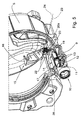
- a pin 20, preferably, but not necessarily, substantially cylindrical, is pivoted on the lifter 16, opportunely with a pivoting axis 23 substantially parallel to the pivoting axis 24 of the lifter 16; the pin 20 is slidably positioned into a suitable aperture 22, indicated in Figure 5 , provided in the frame 17 and in the lateral surface 6a of the drum 6, in such a way that the pin 20 can protrude radially from the lateral surface 6a of the drum 6, towards the tub 5.
- the aperture 22 is obtained only in the surface 6a of the drum 6.
- the position of the pin 20 is such that, by opportunely rotating the drum 6, the pin 20 can be positioned in correspondence of the seat 19.
- the pin 20 is pivoted on the lifter 16 in a region 23a of the latter comprised between the pivoting region 24a of the lifter 16 to the pivoting elements 21a, 21b, and the rear end 16a of the lifter 16, in such a way that by lifting the lifter 16, the pin 20 is moved towards the external of the drum 6.
- the length of the pin 20 is such that when the pin 20 is positioned in correspondence to the seat 19 and the lifter 16 is opened, as illustrated for example in Figures 4 and 5 , the pin 20 enters the seat 19, locking any further rotation of the drum 6; as indicated above, the pin 20 and the seat 19 are arranged in such a way that in this condition the opening 14 faces the housing 11, such that by opening the lifter 16, the user can accede to the housing 11, and therefore to the filter 12.
- the pin 20 engages the lateral surface 5a of the drum 5 (or a further element associated to the lateral surface 5a of the drum 5, for example the further frame 19a illustrated in Figures 8 , 12 and 16 ), and the lifter 16 can't therefore be completely opened.
- the lifter 16 can be opened only when the opening 14 is positioned in correspondence to the housing 11.
- closing device 15 comprising, instead of the lifter 16, another closing element, for example a lid, not illustrated, pivoted on a frame fixed to the drum 6, or directly to the latter.
- the washing machine comprises first elastic means adapted to press the pin 20 towards the inside of the drum 6; these first elastic means comprise, for example, a spring, not illustrated, provided around the pin 20 between the frame 17 (or the lateral surface 6a of the drum if the frame isn't provided), and a first protrusion 20a protruding from the pin 20 in proximity to the end of the latter pivoted on the lifter 16.
- first elastic means comprise, for example, a spring, not illustrated, provided around the pin 20 between the frame 17 (or the lateral surface 6a of the drum if the frame isn't provided), and a first protrusion 20a protruding from the pin 20 in proximity to the end of the latter pivoted on the lifter 16.
- the spring pushes the first protrusion 20a, and therefore the pin 20, towards the internal of the drum 6, in such a way that the lifter 16 stays in a stable closed position if no external actions are applied to it.
- the closing device 15 comprises also a locking/unlocking device 28, adapted for locking/unlocking the closing element (and therefore in this case the lifter 16) in/from the closed position;
- the locking/unlocking device 28 comprises a first arm 29, protruding from the frame 17, radially respect to the drum 6, and provided, in proximity of its free end, of a pawl 30, adapted to snap-fit, when the lifter 16 is in the closed position, with a suitable locking element, not illustrated, provided in the lifter 16.
- the user can disengage the pawl 30 from the locking element for example by a suitable button, not illustrated, provided on the lifter 16 and adapted to move the locking element in such a way to cause its disengagement form the pawl 30.
- FIG. 6 A second embodiment of the present invention is illustrated in Figures 6, 7 and 8 .
- the closing device 15 comprises a lifter 16 pivoted on two pivoting elements 21a, 21b protruding from a frame 17 fixed to the lateral surface 6a of the drum 6; obviously the frame 17 could be not provided, and the lifter 16 could be pivoted directly on the lateral surface 6a of the drum 6.
- the locking means comprise a pin 20, and a seat 19 provided on the tub 5, but in this case the pin 20 isn't pivoted on the lifter 16; in this embodiment the pin 20 is in fact associable to the drum 6 in a removable way.
- the pin 20 is cylindrical or prismatic, in order to be introduced, when the lifter 16 is closed, in a suitable first aperture 25, provided in the lifter 16, and in a second aperture 26, provided in the frame 17 (if present) and in the lateral surface 6a of the drum 6 in such a way that such a second aperture 26 faces the first aperture 25 when the lifter 16 is in the above mentioned closed position.
- the user can press the pin 20 towards the drum 5, until the pin 20 enters the seat 19, impeding the further rotation of the drum 6.
- the seat 19 and the pin 20 are arranged in such a way that in this position the opening 14 obtained in the drum 6 is placed above the housing 11 of the filter 12, such that by opening the lifter 16 it is possible to accede to the housing 11.
- the closing device 15 comprises a locking/unlocking device 28, adapted for locking/unlocking closing element (and therefore in this case the lifter 16) in/from the closed position; advantageously, as will be better explained in the following, the pin 20 interacts with the locking/unlocking device 28 when it is introduced into the second aperture 26, causing the unlocking of the lifter 16.
- the locking/unlocking device 28 comprises a first arm 29, protruding from the frame 17, radially respect to the drum 6, and provided, in proximity of its free end, of a pawl 30, adapted to snap-fit, when the lifter 16 is in the closed position, with a suitable locking element, not illustrated, provided in the lifter 16.
- the first arm 29 protrudes directly from the lateral surface 6a of the drum 6.
- the first arm 29 is associated to a movable element 31, provided on the frame 17, which can be elastically translated, by action of the pin 20 entering the second aperture 26, along an axis substantially perpendicular to the first arm 29; the introduction of the pin 20 in the second aperture 26 causes the movable element 31 to translate in a direction that causes the disengagement between the first arm 29 and the locking element provided in the lifter 16, and the consequent unlocking of the latter.
- the movable element 31 is a part of the frame 17, and is advantageously obtained by suitable carvings of the latter, which allows the elastic translation of the movable element 31 respect to the frame 17.
- the movable element 31 has a rounded and/or inclined end 31a (illustrated in Figure 8 ) constituting part of the border of the second aperture 26, such as to engage the pin 20 when the latter is inserted in the second aperture 26.
- a rounded and/or inclined end 31a (illustrated in Figure 8 ) constituting part of the border of the second aperture 26, such as to engage the pin 20 when the latter is inserted in the second aperture 26.
- the movable element is provided directly in the lateral surface 6a of the drum 6.
- the washing machine 1 can comprise elastic means, such as a spring, or a gas spring, not illustrated, adapted to cause the automatic opening of the lifter 16 as soon as it is unlocked, that is as soon as the first arm 29 disengages the locking element provided in the lifter 16.
- elastic means such as a spring, or a gas spring, not illustrated, adapted to cause the automatic opening of the lifter 16 as soon as it is unlocked, that is as soon as the first arm 29 disengages the locking element provided in the lifter 16.
- these elastic means aren't provided, and the lifter 16 has to be manually opened after the unlocking of the locking/unlocking device 28 due to the introduction of the pin 20 into the second aperture 26; in this case the lifter 16 is provided of suitable grasping means, comprising, for example, one or more grasping cavities 32, obtained on its upper surface.
- the pin 20 can be a dedicated device, or it can be a suitable cylindrical or prismatic object, for example a pen, a pencil, a screwdriver, etc.
- a closing device 15 comprising, instead of the lifter 16, for example a lid or a porthole, not illustrated, pivoted on a frame fixed to the drum 6, or directly to the latter.
- FIG. 9 A third embodiment of the present invention is illustrated in Figures 9, 10, 11 and 12 .
- the closing device 15 comprises a lifter 16 pivoted on two pivoting elements 21a, 21b protruding from a frame 17 fixed to the lateral surface 6a of the drum 6; obviously the frame 17 could be not provided, and the lifter 16 could be pivoted directly on pivoting elements provided on the lateral surface 6a of the drum 6.
- the locking means comprise a pin 20, preferably cylindrical or prismatic, permanently associated to the drum 6 and to the frame 17 (only to the drum 6 if the frame 17 isn't provided); as illustrated for example in Figures 9 and 11 , the pin 20 ins't accessible by the user when the lifter 16 is closed, since the lifter 16 covers completely such a pin 20.
- the pin 20 can translate substantially radially respect to the lateral surface 6a of the drum 6.
- the pin 20 is associated to a first end of 33a of a lever 33, pivoted on the frame 17 (or directly to the drum 6 if the frame 17 isn't provided).
- the lever 33 is preferably provided with elastic means, not illustrated, such as a spring, which allows a stable positioning of the lever 33 in two distinct angular positions, one, called external position and illustrated in Figure 11 , in which the pin 20 is positioned at an higher distance from the underlying tub 5, and the other, called internal position and illustrated in Figure 12 , in which the pin 20 is positioned at a lower distance from the underlying tub 5.
- elastic means not illustrated, such as a spring
- the closing device 15 comprises a locking/unlocking device adapted for locking/unlocking the lifter 16 in/from the closed position; in this case the locking/unlocking device comprises a second end 33b of the lever 33, which is substantially "U-shaped", in order to engage and lock, when the lifter 16 is in the closed position and the pin 20 is in the external position, a second arm 34 protruding from the lifter 16, such as to lock the lifter 16 in the closed position.
- the pin 20, the first and second extremities 33a and 33b of the lever 33, and the second arm 34 are arranged in such a way that by manually lifting the lifter 16, the consequent movement upwards of the second arm 34 causes the lever 33 to rotate in such a way that its first end 33a pushes the pin 20 towards the tub 5.
- the length of the pin 20 is such that if the drum 6 is rotated in such a way that the pin 20 isn't positioned in correspondence to the seat 19, and the user tries to lift the lifter 16, the pin 20 is pushed by the lever 33 towards the tub 5, and engages the lateral surface 5a of the latter, not allowing the full opening of the lifter 16.
- the lifter 16 can therefore be opened only if the drum 6 is rotated in such a way that the pin 20 is positioned above the seat 19; in this position, by opening the lifter 16, the pin 20 is introduced in the seat 19, and locks the rotation of the drum 6; in this way it is very easy to find the correct angular position of the drum 6 which allows the opening of the lifter 16.
- the pin 20 and the seat 19 are arranged in such a way that when the pin 20 is positioned in correspondence to the seat 19, the opening 14 provided in the drum 6 faces the housing 11, such that by opening the lifter 16 it is possible to accede to the housing 11.
- a closing device 15 comprising, instead of the lifter 16, for example a lid, not illustrated, pivoted on a frame fixed to the drum 6, or directly to the latter.
- FIG. 13 to 16 A fourth embodiment of the present invention is illustrated in Figures 13 to 16 .
- the closing device 15 comprises a lifter 16 pivoted on two pivoting elements 21a, 21b protruding from a frame 17 fixed to the lateral surface 6a of the drum 6; obviously the frame 17 could be not provided, and the lifter 16 could be pivoted directly on pivoting elements provided on the lateral surface 6a of the drum 6.
- the pin 20, preferably cylindrical or prismatic, is permanently associated to the drum 6 and to the frame 17 (only to the drum 6 if the frame 17 isn't provided), and it is accessible by the user towards a suitable opening 35 obtained in the lifter 16; advantageously the pin 20 can translate substantially radially respect to the lateral surface 6a of the drum 6.
- the pin 20 is associated to a first end of 33a of a lever 33, pivoted on the frame 17 (or directly to the drum 6 if the frame 17 isn't provided).
- the lever 33 is preferably provided with elastic means, not illustrated, such as a spring, which allows a stable positioning of such a lever 33 in two distinct angular positions, one, called external position and illustrated in Figure 15 , in which the pin 20 is positioned at an higher distance from the underlying tub 5, and the other, called internal position and illustrated in Figure 16 , in which the pin 20 is positioned at a lower distance from the underlying tub 5.
- the closing device 15 comprises a locking/unlocking device adapted for locking/unlocking the lifter 16 in/from the closed position; also in this case the locking/unlocking device comprises a second end 33b of the lever 33, which is substantially "U-shaped", in order to engage and lock, when the lifter 16 is in the closed position and the pin 20 is in the external position, a second arm 34 protruding from the lifter 16, such as to lock the lifter 16 in the closed position.
- the pin 20, the first and second extremities 33a and 33b of the lever 33, and the second arm 34 are arranged in such a way that when the pin 20 is moved towards the underlying tub 5, the second end 33b of the lever 33 rotates towards the lifter 16, so as to unlock the second arm 34; in this condition the lifter 16 can be manually lifted, or, if the pivoting means are provided with elastic means which tends to open the lifter 16, the latter is automatically opened as soon as the second arm 34 is unlocked.
- the length of the pin 20 is such that if the drum 6 is rotated in such a way that the pin 20 isn't positioned above the seat 19, and the user tries to press the pin 20 towards the tub 5, for example by using a suitable tool, like a screwdriver or a pen, or also by a finger, the pin 20 translates towards the tub 5, and engages the lateral surface 5a of the latter, not allowing the unlocking of the second arm 34, and therefore not allowing the opening of the lifter 16.
- the lifter 16 can therefore be opened only if the pin 20 is positioned above the seat 19; in this position, by pushing the pin 20 towards the tub 5, the pin 20 is introduced in the seat 19, locking the rotation of the drum 6, and contemporaneously the second arm 34 is unlocked, allowing the opening of the lifter 16. In this way it is very easy for a user to find the correct angular position of the drum 6 which allows the opening of the lifter 16.
- the pin 20 and the seat 19 are arranged in such a way that when the pin 20 is positioned in correspondence to the seat 19, the opening 14 of the drum 6 faces the housing 11, such that by opening the lifter 16 it is possible to accede to the housing 11.
- the closing device 15 comprises, instead of the lifter 16, for example a lid, not illustrated, pivoted on a frame fixed to the drum 6, or directly to the latter.
- a fifth embodiment of the invention is illustrated in Figures 17 to 20 .
- a cavity 36 adapted to temporarily lodge the pin 20, is provided in a frontal side 17a of the frame 17 opposite to the pivoting elements 21a, 21b on which the lifter 16 is pivoted (if the frame 17 isn't provided, the cavity 36 is obtained directly on the lateral surface 6a of the drum 6); advantageously the cavity 36 has an elongated shape.
- the pin 20 is provided, in correspondence of a first end 20a, with a pivoting element 37, protruding from its lateral surface 20b opposite to the lifter 16.
- a pivoting element 37 protruding from its lateral surface 20b opposite to the lifter 16.
- an analogous further pivoting element protrudes from the lateral surface of the pin 20 facing the lifter 16.
- a housing 38 for the pivoting element 37 is obtained at one side of the cavity 37, adapted to allow the rotation of the pin 20 with respect to the cavity 36 when the pivoting element 37 is positioned in the housing 38.
- the pin 20 can rotate, with respect to the cavity 37, from an inner position, illustrated in Figure 18 , in which it is substantially fully contained in the cavity 37, to an outer position, illustrated in Figure 19 , in which it protrudes externally from the cavity 37, and is positioned substantially perpendicular to the cavity 37.
- the housing 38 is opened towards the tub 5, in such a way that the pivoting element 37 can exit from the housing 38 when the pin 20 is in the outer position, as illustrated in Figure 20 .
- the pin 20 After the pin 20 has been taken in the outer position, it can be pushed towards the tub 5, and, if the pin 20 is positioned above the seat 19, the pin 20 is introduced in the seat 19, locking the rotation of the drum 6 with respect to the tub 5.
- the pin 20 isn't positioned above the seat 19, and a user, after taking the pin 20 in the outer position, tries to push the pin 20 towards the tub 5, the pin 20 engages the lateral surface 5a of the latter, and the rotation of the drum 6 isn't locked.
- the pin 20 is provided with a handle 39 for its lifting.
- the washing machine 1 comprises a locking/unlocking device adapted for locking/unlocking the lifter 16 in/from the closed position;
- the locking/unlocking device comprise a lip 40 protruding from the end of the lifter 16 opposite to the pivoting elements 21a, 21b on which it is pivoted; opportunely the lip 40 is arranged in such a way that when the lifter 16 is in the closed position and the pin 20 is placed in the cavity 36 in the inner position (as illustrated for example in figure 18 ), the pin 20 leans on the lip 40, and the lifter 16 can't therefore be lifted; the lifter 16 can therefore be opened only after the pin 20 has been lifted and taken in the outer position.
- the closing device 28, adapted for locking/unlocking the lifter 16 in/from the closed position comprises also the pin 20.
- the closing device 15 comprises, instead of the lifter 16, for example a lid, not illustrated, pivoted on a frame fixed to the drum 6, or directly to the latter.
- a pin 20 protrudes substantially radially from the lateral surface 6a of the drum 6, so as to engage a seat 19 provided on the lateral surface 5a of the tub 5.
- the pin 20 protrudes from the rear end 6b of the drum 6, and the seat 19 is provided on the rear end 5b of the tub 5 facing the rear end 6b of the drum 6; in the same way in another embodiment, not illustrated, the pin 20 and the seat 19 can be associated respectively to a frontal end 6d of the drum 6, and to a frontal end 5d of the tub 5.
- the drum can be taken and locked in the particular angular position in which the opening 14 of the drum faces the housing 11 for the filter, by a suitable programming of the electric drive which controls the electric motor adapted rotate the drum 6.
- the electric motor can be directly mounted on the drum (or on a rotating shaft, not illustrated, associated to the drum), or it can also be connected to the drum via a suitable belt pulley.
- the electric motor is a step motor (but it is clear that other kinds of electric motors could be used).
- the electric drive of the electric motor of a washing machine is controlled by a programmable electronic board adapted to control the various functions of the machine (e.g. the washing phases, the rotary speed of the drum, etc.).
- the electric motor rotates the drum 6 up to reach the angular position in which the opening 14 faces the housing 11, and locks the drum 6 in such a position, so as to allow the access to the filter, for example for its removing/repositioning and/or for its cleaning and/or inspecting.
- the electronic board of the washing machine can be programmed in such a way that as soon as a user opens the loading/unloading door, the drum 6 is automatically rotated and locked by the electric motor in the position in which the opening 14 faces the housing 11, so as to allow the access to the filter.
- the locking means comprise the electric motor and its electric drive.
- the locking of the drum is obtained by other suitable means, comprising, for example, suitable brakes, not illustrated, controlled, for example, by the electronic board of the washing machine, and adapted to lock the drum, or the belt pulley, or the drum shaft.
- the locking means comprise, for example a magnet, not illustrated, provided at/to the drum 6, preferably on its lateral surface 6a, and an electromagnet, also not illustrated, provided externally to the tub and preferably electrically powered by the electronic board of the washing machine.
- the magnet and the electromagnet are arranged in such a way that when the electromagnet is electrically powered, it generates a magnetic field which causes the drum 6 to rotate until the magnet provided at/to the latter faces the electromagnet; opportunely the reciprocal position of the magnet and of the electromagnet is such that when the magnet faces the electromagnet, the opening 14 of the drum 6 faces the housing 11 of the tub, so as to allow the aces to the filter.
- the electronic board is in this case programmed in such a way that after the detection, for example by a sensor or a switch, of a specific event (e.g. the opening of the loading/unloading door), the electromagnet is powered, so as to cause, as explained above, the rotation of the drum 6 and the positioning of the opening 14 in correspondence of the housing 11.
- the electromagnet isn't electrically powered and controlled by the electronic board of the washing machine, but by a dedicated device, for example another electronic board, or simply by an electric switch connecting the electromagnet to a power source; in this last case, a user can act on the switch in order to activate the electromagnet and to cause the rotation of the drum.
- a washing machine which, thanks to the locking means which impede the rotation of the drum with respect to the tub only when the opening obtained in the drum faces the housing for the filter, facilitates the access to the filter, and therefore the operations of removing/repositioning the filter from/to the housing, and/or the cleaning and/or the inspection of the filter.
- the invention facilitates and speeds up the reaching the angular-positioning of the drum allowing the access to the filter housing.
- the fact that the rotation of the drum is locked when the lift is opened and the opening of the drum is positioned above the filter housing allows a safe access to the filter, without the risk of injuring the user or to brake the filter.
Landscapes
- Engineering & Computer Science (AREA)
- Textile Engineering (AREA)
- Main Body Construction Of Washing Machines And Laundry Dryers (AREA)
Priority Applications (2)
| Application Number | Priority Date | Filing Date | Title |
|---|---|---|---|
| AT09006394T ATE549445T1 (de) | 2009-05-12 | 2009-05-12 | Waschmaschine |
| EP09006394A EP2251477B1 (fr) | 2009-05-12 | 2009-05-12 | Machine à laver |
Applications Claiming Priority (1)
| Application Number | Priority Date | Filing Date | Title |
|---|---|---|---|
| EP09006394A EP2251477B1 (fr) | 2009-05-12 | 2009-05-12 | Machine à laver |
Publications (2)
| Publication Number | Publication Date |
|---|---|
| EP2251477A1 true EP2251477A1 (fr) | 2010-11-17 |
| EP2251477B1 EP2251477B1 (fr) | 2012-03-14 |
Family
ID=41136786
Family Applications (1)
| Application Number | Title | Priority Date | Filing Date |
|---|---|---|---|
| EP09006394A Not-in-force EP2251477B1 (fr) | 2009-05-12 | 2009-05-12 | Machine à laver |
Country Status (2)
| Country | Link |
|---|---|
| EP (1) | EP2251477B1 (fr) |
| AT (1) | ATE549445T1 (fr) |
Cited By (11)
| Publication number | Priority date | Publication date | Assignee | Title |
|---|---|---|---|---|
| EP2503050A1 (fr) * | 2011-03-24 | 2012-09-26 | Electrolux Home Products Corporation N.V. | Machine à laver équipée d'un élément filtrant |
| EP2706139A1 (fr) * | 2012-09-07 | 2014-03-12 | Electrolux Home Products Corporation N.V. | Améliorations apportées à un agencement de filtre de circuit de drainage pour appareils de lavage |
| FR3044025A1 (fr) * | 2015-11-19 | 2017-05-26 | Groupe Brandt | Tambour de machine a laver le linge comportant une trappe d'acces |
| RU2731611C1 (ru) * | 2019-02-01 | 2020-09-07 | ЭлДжи ЭЛЕКТРОНИКС ИНК. | Устройство для обработки белья |
| RU2735226C1 (ru) * | 2019-02-01 | 2020-10-29 | ЭлДжи ЭЛЕКТРОНИКС ИНК. | Устройство для обработки белья |
| WO2020238654A1 (fr) * | 2019-05-28 | 2020-12-03 | 青岛海尔滚筒洗衣机有限公司 | Dispositif de levage de linge pour machine à laver et machine à laver à tambour |
| WO2020251513A3 (fr) * | 2019-06-14 | 2021-01-21 | Arcelik Anonim Sirketi | Machine à laver comprenant un élément de filtration |
| EP3875663A1 (fr) * | 2020-03-06 | 2021-09-08 | LG Electronics Inc. | Appareil de traitement du linge |
| EP3875662A1 (fr) * | 2020-03-06 | 2021-09-08 | LG Electronics Inc. | Appareil de traitement du linge |
| US11408109B2 (en) | 2019-02-01 | 2022-08-09 | Lg Electronics Inc. | Laundry treating apparatus |
| US11414802B2 (en) | 2019-02-01 | 2022-08-16 | Lg Electronics Inc. | Laundry treating apparatus |
Families Citing this family (1)
| Publication number | Priority date | Publication date | Assignee | Title |
|---|---|---|---|---|
| CN108642800A (zh) * | 2018-07-04 | 2018-10-12 | 无锡小天鹅股份有限公司 | 滚筒洗衣机及其桶组件 |
Citations (4)
| Publication number | Priority date | Publication date | Assignee | Title |
|---|---|---|---|---|
| GB1197919A (en) | 1966-10-08 | 1970-07-08 | Candy Spa | Improvements to Linen Washing and Like Machines |
| FR2190966A1 (fr) | 1972-07-05 | 1974-02-01 | Chalectro | |
| FR2778678A1 (fr) * | 1998-05-15 | 1999-11-19 | Ciapem | Dispositif d'ouverture automatique du portillon d'une machine a laver ou secher le linge |
| EP1849904A1 (fr) | 2006-04-27 | 2007-10-31 | Electrolux Home Products Corporation N.V. | Appareil d'accès au filtre de vidange à fermeture automatique pour une machine à laver à chargement par le haut |
-
2009
- 2009-05-12 EP EP09006394A patent/EP2251477B1/fr not_active Not-in-force
- 2009-05-12 AT AT09006394T patent/ATE549445T1/de active
Patent Citations (4)
| Publication number | Priority date | Publication date | Assignee | Title |
|---|---|---|---|---|
| GB1197919A (en) | 1966-10-08 | 1970-07-08 | Candy Spa | Improvements to Linen Washing and Like Machines |
| FR2190966A1 (fr) | 1972-07-05 | 1974-02-01 | Chalectro | |
| FR2778678A1 (fr) * | 1998-05-15 | 1999-11-19 | Ciapem | Dispositif d'ouverture automatique du portillon d'une machine a laver ou secher le linge |
| EP1849904A1 (fr) | 2006-04-27 | 2007-10-31 | Electrolux Home Products Corporation N.V. | Appareil d'accès au filtre de vidange à fermeture automatique pour une machine à laver à chargement par le haut |
Cited By (19)
| Publication number | Priority date | Publication date | Assignee | Title |
|---|---|---|---|---|
| EP2503050A1 (fr) * | 2011-03-24 | 2012-09-26 | Electrolux Home Products Corporation N.V. | Machine à laver équipée d'un élément filtrant |
| EP2706139A1 (fr) * | 2012-09-07 | 2014-03-12 | Electrolux Home Products Corporation N.V. | Améliorations apportées à un agencement de filtre de circuit de drainage pour appareils de lavage |
| WO2014037455A1 (fr) * | 2012-09-07 | 2014-03-13 | Electrolux Home Products Corporation N.V. | Perfectionnements d'agencement de filtre de circuit de drainage pour appareils de lavage |
| FR3044025A1 (fr) * | 2015-11-19 | 2017-05-26 | Groupe Brandt | Tambour de machine a laver le linge comportant une trappe d'acces |
| US12227890B2 (en) | 2019-02-01 | 2025-02-18 | Lg Electronics Inc. | Laundry treating apparatus |
| RU2735226C1 (ru) * | 2019-02-01 | 2020-10-29 | ЭлДжи ЭЛЕКТРОНИКС ИНК. | Устройство для обработки белья |
| RU2731611C1 (ru) * | 2019-02-01 | 2020-09-07 | ЭлДжи ЭЛЕКТРОНИКС ИНК. | Устройство для обработки белья |
| US11408109B2 (en) | 2019-02-01 | 2022-08-09 | Lg Electronics Inc. | Laundry treating apparatus |
| US11268229B2 (en) | 2019-02-01 | 2022-03-08 | Lg Electronics Inc. | Laundry treating apparatus |
| US11286606B2 (en) | 2019-02-01 | 2022-03-29 | Lg Electronics Inc. | Laundry treating apparatus |
| US11414802B2 (en) | 2019-02-01 | 2022-08-16 | Lg Electronics Inc. | Laundry treating apparatus |
| WO2020238654A1 (fr) * | 2019-05-28 | 2020-12-03 | 青岛海尔滚筒洗衣机有限公司 | Dispositif de levage de linge pour machine à laver et machine à laver à tambour |
| WO2020251513A3 (fr) * | 2019-06-14 | 2021-01-21 | Arcelik Anonim Sirketi | Machine à laver comprenant un élément de filtration |
| EP3875663A1 (fr) * | 2020-03-06 | 2021-09-08 | LG Electronics Inc. | Appareil de traitement du linge |
| AU2021201443B2 (en) * | 2020-03-06 | 2022-07-21 | Lg Electronics Inc. | Laundry treating apparatus |
| US11566364B2 (en) | 2020-03-06 | 2023-01-31 | Lg Electronics Inc. | Laundry treating apparatus |
| US11674254B2 (en) | 2020-03-06 | 2023-06-13 | Lg Electronics Inc. | Laundry treating apparatus |
| US12012687B2 (en) | 2020-03-06 | 2024-06-18 | Lg Electronics Inc. | Laundry treating apparatus |
| EP3875662A1 (fr) * | 2020-03-06 | 2021-09-08 | LG Electronics Inc. | Appareil de traitement du linge |
Also Published As
| Publication number | Publication date |
|---|---|
| ATE549445T1 (de) | 2012-03-15 |
| EP2251477B1 (fr) | 2012-03-14 |
Similar Documents
| Publication | Publication Date | Title |
|---|---|---|
| EP2251477B1 (fr) | Machine à laver | |
| KR100630023B1 (ko) | 드럼식 세탁 건조기 | |
| KR20090096949A (ko) | 의류처리장치 및 그 제어방법 | |
| EP2876197B1 (fr) | Machine à laver avec ensemble tiroir | |
| CN105671869A (zh) | 洗衣机 | |
| KR101636074B1 (ko) | 드럼세탁기 | |
| US10815609B2 (en) | Front load washing machine appliance equipped with door reversing locking and latching features | |
| CN102071560B (zh) | 具有改进的用于排水回路的过滤器的洗衣机 | |
| EP2385166A1 (fr) | Machine à laver | |
| RU2423564C2 (ru) | Средство для доступа к сливному фильтру стиральной машины с верхней загрузкой | |
| US11718948B2 (en) | Laundry treatment appliance with improved drawer | |
| KR101391735B1 (ko) | 드럼세탁기 | |
| EP2889419B1 (fr) | Machine à laver le linge | |
| US10822733B2 (en) | Washing machine appliance lid assembly including a retractable hanger | |
| US11939717B2 (en) | Hinge assembly for an appliance | |
| EP2280113A1 (fr) | Machine à laver et ensemble de filtrage pour le circuit de drainage d'une machine à laver | |
| KR101082886B1 (ko) | 세탁기의 세탁조 세정 방법 | |
| JP2008194342A (ja) | 洗濯乾燥機 | |
| EP2280112A1 (fr) | Machine à laver et ensemble de filtrage pour le circuit de drainage d'une machine à laver | |
| EP2706139A1 (fr) | Améliorations apportées à un agencement de filtre de circuit de drainage pour appareils de lavage | |
| KR20070088914A (ko) | 세제박스의 개폐구조 | |
| KR100479094B1 (ko) | 세탁기 | |
| KR200464784Y1 (ko) | 드럼 세탁기 | |
| KR101306035B1 (ko) | 세탁물 오염 방지용 세탁기 | |
| KR102057861B1 (ko) | 의류처리장치 |
Legal Events
| Date | Code | Title | Description |
|---|---|---|---|
| PUAI | Public reference made under article 153(3) epc to a published international application that has entered the european phase |
Free format text: ORIGINAL CODE: 0009012 |
|
| AK | Designated contracting states |
Kind code of ref document: A1 Designated state(s): AT BE BG CH CY CZ DE DK EE ES FI FR GB GR HR HU IE IS IT LI LT LU LV MC MK MT NL NO PL PT RO SE SI SK TR |
|
| AX | Request for extension of the european patent |
Extension state: AL BA RS |
|
| RAP1 | Party data changed (applicant data changed or rights of an application transferred) |
Owner name: ELECTROLUX HOME PRODUCTS CORPORATION N.V. |
|
| 17P | Request for examination filed |
Effective date: 20110517 |
|
| RAP1 | Party data changed (applicant data changed or rights of an application transferred) |
Owner name: ELECTROLUX HOME PRODUCTS CORPORATION N.V. |
|
| GRAP | Despatch of communication of intention to grant a patent |
Free format text: ORIGINAL CODE: EPIDOSNIGR1 |
|
| RIC1 | Information provided on ipc code assigned before grant |
Ipc: D06F 37/06 20060101AFI20110914BHEP Ipc: D06F 39/10 20060101ALI20110914BHEP |
|
| GRAS | Grant fee paid |
Free format text: ORIGINAL CODE: EPIDOSNIGR3 |
|
| GRAA | (expected) grant |
Free format text: ORIGINAL CODE: 0009210 |
|
| AK | Designated contracting states |
Kind code of ref document: B1 Designated state(s): AT BE BG CH CY CZ DE DK EE ES FI FR GB GR HR HU IE IS IT LI LT LU LV MC MK MT NL NO PL PT RO SE SI SK TR |
|
| REG | Reference to a national code |
Ref country code: GB Ref legal event code: FG4D |
|
| REG | Reference to a national code |
Ref country code: AT Ref legal event code: REF Ref document number: 549445 Country of ref document: AT Kind code of ref document: T Effective date: 20120315 Ref country code: CH Ref legal event code: EP |
|
| REG | Reference to a national code |
Ref country code: IE Ref legal event code: FG4D |
|
| REG | Reference to a national code |
Ref country code: DE Ref legal event code: R096 Ref document number: 602009005832 Country of ref document: DE Effective date: 20120510 |
|
| REG | Reference to a national code |
Ref country code: NL Ref legal event code: VDEP Effective date: 20120314 |
|
| PG25 | Lapsed in a contracting state [announced via postgrant information from national office to epo] |
Ref country code: HR Free format text: LAPSE BECAUSE OF FAILURE TO SUBMIT A TRANSLATION OF THE DESCRIPTION OR TO PAY THE FEE WITHIN THE PRESCRIBED TIME-LIMIT Effective date: 20120314 Ref country code: NO Free format text: LAPSE BECAUSE OF FAILURE TO SUBMIT A TRANSLATION OF THE DESCRIPTION OR TO PAY THE FEE WITHIN THE PRESCRIBED TIME-LIMIT Effective date: 20120614 Ref country code: LT Free format text: LAPSE BECAUSE OF FAILURE TO SUBMIT A TRANSLATION OF THE DESCRIPTION OR TO PAY THE FEE WITHIN THE PRESCRIBED TIME-LIMIT Effective date: 20120314 |
|
| LTIE | Lt: invalidation of european patent or patent extension |
Effective date: 20120314 |
|
| PG25 | Lapsed in a contracting state [announced via postgrant information from national office to epo] |
Ref country code: FI Free format text: LAPSE BECAUSE OF FAILURE TO SUBMIT A TRANSLATION OF THE DESCRIPTION OR TO PAY THE FEE WITHIN THE PRESCRIBED TIME-LIMIT Effective date: 20120314 Ref country code: GR Free format text: LAPSE BECAUSE OF FAILURE TO SUBMIT A TRANSLATION OF THE DESCRIPTION OR TO PAY THE FEE WITHIN THE PRESCRIBED TIME-LIMIT Effective date: 20120615 Ref country code: LV Free format text: LAPSE BECAUSE OF FAILURE TO SUBMIT A TRANSLATION OF THE DESCRIPTION OR TO PAY THE FEE WITHIN THE PRESCRIBED TIME-LIMIT Effective date: 20120314 |
|
| REG | Reference to a national code |
Ref country code: AT Ref legal event code: MK05 Ref document number: 549445 Country of ref document: AT Kind code of ref document: T Effective date: 20120314 |
|
| PG25 | Lapsed in a contracting state [announced via postgrant information from national office to epo] |
Ref country code: CY Free format text: LAPSE BECAUSE OF FAILURE TO SUBMIT A TRANSLATION OF THE DESCRIPTION OR TO PAY THE FEE WITHIN THE PRESCRIBED TIME-LIMIT Effective date: 20120314 |
|
| PG25 | Lapsed in a contracting state [announced via postgrant information from national office to epo] |
Ref country code: IS Free format text: LAPSE BECAUSE OF FAILURE TO SUBMIT A TRANSLATION OF THE DESCRIPTION OR TO PAY THE FEE WITHIN THE PRESCRIBED TIME-LIMIT Effective date: 20120714 Ref country code: RO Free format text: LAPSE BECAUSE OF FAILURE TO SUBMIT A TRANSLATION OF THE DESCRIPTION OR TO PAY THE FEE WITHIN THE PRESCRIBED TIME-LIMIT Effective date: 20120314 Ref country code: SI Free format text: LAPSE BECAUSE OF FAILURE TO SUBMIT A TRANSLATION OF THE DESCRIPTION OR TO PAY THE FEE WITHIN THE PRESCRIBED TIME-LIMIT Effective date: 20120314 Ref country code: BE Free format text: LAPSE BECAUSE OF FAILURE TO SUBMIT A TRANSLATION OF THE DESCRIPTION OR TO PAY THE FEE WITHIN THE PRESCRIBED TIME-LIMIT Effective date: 20120314 Ref country code: SE Free format text: LAPSE BECAUSE OF FAILURE TO SUBMIT A TRANSLATION OF THE DESCRIPTION OR TO PAY THE FEE WITHIN THE PRESCRIBED TIME-LIMIT Effective date: 20120314 Ref country code: CZ Free format text: LAPSE BECAUSE OF FAILURE TO SUBMIT A TRANSLATION OF THE DESCRIPTION OR TO PAY THE FEE WITHIN THE PRESCRIBED TIME-LIMIT Effective date: 20120314 Ref country code: EE Free format text: LAPSE BECAUSE OF FAILURE TO SUBMIT A TRANSLATION OF THE DESCRIPTION OR TO PAY THE FEE WITHIN THE PRESCRIBED TIME-LIMIT Effective date: 20120314 Ref country code: PL Free format text: LAPSE BECAUSE OF FAILURE TO SUBMIT A TRANSLATION OF THE DESCRIPTION OR TO PAY THE FEE WITHIN THE PRESCRIBED TIME-LIMIT Effective date: 20120314 |
|
| PG25 | Lapsed in a contracting state [announced via postgrant information from national office to epo] |
Ref country code: PT Free format text: LAPSE BECAUSE OF FAILURE TO SUBMIT A TRANSLATION OF THE DESCRIPTION OR TO PAY THE FEE WITHIN THE PRESCRIBED TIME-LIMIT Effective date: 20120716 Ref country code: SK Free format text: LAPSE BECAUSE OF FAILURE TO SUBMIT A TRANSLATION OF THE DESCRIPTION OR TO PAY THE FEE WITHIN THE PRESCRIBED TIME-LIMIT Effective date: 20120314 |
|
| PG25 | Lapsed in a contracting state [announced via postgrant information from national office to epo] |
Ref country code: MC Free format text: LAPSE BECAUSE OF NON-PAYMENT OF DUE FEES Effective date: 20120531 |
|
| PLBE | No opposition filed within time limit |
Free format text: ORIGINAL CODE: 0009261 |
|
| STAA | Information on the status of an ep patent application or granted ep patent |
Free format text: STATUS: NO OPPOSITION FILED WITHIN TIME LIMIT |
|
| PG25 | Lapsed in a contracting state [announced via postgrant information from national office to epo] |
Ref country code: AT Free format text: LAPSE BECAUSE OF FAILURE TO SUBMIT A TRANSLATION OF THE DESCRIPTION OR TO PAY THE FEE WITHIN THE PRESCRIBED TIME-LIMIT Effective date: 20120314 Ref country code: DK Free format text: LAPSE BECAUSE OF FAILURE TO SUBMIT A TRANSLATION OF THE DESCRIPTION OR TO PAY THE FEE WITHIN THE PRESCRIBED TIME-LIMIT Effective date: 20120314 Ref country code: NL Free format text: LAPSE BECAUSE OF FAILURE TO SUBMIT A TRANSLATION OF THE DESCRIPTION OR TO PAY THE FEE WITHIN THE PRESCRIBED TIME-LIMIT Effective date: 20120314 |
|
| 26N | No opposition filed |
Effective date: 20121217 |
|
| REG | Reference to a national code |
Ref country code: IE Ref legal event code: MM4A |
|
| PG25 | Lapsed in a contracting state [announced via postgrant information from national office to epo] |
Ref country code: MK Free format text: LAPSE BECAUSE OF FAILURE TO SUBMIT A TRANSLATION OF THE DESCRIPTION OR TO PAY THE FEE WITHIN THE PRESCRIBED TIME-LIMIT Effective date: 20120314 |
|
| REG | Reference to a national code |
Ref country code: DE Ref legal event code: R097 Ref document number: 602009005832 Country of ref document: DE Effective date: 20121217 |
|
| PG25 | Lapsed in a contracting state [announced via postgrant information from national office to epo] |
Ref country code: IE Free format text: LAPSE BECAUSE OF NON-PAYMENT OF DUE FEES Effective date: 20120512 Ref country code: ES Free format text: LAPSE BECAUSE OF FAILURE TO SUBMIT A TRANSLATION OF THE DESCRIPTION OR TO PAY THE FEE WITHIN THE PRESCRIBED TIME-LIMIT Effective date: 20120625 |
|
| PG25 | Lapsed in a contracting state [announced via postgrant information from national office to epo] |
Ref country code: MT Free format text: LAPSE BECAUSE OF FAILURE TO SUBMIT A TRANSLATION OF THE DESCRIPTION OR TO PAY THE FEE WITHIN THE PRESCRIBED TIME-LIMIT Effective date: 20120314 Ref country code: BG Free format text: LAPSE BECAUSE OF FAILURE TO SUBMIT A TRANSLATION OF THE DESCRIPTION OR TO PAY THE FEE WITHIN THE PRESCRIBED TIME-LIMIT Effective date: 20120614 |
|
| REG | Reference to a national code |
Ref country code: CH Ref legal event code: PL |
|
| PG25 | Lapsed in a contracting state [announced via postgrant information from national office to epo] |
Ref country code: LI Free format text: LAPSE BECAUSE OF NON-PAYMENT OF DUE FEES Effective date: 20130531 Ref country code: CH Free format text: LAPSE BECAUSE OF NON-PAYMENT OF DUE FEES Effective date: 20130531 |
|
| PG25 | Lapsed in a contracting state [announced via postgrant information from national office to epo] |
Ref country code: TR Free format text: LAPSE BECAUSE OF FAILURE TO SUBMIT A TRANSLATION OF THE DESCRIPTION OR TO PAY THE FEE WITHIN THE PRESCRIBED TIME-LIMIT Effective date: 20120314 |
|
| PG25 | Lapsed in a contracting state [announced via postgrant information from national office to epo] |
Ref country code: LU Free format text: LAPSE BECAUSE OF NON-PAYMENT OF DUE FEES Effective date: 20120512 |
|
| PG25 | Lapsed in a contracting state [announced via postgrant information from national office to epo] |
Ref country code: HU Free format text: LAPSE BECAUSE OF FAILURE TO SUBMIT A TRANSLATION OF THE DESCRIPTION OR TO PAY THE FEE WITHIN THE PRESCRIBED TIME-LIMIT Effective date: 20090512 |
|
| REG | Reference to a national code |
Ref country code: FR Ref legal event code: PLFP Year of fee payment: 8 |
|
| PGFP | Annual fee paid to national office [announced via postgrant information from national office to epo] |
Ref country code: FR Payment date: 20160520 Year of fee payment: 8 |
|
| REG | Reference to a national code |
Ref country code: FR Ref legal event code: ST Effective date: 20180131 |
|
| PG25 | Lapsed in a contracting state [announced via postgrant information from national office to epo] |
Ref country code: FR Free format text: LAPSE BECAUSE OF NON-PAYMENT OF DUE FEES Effective date: 20170531 |
|
| PGFP | Annual fee paid to national office [announced via postgrant information from national office to epo] |
Ref country code: IT Payment date: 20220524 Year of fee payment: 14 Ref country code: GB Payment date: 20220520 Year of fee payment: 14 Ref country code: DE Payment date: 20220519 Year of fee payment: 14 |
|
| REG | Reference to a national code |
Ref country code: DE Ref legal event code: R119 Ref document number: 602009005832 Country of ref document: DE |
|
| GBPC | Gb: european patent ceased through non-payment of renewal fee |
Effective date: 20230512 |
|
| PG25 | Lapsed in a contracting state [announced via postgrant information from national office to epo] |
Ref country code: IT Free format text: LAPSE BECAUSE OF NON-PAYMENT OF DUE FEES Effective date: 20230512 Ref country code: DE Free format text: LAPSE BECAUSE OF NON-PAYMENT OF DUE FEES Effective date: 20231201 Ref country code: GB Free format text: LAPSE BECAUSE OF NON-PAYMENT OF DUE FEES Effective date: 20230512 |