EP2253471A1 - Cylindre de pression doté d'un tissu en caoutchouc pour une presse rotative offset à rouleaux - Google Patents
Cylindre de pression doté d'un tissu en caoutchouc pour une presse rotative offset à rouleaux Download PDFInfo
- Publication number
- EP2253471A1 EP2253471A1 EP09160532A EP09160532A EP2253471A1 EP 2253471 A1 EP2253471 A1 EP 2253471A1 EP 09160532 A EP09160532 A EP 09160532A EP 09160532 A EP09160532 A EP 09160532A EP 2253471 A1 EP2253471 A1 EP 2253471A1
- Authority
- EP
- European Patent Office
- Prior art keywords
- blanket
- printing cylinder
- channel
- cylinder
- layer
- Prior art date
- Legal status (The legal status is an assumption and is not a legal conclusion. Google has not performed a legal analysis and makes no representation as to the accuracy of the status listed.)
- Withdrawn
Links
- 238000007645 offset printing Methods 0.000 title claims abstract description 14
- 238000003780 insertion Methods 0.000 claims abstract description 19
- 230000037431 insertion Effects 0.000 claims abstract description 19
- 238000007639 printing Methods 0.000 claims description 74
- 239000010410 layer Substances 0.000 claims description 58
- 239000012790 adhesive layer Substances 0.000 claims description 20
- 239000012791 sliding layer Substances 0.000 claims description 10
- 230000005489 elastic deformation Effects 0.000 claims description 7
- 238000004519 manufacturing process Methods 0.000 claims description 6
- 239000004033 plastic Substances 0.000 claims description 6
- 239000000919 ceramic Substances 0.000 claims description 5
- 239000002184 metal Substances 0.000 claims description 5
- -1 polytetrafluoroethylene Polymers 0.000 claims description 3
- 229920001343 polytetrafluoroethylene Polymers 0.000 claims description 3
- 239000004810 polytetrafluoroethylene Substances 0.000 claims description 3
- 239000000126 substance Substances 0.000 claims description 3
- 239000011248 coating agent Substances 0.000 claims description 2
- 238000000576 coating method Methods 0.000 claims description 2
- 239000004744 fabric Substances 0.000 description 6
- 239000000853 adhesive Substances 0.000 description 4
- 239000011229 interlayer Substances 0.000 description 3
- 239000000565 sealant Substances 0.000 description 3
- 238000007789 sealing Methods 0.000 description 3
- 239000002904 solvent Substances 0.000 description 3
- 230000001154 acute effect Effects 0.000 description 2
- 239000012459 cleaning agent Substances 0.000 description 2
- 238000010276 construction Methods 0.000 description 2
- 239000000463 material Substances 0.000 description 2
- LFQSCWFLJHTTHZ-UHFFFAOYSA-N Ethanol Chemical compound CCO LFQSCWFLJHTTHZ-UHFFFAOYSA-N 0.000 description 1
- 239000004264 Petrolatum Substances 0.000 description 1
- 230000006835 compression Effects 0.000 description 1
- 238000007906 compression Methods 0.000 description 1
- 238000005520 cutting process Methods 0.000 description 1
- 238000006073 displacement reaction Methods 0.000 description 1
- 230000000694 effects Effects 0.000 description 1
- 239000003925 fat Substances 0.000 description 1
- 238000000227 grinding Methods 0.000 description 1
- 229930195733 hydrocarbon Natural products 0.000 description 1
- 150000002430 hydrocarbons Chemical class 0.000 description 1
- 230000001050 lubricating effect Effects 0.000 description 1
- 238000003801 milling Methods 0.000 description 1
- 239000000203 mixture Substances 0.000 description 1
- 238000005457 optimization Methods 0.000 description 1
- 230000035515 penetration Effects 0.000 description 1
- 229940066842 petrolatum Drugs 0.000 description 1
- 235000019271 petrolatum Nutrition 0.000 description 1
- 239000000758 substrate Substances 0.000 description 1
- 239000002759 woven fabric Substances 0.000 description 1
Images



Classifications
-
- B—PERFORMING OPERATIONS; TRANSPORTING
- B41—PRINTING; LINING MACHINES; TYPEWRITERS; STAMPS
- B41F—PRINTING MACHINES OR PRESSES
- B41F30/00—Devices for attaching coverings or make-ready devices; Guiding devices for coverings
- B41F30/04—Devices for attaching coverings or make-ready devices; Guiding devices for coverings attaching to transfer cylinders
Definitions
- the invention relates to a printing cylinder with blanket for a web offset printing press according to the preamble of claim 1.
- cylinders are used as rubber blanket cylinder, for example, wear a special, coated with rubber fabric as a so-called blanket.
- the blanket is an important link in offset printing, which transfers the image and text information from the printing plate to the substrate (paper or film).
- the quality of a printed image is influenced, for example, by the structure, the materials used (fabric and rubber type) and, crucially, by the nature of the surfaces of the blanket.
- incompressible blankets consist of a fabric base layer and one or more layers of woven fabrics and interlayers (carcasses) as well as the actual rubber layer having a thickness of about 0.4 mm to 0.6 mm.
- the conventionally constructed blanket is almost incompressible, but deformable. This causes radial stresses to result in tangential displacement of the rubber and consequent beading.
- Non-conventional, compressible blankets also called air-cushion cloths, consist of a fabric base layer, a tissue interlayer with air pockets and a rubber cover layer.
- the air pockets are embedded either as the finest air bubbles or as air channels, whereby a ductility of the blanket is achieved overall.
- the bulge occurring in conventional blankets can be avoided here by compression of the tissue interlayer. At the same time the wear of the printing plate is reduced.
- the printing cylinders are usually associated with such conventional or non-conventional, i. Layered rubber blankets covered, covered or glued.
- the invention described below relates to printing cylinders with self-adhesive blankets.
- Known self-adhesive blankets are glued to the printing cylinder and must not be additionally attached to the printing cylinder.
- the blanket has a flat self-adhesive layer, with which it is adhered to the printing cylinder.
- the problem here is a joint at which the ends of the blanket abut each other or at which the ends of the blanket are at least opposite.
- Such joints are sealed with sealants of all kinds against ingress of cleaning agents and printing ink. Often, the edges of the blanket are broken at the joints by grinding or milling prior to sealing. With seals of this type, there is a need for optimization to shorten the curing time of the sealant and thus to shorten the waiting time until the next usability of the printed cylinder with the rubber blanket. In addition, it is problematic that despite the sealant, cleaning agent and / or printing ink can penetrate between the ends of the glued rubber blanket and, in particular, dissolves the self-adhesive layer.
- the invention is therefore based on the problem to improve a printing cylinder of the type mentioned in such a way that it no longer has the disadvantages described.
- the described joint problems of self-adhesive blankets should be solved by the self-adhesive layer between blanket and impression cylinder is reliably protected from penetration of solvents or ink.
- the least possible attack surface for a blanket wash should be at this point the least possible attack surface for a blanket wash.
- the requirement of as narrow a non-printing strip as possible must be taken into account so that a joint width of approximately 3 mm is not exceeded.
- the printing cylinder has in a conventional manner a layered blanket, which is adhered with a self-adhesive layer on the printing cylinder.
- the blanket consists of at least three layers in at least one main section. From radially outside to radially inside, these are at least one outer layer facing away from the printing cylinder, a carrier layer and the self-adhesive layer facing the printing cylinder.
- the main section extends over the entire effective length of the blanket, which corresponds approximately to the circumference of the impression cylinder.
- the pressure cylinder has radially outwardly at least one position of its circumference at least one radially inwardly directed channel into which at least the leading end portion of the blanket is inserted.
- the channel is designed as an axial groove in the lateral surface of the impression cylinder. On the face side, this groove is normally open, with closed channels also falling within the scope of the solutions according to the invention. Also, the groove does not necessarily have to be in the axial direction. The groove can also run obliquely.
- the trailing end portion of the blanket sticks according to a particularly simple variant on one side of the joint on the lateral surface of the printing cylinder, without being inserted into the channel.
- the trailing end is always pressed during operation of the web offset printing press against the printing cylinder, which counteracts unwanted detachment.
- both the leading end portion and the trailing end portion of the blanket are inserted into the channel.
- the unusual first for the type of self-adhesive blankets providing a channel for introducing at least one end portion of the blanket in a radially inwardly directed channel of the printing cylinder has the great advantage that thereby the self-adhesive layer between the blanket and the impression cylinder is protected and none at all Sealing problem arises at a joint.
- the leading end portion or preferably both end portions of the blanket are now in the channel radially inwardly angled parallel to each other directly or indirectly to each other.
- the self-adhesive layer usually ends at the radially outer edge of the channel, but can also end beyond only in the channel or even extend over the entire length of the blanket. In any case, the self-adhesive layer is protected at least at one end by the blanket itself.
- leading end portion and / or the trailing end portion relative to the main portion of the blanket on a reduced number of layers.
- the end portions which are thinner compared to the main portion of the blanket can be better inserted into the channel.
- the thickness reduction alone is advantageous for uncomplicated insertion into a narrow channel.
- very narrow non-printing strips of the blanket or of the printing cylinder can be achieved.
- At least one of the end sections of the blanket has an insertion aid.
- the insertion aid is preferably arranged as a one-sided stiffening layer on the respective end portion. Particularly preferably, the insertion of metal, plastic or ceramic.
- Such an embodiment initially facilitates the insertion of one or both end sections into the channel.
- an unintentional sliding out of the end sections from the channel can thus be made more difficult.
- the insertion aid may preferably be formed as a one-sided stiffening layer on the blanket.
- a fabric layer thickened or impregnated with a special plastic, so that one end section is stiffened.
- the end portions or layers of the end portions may also be advantageously made of metal, plastic or ceramic.
- Corresponding applications can also be subsequently applied to end sections which are to be inserted into the channel.
- Such introduction aids are particularly durable and, depending on the requirements, also particularly cost-effective.
- the leading or the trailing end portion has a sliding layer.
- the sliding layer is permanently applied to the end portion.
- the sliding layer is a coating of polytetrafluoroethylene or other substances having lubricating properties.
- Such sliding layers facilitate the insertion of the respective end portion, since the friction between the channel wall and blanket is reduced.
- a permanently attached sliding layer or a sliding layer to be applied in each application for example consisting of fats, alcohol, or even Mixtures of hydrocarbons (gasoline, petrolatum) is chosen, depends on the type of use of the relevant pressure cylinder.
- At least one of the layers of the blanket is removed in at least one of the end sections.
- the advantage here is that such blankets can be made endless and can be reworked accordingly in the assembly in the end sections.
- the layered construction makes it possible to cut an outer layer or several outer layers, so that the layers to be removed can be pulled off toward the ends starting from the cut.
- the at least one removed layer comprises the self-adhesive layer or a plurality of layers facing the printing cylinder.
- the at least one removed layer comprises one or more layers of the blanket facing away from the printing cylinder.
- the removal of radially outer layers of the blanket may be advantageous depending on the thickness and stiffness of the cover layer. For example, if the cover layer is particularly thick or stiff, the non-printing strip can be made particularly narrow when the cover layer is removed in the end sections.
- the at least one end portion is releasably fixed in the channel.
- the fixation is realized via an elastic deformation of the at least one end portion of the blanket.
- the channel is executed in its width with slight undersize compared to the introduced end portions.
- This type of fixation allows a complication-free attachment of one or both end portions in the channel and in many cases meets the requirements for safe operation of the web offset printing press.
- such a fixation is easy to solve when changing the blankets by the blanket is withdrawn radially outward.
- a strip is arranged adjacent to one of the end sections or alternatively between the end sections of the blanket.
- the strip is alternatively connected as an insertion aid fixed to the blanket and thus introduced together with the end portion of the blanket in the channel.
- the bar is designed as a bar separate from the blanket.
- the ledge can be pressed from the outside between the end portions, so that the impression cylinder is sealed to the outside and solvent or ink can not penetrate.
- Such strips may for example also be provided between the wall of the channel and the inserted end portion. This also has the consequence that it comes to the elastic deformation of this end portion of the blanket, the pressure cylinder is sealed to the outside tight and the end portions are securely fixed in the channel.
- At least one spring element is arranged adjacent to the at least one of the end sections of the blanket in the channel.
- a wall of the channel may be resilient.
- the aim is also in this advantageous embodiment, an elastic deformation of the effect at least one end portion. Spring elements solve this task particularly cost.
- the channel is usually arranged parallel to the axis of the printing cylinder and directed radially inwardly.
- its center plane extends radially inward.
- this midplane does not have to extend exactly in the radial direction.
- the median plane is inclined with respect to the radial plane which intersects the circumference of the impression cylinder together with the median plane of the channel.
- leading end portion can be inserted at an acute angle to then track the trailing end portion at an obtuse angle in the channel.
- the printing cylinders described above are suitable for use in web offset printing presses.
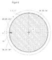
- FIG. 8 shows in the form of an overall view a complete radial section through a printing cylinder 30, 30 ', 30 "according to the invention with a blanket 1, 1', 1" for a web offset printing press.
- An axis A extends centrally in the impression cylinder 30, 30 ', 30 ".
- a channel 34, 34', 34" directed radially inwards is provided parallel to the axis A at the circumference of the impression cylinder 30, 30 " , 34 ', 34 "are two end portions 10, 20, 20', 20" of the fully on the printing cylinder 30, 30 ', 30 "attached blanket 1, 1', 1” introduced, wherein the first end portion 10 in a direction of production P
- the pressure cylinder 30, 30 ', 30 "leading and the second end portion 20, 20', 20” formed trailing.
- Between the end portions 10, 20, 20 ', 20 extends to the end portions 10, 20, 20', 20th “adjacent over almost the entire circumference of the printing cylinder 30, 30 ', 30” a main portion 5 of the blanket 1, 1', 1 ".
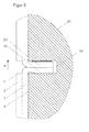
- FIG. 1 A first of the general view according to FIG. 8 detected embodiments is in FIG. 1 shown.
- the channel 34 has a channel depth 36 and a channel thickness 38. With these dimensions, a groove in the lateral surface of the impression cylinder 30 is defined, which receives the end portions 10, 20 of the blanket 1.
- the blanket 1 is multi-ply, d. H. constructed with several layers 2, 3, 4 in the radial direction. Each of the layers has a special function. Not shown are other layers that may be present and well known. Radially inside the printing cylinder 30 facing a self-adhesive layer 4 of the blanket 1 is glued to the printing cylinder 30. Radially outward directed is followed by a carrier layer 3, which is usually formed from a fabric. Radially on the outside, the rubber blanket 1 has a cover layer 2 facing away from the printing cylinder 30. The cover layer 2 fulfills the respective criteria with regard to the surface for producing a perfect print image on the printing material, which is not shown.
- This layer construction is almost over the entire circumference of the blanket 1, i. in its main section 5, completely formed.
- the self-adhesive layer 4 and the carrier layer 3 are removed radially inward.
- the end portions 10, 20 of the blanket 1 are thus introduced in the first embodiment only with a reduced thickness, namely the thickness of the cover layer 2 in the channel 34.
- an insertion aid 7 designed as a strip 9 is introduced into the channel 34 in the radial direction.
- the end portions 10, 20 are clamped by the thickness of the strip 9 in comparison to the channel thickness 38 in the channel 34.
- the end portions 10, 20 are elastically deformed.
- the Insertion aid 7 may also be formed as a one-sided stiffening layer on the respective end portion 10, 20, which consists of metal, plastic or ceramic.
- the success resulting from the arrangement according to the first embodiment is a complete sealing of the self-adhesive layer 4 to the outside.
- the inserted into the channel 34 end portions 10, 20 of the blanket 1 are inserted into the channel 34 around the radially outer edges 11, 21 around, inserted or inserted and additionally fixed by the bar 9 in the channel 34.
- the channel 34 is undersized with respect to the inserted end portions 10, 20 and the ledge 9, so that the end portions 10, 20 are clamped in the channel 34 without the need for further equipment. This results in a secure seal to the outside.
- FIG. 3 represents a third embodiment. Comparable to the representation in FIG. 1 again a section of a radial section of the printing cylinder 30 'is shown with glued blanket 1'. In the pressure cylinder 30 'is comparable to FIG. 1 a channel 34 'with a channel thickness 38' and a channel depth 36 'is formed.
- the blanket 1 ' is also comparable to the representation in FIG. 1 the printing cylinder 30 'facing at the level of the radially outer edges 11, 21 of the channel 34' is cut.
- the self-adhesive layer 4 and the carrier layer 3 are in the second embodiment to the respective end portions 10, 20 'of the blanket 1 'deducted.
- the channel 34 ' is arranged between the trailing end portion 20' of the blanket 1 'and a wall 22 of the channel 34' also designed as a bar 14 insertion aid 7.
- the strip 14 is attached according to a preferred embodiment of the invention at the trailing end portion 20 'and introduced together with this in the channel 34'.
- This arrangement is particularly easy to install, because the leading end portion 10 can initially be introduced without problems in the channel 34 '.
- the trailing end portion 20 'must, in order to achieve a secure seal of the self-adhesive layer 4 against solvents or ink, are pressed into the channel 34', so that there is an elastic deformation of the end portions 10, 20 '.
- the channel 34 ' with respect to the thickness of the end portions 10, 20' and the bar 14 executed with undersize.
- the wall 22 of the channel 34 'or the bar 14 may be provided on the wall 22 side facing with a sliding layer 6.
- This overlay 6 can be applied to the corresponding surfaces in a change of the blanket 1 '.
- the strip 14 or the wall 22 may alternatively or additionally be equipped with durable sliding layers 6.
- Such sliding layers 6 consist for example of polytetrafluoroethylene or other substances with sliding properties.
- the end portions 10, 20 'of the blanket 1' are preferably at least partially made of metal, plastic or ceramic, which may also have sliding properties.
- FIG. 4 shows an enlarged section of a radial section of a printing cylinder 30 "comparable to the impression cylinder 30 'of FIG. 3 in a fourth embodiment.
- a spring element 8 is provided in a channel 34 "between the strip 14 and the wall 22.
- the spring element 8 is itself deformable and causes an elastic deformation of the introduced into the channel 34 "end portions 10, 20 'of the blanket 1'.
- Such spring elements 8 are the skilled person in addition to the in FIG. 4 illustrated embodiment of a curved sheet also known in other forms. For example, as a substitute over the length of the channel 34 "distributed spiral spring elements are conceivable, which can also lead to an elastic deformation of the end portions 10, 20 'of the blanket 1'.
- FIG. 5 shows a detail of a radial section of a fifth embodiment.
- the illustrated printing cylinder 30 ' also has a channel 34' with a channel thickness 38 'and a channel depth 36' in its lateral surface as in the preceding exemplary embodiments.
- a blanket 1 " is attached to the printing cylinder 30 'with a self-adhesive layer 4.
- the main section 5 of the blanket 1" again has the usual layered structure, i.
- a carrier layer 3 and a cover layer 2 are formed.
- the cover layer 2 is removed at the trailing end section 20 "Otherwise, a strip 14 is also provided in this embodiment between the wall 22 of the channel 34 'and the trailing end section 20" of the blanket 1 " the trailing end portion 20 "easier.
- FIG. 6 shows a next embodiment, in which both the leading and the trailing end portion 10, 20 "of the blanket 1", the cover layer 2 is removed.
- FIG. 7 is a further embodiment of a printing cylinder according to the invention 30 '' shown, in comparison to the overview representation according to FIG. 8 deviating executed.
- the difference from the previously described Embodiments consist in the orientation of the channel 34 "'obliquely radially inwardly into the interior of the printing cylinder 30"'.
- Another deviation is the removal of layers of the end portions 10 ', 20 "' inserted into the oblique channel 34" '.
- the self-adhesive layer 4 always ends at the radially outer edge 11, 21 of the channel 34, 34 ', 34 ", 34"' in order to prevent the insertion and removal of the respective end sections 10, 10 ', 20, 20'. 20 “, 20” 'of blanket 1,1', 1 ", 1” 'not to complicate.
Landscapes
- Printing Plates And Materials Therefor (AREA)
- Rotary Presses (AREA)
Priority Applications (5)
| Application Number | Priority Date | Filing Date | Title |
|---|---|---|---|
| EP09160532A EP2253471A1 (fr) | 2009-05-18 | 2009-05-18 | Cylindre de pression doté d'un tissu en caoutchouc pour une presse rotative offset à rouleaux |
| CN2010101834337A CN101890848A (zh) | 2009-05-18 | 2010-05-18 | 用于卷筒纸胶印印刷机的带有像皮布的印刷滚筒 |
| JP2010114287A JP2010264754A (ja) | 2009-05-18 | 2010-05-18 | ローラオフセット印刷機用のゴムブランケットを備えた押付けシリンダ |
| US12/782,334 US20100288147A1 (en) | 2009-05-18 | 2010-05-18 | Print cylinder with rubber blanket for a rotary offset printing press |
| BRPI1001855-7A BRPI1001855A2 (pt) | 2009-05-18 | 2010-05-18 | cilindro de impressão com blanqueta para rotativa offset de bobinas |
Applications Claiming Priority (1)
| Application Number | Priority Date | Filing Date | Title |
|---|---|---|---|
| EP09160532A EP2253471A1 (fr) | 2009-05-18 | 2009-05-18 | Cylindre de pression doté d'un tissu en caoutchouc pour une presse rotative offset à rouleaux |
Publications (1)
| Publication Number | Publication Date |
|---|---|
| EP2253471A1 true EP2253471A1 (fr) | 2010-11-24 |
Family
ID=41090384
Family Applications (1)
| Application Number | Title | Priority Date | Filing Date |
|---|---|---|---|
| EP09160532A Withdrawn EP2253471A1 (fr) | 2009-05-18 | 2009-05-18 | Cylindre de pression doté d'un tissu en caoutchouc pour une presse rotative offset à rouleaux |
Country Status (5)
| Country | Link |
|---|---|
| US (1) | US20100288147A1 (fr) |
| EP (1) | EP2253471A1 (fr) |
| JP (1) | JP2010264754A (fr) |
| CN (1) | CN101890848A (fr) |
| BR (1) | BRPI1001855A2 (fr) |
Cited By (3)
| Publication number | Priority date | Publication date | Assignee | Title |
|---|---|---|---|---|
| DE102010064414A1 (de) * | 2010-12-10 | 2012-09-27 | Manroland Web Systems Gmbh | Drucktuch,Verfahren zum Herstellen desselben und Spanneinrichtung eines Übertragungszylinders für ein Drucktuch |
| DE102011084205A1 (de) * | 2011-10-10 | 2013-04-11 | Koenig & Bauer Aktiengesellschaft | Drucktucheinheit und ein Verfahren zur Herstellung einer Drucktucheinheit |
| NL2020109B1 (en) * | 2017-12-18 | 2019-06-25 | Xeikon Prepress Nv | Method for fixing and treating a flexible plate on a drum, and flexible plate for use therein |
Citations (6)
| Publication number | Priority date | Publication date | Assignee | Title |
|---|---|---|---|---|
| GB2080204A (en) * | 1980-07-25 | 1982-02-03 | Grace W R & Co | Offset printing blanket |
| DE3338127C1 (de) * | 1983-10-20 | 1985-04-04 | M.A.N.- Roland Druckmaschinen AG, 6050 Offenbach | Spannvorrichtung für einen Gummituchzylinder einer Rollenrotationsdruckmaschine |
| JPH0250361U (fr) * | 1988-10-05 | 1990-04-09 | ||
| DE4320464A1 (de) * | 1993-06-21 | 1994-12-22 | Roland Man Druckmasch | Übertragungszylinder für Rotationsdruckmaschinen |
| WO1996011426A1 (fr) * | 1994-10-11 | 1996-04-18 | Indigo N.V. | Appareil de formation d'images et blanchet de transfert intermediaire associe |
| JP2003011325A (ja) * | 2001-07-03 | 2003-01-15 | Miyakoshi Printing Machinery Co Ltd | ブランケット胴装置 |
Family Cites Families (17)
| Publication number | Priority date | Publication date | Assignee | Title |
|---|---|---|---|---|
| US3489085A (en) * | 1967-08-11 | 1970-01-13 | David M Co | Printing blanket edging and anchoring means |
| DE4102858A1 (de) * | 1990-03-08 | 1991-09-12 | Heidelberger Druckmasch Ag | Druckwerkszylinder fuer rotationsdruckmaschinen |
| US5357863A (en) * | 1991-11-15 | 1994-10-25 | Day International, Inc. | Printing blanket for use with a printing cylinder to achieve a narrow gap lock-up |
| DE19543584C1 (de) * | 1995-11-23 | 1997-07-24 | Koenig & Bauer Albert Ag | Gummituch für eine Druckmaschine |
| DE19602746A1 (de) * | 1996-01-26 | 1997-07-31 | Kocher & Beck Gmbh & Co Rotati | Druckzylinder für ein Klischee aus magnetisierbarem Trägermaterial |
| US5749298A (en) * | 1997-06-10 | 1998-05-12 | Reeves Brothers, Inc. | Arrangement for securing a printing blanket to a cylinder |
| FR2764842B1 (fr) * | 1997-06-24 | 1999-09-24 | Jean Francille | Dispositif de guidage integre pour manchon ou cylindre d'impression et manchon ou cylindre equipe de ce dispositif |
| DE19844560C2 (de) * | 1998-09-29 | 2001-05-17 | Roland Man Druckmasch | Vorrichtung und Verfahren zum Befestigen einer flexiblen Druckform |
| US6131513A (en) * | 1998-10-23 | 2000-10-17 | Heidelberger Druckmaschinen Ag | Printing press with simple lock-up plate cylinder |
| US6397746B1 (en) * | 1999-08-09 | 2002-06-04 | Fuji Photo Film Co., Ltd. | Camera-ready copy sheet for lithographic printing plates |
| US6378430B1 (en) * | 1999-10-15 | 2002-04-30 | King Press Corporation | Cylinder with plate gripping device |
| EP1127687B1 (fr) * | 2000-02-21 | 2011-04-13 | FUJIFILM Corporation | Elément de montage, procédé et appareil pour le montage de plaques d'impression flexibles |
| JP3681685B2 (ja) * | 2000-03-21 | 2005-08-10 | デイ インターナショナル インコーポレーテッド | 非伸長性裏打ち体を備えた可撓性を有する画像転写ブランケット |
| JP2003145715A (ja) * | 2001-11-07 | 2003-05-21 | Fuji Photo Film Co Ltd | 可撓性刷版装着方法および装着装置 |
| US6912955B2 (en) * | 2003-08-21 | 2005-07-05 | Reeves Brothers, Inc. | Metal-backed printing blanket |
| DE102004034049A1 (de) * | 2004-07-13 | 2006-02-09 | Man Roland Druckmaschinen Ag | Formzylinder einer Rollenrotationsdruckmaschine |
| EP1957270B1 (fr) * | 2005-10-17 | 2015-04-15 | Gerald J. Gartner | Procede pour monter une plaque sur un element adhesif |
-
2009
- 2009-05-18 EP EP09160532A patent/EP2253471A1/fr not_active Withdrawn
-
2010
- 2010-05-18 BR BRPI1001855-7A patent/BRPI1001855A2/pt not_active Application Discontinuation
- 2010-05-18 CN CN2010101834337A patent/CN101890848A/zh active Pending
- 2010-05-18 JP JP2010114287A patent/JP2010264754A/ja active Pending
- 2010-05-18 US US12/782,334 patent/US20100288147A1/en not_active Abandoned
Patent Citations (6)
| Publication number | Priority date | Publication date | Assignee | Title |
|---|---|---|---|---|
| GB2080204A (en) * | 1980-07-25 | 1982-02-03 | Grace W R & Co | Offset printing blanket |
| DE3338127C1 (de) * | 1983-10-20 | 1985-04-04 | M.A.N.- Roland Druckmaschinen AG, 6050 Offenbach | Spannvorrichtung für einen Gummituchzylinder einer Rollenrotationsdruckmaschine |
| JPH0250361U (fr) * | 1988-10-05 | 1990-04-09 | ||
| DE4320464A1 (de) * | 1993-06-21 | 1994-12-22 | Roland Man Druckmasch | Übertragungszylinder für Rotationsdruckmaschinen |
| WO1996011426A1 (fr) * | 1994-10-11 | 1996-04-18 | Indigo N.V. | Appareil de formation d'images et blanchet de transfert intermediaire associe |
| JP2003011325A (ja) * | 2001-07-03 | 2003-01-15 | Miyakoshi Printing Machinery Co Ltd | ブランケット胴装置 |
Cited By (6)
| Publication number | Priority date | Publication date | Assignee | Title |
|---|---|---|---|---|
| DE102010064414A1 (de) * | 2010-12-10 | 2012-09-27 | Manroland Web Systems Gmbh | Drucktuch,Verfahren zum Herstellen desselben und Spanneinrichtung eines Übertragungszylinders für ein Drucktuch |
| DE102011084205A1 (de) * | 2011-10-10 | 2013-04-11 | Koenig & Bauer Aktiengesellschaft | Drucktucheinheit und ein Verfahren zur Herstellung einer Drucktucheinheit |
| DE102011084205B4 (de) | 2011-10-10 | 2022-12-08 | Koenig & Bauer Ag | Verfahren zur Herstellung einer Drucktucheinheit |
| NL2020109B1 (en) * | 2017-12-18 | 2019-06-25 | Xeikon Prepress Nv | Method for fixing and treating a flexible plate on a drum, and flexible plate for use therein |
| WO2019121605A1 (fr) * | 2017-12-18 | 2019-06-27 | Xeikon Prepress N.V. | Procédé de fixation et de traitement d'une plaque souple sur un tambour, et plaque souple |
| US11535028B2 (en) | 2017-12-18 | 2022-12-27 | Xeikon Prepress N.V. | Method for fixing and treating a flexible plate on a drum and flexible plate |
Also Published As
| Publication number | Publication date |
|---|---|
| CN101890848A (zh) | 2010-11-24 |
| US20100288147A1 (en) | 2010-11-18 |
| BRPI1001855A2 (pt) | 2012-01-24 |
| JP2010264754A (ja) | 2010-11-25 |
Similar Documents
| Publication | Publication Date | Title |
|---|---|---|
| DE69504889T2 (de) | Zylinder mit Drucktuch | |
| DE3140122C2 (de) | Mehrschichtiges Drucktuch und Verfahren zu dessen Herstellung | |
| EP0317656B1 (fr) | Cylindre d'unité d'impression comportant une couche de caoutchouc pour l'impression offset, flexographique, en creux, typographique | |
| AT523110A1 (de) | Anschlussprofilleiste | |
| DE2545124B2 (de) | Vorrichtung zum Aufspannen von biegsamen Druckplatten auf dem Formzylinder von Rotations-Tiefdruckmaschinen | |
| EP2253471A1 (fr) | Cylindre de pression doté d'un tissu en caoutchouc pour une presse rotative offset à rouleaux | |
| DE4428670B4 (de) | Rotations-Siebdruckzylinder | |
| EP1591271B1 (fr) | Blanchet de transfert en particulier blanchet en caoutchouc, pour machine d'impression | |
| EP1572461B1 (fr) | Ensemble blanchet pour cylindre a blanchet et son procede de production | |
| EP1659216A1 (fr) | Rouleau pour la production d'un matériau en bande, en particulier pour l'essorage de matière cellulosique | |
| EP1543988B1 (fr) | Blanchet d'impression avec support en métal ou plastique | |
| EP3206876B1 (fr) | Manchon d'impression et procédé de fabrication d'une manchon d'impression | |
| EP3311060B1 (fr) | Support de tube | |
| EP3462073A1 (fr) | Raccordement d'une dérivation | |
| DE19924785A1 (de) | Vorrichtung zum Befestigen von biegsamen Platten | |
| EP1543987B1 (fr) | Blanchet d'impression ayant une plaque support rigide et élastique | |
| DE102013103712A1 (de) | Druckwerk und Gummituchplatte für ein Druckwerk | |
| DE10115877A1 (de) | Druckwerkszylinder | |
| DE102010015108A1 (de) | Rotationszylinder für eine Verarbeitungsmaschine | |
| DE10023988B4 (de) | Aufzug eines Formzylinders einer Rotations-Hochdruckmaschine | |
| EP1264627A1 (fr) | Tissu filtrant pour un dispositif de filtration et méthode de montage d' un tissu filtrant | |
| DE102006027143B4 (de) | Drucktucheinheit für einen Drucktuchzylinder einer Rotationsdruckmaschine | |
| DE102006027144B3 (de) | Drucktucheinheit für einen Drucktuchzylinder einer Rotationsdruckmaschine | |
| EP1705390B1 (fr) | Fixation et étanchéité d'un bandage de cylindre avec des anneaux de serrage sur les disques d'extrémité d'un dispositif de formation d'une fente longitudinale | |
| DE102004001398B4 (de) | Verfahren zur Herstellung einer Öffnung an der Mantelfläche eines Zylinders einer Druckmaschine und Zylinder |
Legal Events
| Date | Code | Title | Description |
|---|---|---|---|
| PUAI | Public reference made under article 153(3) epc to a published international application that has entered the european phase |
Free format text: ORIGINAL CODE: 0009012 |
|
| AK | Designated contracting states |
Kind code of ref document: A1 Designated state(s): AT BE BG CH CY CZ DE DK EE ES FI FR GB GR HR HU IE IS IT LI LT LU LV MC MK MT NL NO PL PT RO SE SI SK TR |
|
| 17P | Request for examination filed |
Effective date: 20110215 |
|
| 17Q | First examination report despatched |
Effective date: 20110330 |
|
| STAA | Information on the status of an ep patent application or granted ep patent |
Free format text: STATUS: THE APPLICATION IS DEEMED TO BE WITHDRAWN |
|
| 18D | Application deemed to be withdrawn |
Effective date: 20111011 |