EP2255121B1 - Conduit d'air en tissu longitudinalement fondu - Google Patents
Conduit d'air en tissu longitudinalement fondu Download PDFInfo
- Publication number
- EP2255121B1 EP2255121B1 EP09717210.0A EP09717210A EP2255121B1 EP 2255121 B1 EP2255121 B1 EP 2255121B1 EP 09717210 A EP09717210 A EP 09717210A EP 2255121 B1 EP2255121 B1 EP 2255121B1
- Authority
- EP
- European Patent Office
- Prior art keywords
- sheet
- air duct
- upper sheet
- lower sheet
- air
- Prior art date
- Legal status (The legal status is an assumption and is not a legal conclusion. Google has not performed a legal analysis and makes no representation as to the accuracy of the status listed.)
- Active
Links
Images


Classifications
-
- F—MECHANICAL ENGINEERING; LIGHTING; HEATING; WEAPONS; BLASTING
- F24—HEATING; RANGES; VENTILATING
- F24F—AIR-CONDITIONING; AIR-HUMIDIFICATION; VENTILATION; USE OF AIR CURRENTS FOR SCREENING
- F24F13/00—Details common to, or for air-conditioning, air-humidification, ventilation or use of air currents for screening
- F24F13/02—Ducting arrangements
- F24F13/0209—Ducting arrangements characterised by their connecting means, e.g. flanges
-
- F—MECHANICAL ENGINEERING; LIGHTING; HEATING; WEAPONS; BLASTING
- F16—ENGINEERING ELEMENTS AND UNITS; GENERAL MEASURES FOR PRODUCING AND MAINTAINING EFFECTIVE FUNCTIONING OF MACHINES OR INSTALLATIONS; THERMAL INSULATION IN GENERAL
- F16L—PIPES; JOINTS OR FITTINGS FOR PIPES; SUPPORTS FOR PIPES, CABLES OR PROTECTIVE TUBING; MEANS FOR THERMAL INSULATION IN GENERAL
- F16L11/00—Hoses, i.e. flexible pipes
- F16L11/02—Hoses, i.e. flexible pipes made of fibres or threads, e.g. of textile
-
- F—MECHANICAL ENGINEERING; LIGHTING; HEATING; WEAPONS; BLASTING
- F16—ENGINEERING ELEMENTS AND UNITS; GENERAL MEASURES FOR PRODUCING AND MAINTAINING EFFECTIVE FUNCTIONING OF MACHINES OR INSTALLATIONS; THERMAL INSULATION IN GENERAL
- F16L—PIPES; JOINTS OR FITTINGS FOR PIPES; SUPPORTS FOR PIPES, CABLES OR PROTECTIVE TUBING; MEANS FOR THERMAL INSULATION IN GENERAL
- F16L31/00—Arrangements for connecting hoses to one another or to flexible sleeves
- F16L31/02—Arrangements for connecting hoses to one another or to flexible sleeves for branching hoses
-
- F—MECHANICAL ENGINEERING; LIGHTING; HEATING; WEAPONS; BLASTING
- F24—HEATING; RANGES; VENTILATING
- F24F—AIR-CONDITIONING; AIR-HUMIDIFICATION; VENTILATION; USE OF AIR CURRENTS FOR SCREENING
- F24F13/00—Details common to, or for air-conditioning, air-humidification, ventilation or use of air currents for screening
- F24F13/02—Ducting arrangements
- F24F13/0218—Flexible soft ducts, e.g. ducts made of permeable textiles
-
- F—MECHANICAL ENGINEERING; LIGHTING; HEATING; WEAPONS; BLASTING
- F24—HEATING; RANGES; VENTILATING
- F24F—AIR-CONDITIONING; AIR-HUMIDIFICATION; VENTILATION; USE OF AIR CURRENTS FOR SCREENING
- F24F13/00—Details common to, or for air-conditioning, air-humidification, ventilation or use of air currents for screening
- F24F13/02—Ducting arrangements
- F24F13/06—Outlets for directing or distributing air into rooms or spaces, e.g. ceiling air diffuser
- F24F13/068—Outlets for directing or distributing air into rooms or spaces, e.g. ceiling air diffuser formed as perforated walls, ceilings or floors
-
- F—MECHANICAL ENGINEERING; LIGHTING; HEATING; WEAPONS; BLASTING
- F24—HEATING; RANGES; VENTILATING
- F24F—AIR-CONDITIONING; AIR-HUMIDIFICATION; VENTILATION; USE OF AIR CURRENTS FOR SCREENING
- F24F13/00—Details common to, or for air-conditioning, air-humidification, ventilation or use of air currents for screening
- F24F13/02—Ducting arrangements
- F24F13/06—Outlets for directing or distributing air into rooms or spaces, e.g. ceiling air diffuser
- F24F2013/0608—Perforated ducts
Definitions
- the subject disclosure generally pertains to air ducts and more specifically to fabric air ducts.
- Fabric air ducts are often preferred over sheet metal ones for various reasons. Fabric ducts can evenly distribute the air, can be less prone to surface condensation, have a nice appearance, are lightweight, and are usually removable for periodic cleaning. Fabric ducts, nonetheless, do have some drawbacks.
- Fabric ducts can sometimes be difficult to remove and attach to a main supply air duct.
- the point of attachment is at a location with limited accessibility, particularly if the main supply air duct is directly above the fabric duct.
- U.S. Patent 6,280,320 discloses a flexible air duct for conveying and distributing a source of forced air to a room or other area of a building.
- the air duct includes a flexible outer casing made of an air permeable fabric that evenly disperses the air into the room.
- a support frame holds the casing in a generally open tubular shape even when the duct's interior and exterior air pressures are the same.
- the air duct can be connected at one end to a side surface of an inlet duct with a zipper.
- an air duct made of a fabric that is more air permeable in some areas than others. For example, there might be a need for more airflow below the duct than above it. This could be accomplished by joining fabrics of different permeability; however, sewing together different materials does not always work well.
- the present invention provides an air duct assembly for connection to a vertically extending inlet duct, in accordance with the subject-matter of independent claim 1.
- FIGS. 1 - 3 show an air duct assembly 10 suspended below a ceiling 12 of a building and connected to a vertically extending inlet air duct 14.
- a blower 15 forces air 16 through duct 14 and through a horizontally extending air passageway 18 that is between an upper sheet 20 and a lower sheet 22 of duct assembly 10.
- Outlet openings or the air permeability of at least one of sheets 20 and 22 can disperse the air into various rooms or areas within the building.
- Sheets 20 and 22 are each made of a pliable material (e.g., an air permeable or impermeable fabric) that can be removed from its supporting structure for cleaning (e.g., in a washing machine). Sheets 20 and 22 can be made of the same or different materials to provide air duct assembly 10 with certain airflow characteristics or other desirable properties such as appearance, strength, and different or identical air permeability.
- a pliable material e.g., an air permeable or impermeable fabric
- Sheets 20 and 22 can be made of the same or different materials to provide air duct assembly 10 with certain airflow characteristics or other desirable properties such as appearance, strength, and different or identical air permeability.
- the sheets 20 and 22 can be supported by two tracks 24, each of which define a first channel 26 and a second channel 28.
- a pair of elongate beads 30 on upper sheet 20 can be slid lengthwise into first channel 26.
- a pair of elongate beads 32 on lower sheet 22 can be slid into second channel 28.
- the upper sheet 20 and/or the lower sheet 22 may be supported by any other suitable method. Before completely installing lower sheet 22, however, it may be more convenient to first connect upper sheet 20 to inlet duct 14, otherwise lower sheet 22 may obstruct access to inlet duct 14.
- a first separable joint 34 can be used for connecting inlet duct 14 in fluid communication with an inlet opening 36 defined by upper sheet 20.
- An arrow 38 represents the step of removably coupling upper sheet 20 to inlet duct 14.
- joint 34 includes a pliable tube 40 that is fastened via a clamp 42 or otherwise attached to inlet duct 14, and a pliable fastener 44 removably connects tube 40 to the perimeter of opening 36.
- pliable fastener 44 include, but are not limited to, a zipper or a hook-and-loop fastener such a VELCRO fastener, wherein VELCRO is a registered trademark of Velcro Industries of Manchester, NH.
- a first pliable end panel 48 ( FIG. 1 ) and a second pliable end panel 50 can be installed to prevent air 16 from blowing freely out the ends of duct assembly 10.
- Panels 48 and 50 can be permeable or impermeable to air.
- Panels 48 and 50 can also be completely separate items or they can be an integral extension of upper sheet 20 or lower sheet 22.
- End panel 48 is an example of a completely separate item fastened to sheets 20 and 22 by way of a zipper 52 and a hook-and-loop fastener 54, respectively.
- End panel 50 is an integral extension of upper sheet 20, while zipper 52 removably fastens panel 50 to lower sheet 22.
- the panels 48 and/or 50 may be removably coupled to the lower sheet 20 and/or the upper sheet 22 by any suitable method.
- a separable joint 56 can also provide a convenient location for adding an airflow modifier 58.
- airflow modifier 58 include, but are not limited to, a filter, airflow turning vane, noise attenuator, etc.
- Airflow modifier 58 can be attached using any suitable fastener including, but not limited to, a zipper, hook-and-loop fastener, etc.
- an air duct assembly 60 of FIGS. 6 and 7 shows an upper sheet 62 supported by a pair of single-channel tracks 64.
- Upper sheet 62 includes two strips of material 66 with a pliable fastener 68 (e.g., zipper or hook-and-loop) that removably connects to a lower sheet 70.
- a pliable fastener 68 e.g., zipper or hook-and-loop
- the structure and function of air duct assembly 60 can otherwise be similar to that of duct assembly 10.
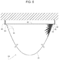
- FIG. 5A includes a fabric member 80 positioned across the inlet duct 14 to modify airflow and/or air pressure to minimize flutter.
- a pair of elongate beads 82 are slid into second channel 28.
- elongate beads 82 of fabric member 80 and lower sheet 22 are the same.
- fabric member 80 may be supported using any suitable method and tracks 24 may include any number of channels (3, 4, etc.).
- additional fabric members 80 may be included (e.g., 2, 3, 4, etc.) that are positioned at a distance from one another.
- Fabric member 80 may include a single layer of pliable material (e.g., an air permeable or impermeable fabric) or a plurality of layers of pliable material.
- the fabric member 80 may include any number (e.g., 1, 2, 3, etc.) of areas (e.g., sections) that may be made of the same or different materials that have similar or different characteristics, such as, for example, strength, and/or air permeability. Additionally, the different areas may be the same or different sizes.
- the fabric member 80 may include areas of varying porosity such as, for example, an area that is a first porosity and an area that is a second porosity.
- an air duct assembly includes upper and lower pliable sheets that are joined longitudinally to make it easier to attach the upper sheet to a vertical main supply air duct made of relatively rigid sheet metal.
- upper and lower pliable sheets are suspended from separate track channels so that the sheets can be installed individually.
- an air duct assembly includes separate upper and lower sheets that are sufficiently pliable to machine-wash them individually.
- a single track member includes two channels to support two individual pliable sheets.
- an air duct assembly includes upper and lower sheets plus two pliable end panels that are joined to the sheets by way of at least one pliable fastener.
- an air duct assembly includes upper and lower pliable sheets, wherein one sheet is more air permeable than the other.
- an air duct assembly comprising two pliable sheets includes a removable airflow modifier that is coupled to a main supply air duct that delivers air to a passageway between the two sheets.
- a removable airflow modifier includes, but is not limited to, a filter, airflow-turning vane or noise attenuator.
- an air duct assembly includes upper and lower sheets which can be installed by installing the lower sheet after the upper sheet is attached to a main supply air duct.
Landscapes
- Engineering & Computer Science (AREA)
- General Engineering & Computer Science (AREA)
- Mechanical Engineering (AREA)
- Chemical & Material Sciences (AREA)
- Combustion & Propulsion (AREA)
- Textile Engineering (AREA)
- Duct Arrangements (AREA)
- Tents Or Canopies (AREA)
Claims (7)
- Ensemble conduit d'air pour raccordement à un conduit d'entrée s'étendant verticalement (14), l'ensemble conduit d'air comprenant :une feuille supérieure (20) comprenant un premier matériau pliable, la feuille supérieure (20) définissant une ouverture d'entrée (36) avec un premier joint séparable (34) pour raccorder la feuille supérieure (20) au conduit d'entrée s'étendant verticalement (14) afin de placer le conduit d'entrée s'étendant verticalement (14) en communication fluidique avec l'ouverture d'entrée (36) de la feuille supérieure (20) ;une feuille inférieure (22) comprenant un deuxième matériau pliable ;un deuxième joint séparable (24) accouplant la feuille supérieure (20) à la feuille inférieure (22) ; etun troisième joint séparable (24) accouplant la feuille supérieure (20) à la feuille inférieure (22), le deuxième joint séparable (24) et le troisième joint séparable (24) étant espacés l'un de l'autre avec la feuille supérieure (20) et la feuille inférieure (22) s'étendant entre eux, la feuille supérieure (20) et la feuille inférieure (22) définissant un passage d'air s'étendant horizontalement entre elles quand la feuille supérieure (20) est accouplée à la feuille inférieure (22) ;dans lequel les deuxième et troisième joints séparables (24) incluent tous les deux une piste définissant un premier canal (26) et un deuxième canal (28), dans lequel la feuille supérieure (20) entre en prise de manière complémentaire avec le premier canal (26), et la feuille inférieure (22) entre en prise de manière complémentaire avec le deuxième canal (28).
- Ensemble conduit d'air selon la revendication 1, comprenant en outre :un premier panneau d'extrémité pliable (48) s'étendant entre la feuille supérieure (20) et la feuille inférieure (22) ; etun quatrième joint séparable (52, 54) accouplant le premier panneau d'extrémité pliable (48) à au moins l'une de la feuille supérieure (20) et de la feuille inférieure (22).
- Ensemble conduit d'air selon la revendication 2, comprenant en outre :un deuxième panneau d'extrémité pliable (50) s'étendant entre la feuille supérieure (20) et la feuille inférieure (22), dans lequel l'ouverture d'entrée (36) est entre le premier panneau d'extrémité pliable (48) et le deuxième panneau d'extrémité pliable (50) ; etun cinquième joint séparable (52) accouplant le deuxième panneau d'extrémité pliable (50) à au moins l'une de la feuille supérieure (20) et de la feuille inférieure (22).
- Ensemble conduit d'air selon la revendication 1, dans lequel la feuille supérieure (20) et la feuille inférieure (22) présentent des niveaux de perméabilité à l'air différents.
- Ensemble conduit d'air selon la revendication 1, comprenant en outre un modificateur d'écoulement d'air raccordé au premier joint séparable (34).
- Ensemble conduit d'air selon la revendication 1, comprenant en outre élément perméable situé à travers l'entrée afin de modifier un écoulement d'air ou une pression d'air afin de minimiser le flottement de la feuille inférieure (22).
- Ensemble conduit d'air selon la revendication 6, dans lequel l'élément perméable présente une première zone d'une première porosité et une deuxième zone d'une deuxième porosité.
Applications Claiming Priority (2)
| Application Number | Priority Date | Filing Date | Title |
|---|---|---|---|
| US12/040,614 US9039503B2 (en) | 2008-02-29 | 2008-02-29 | Longitudinally split fabric air duct |
| PCT/US2009/035159 WO2009111246A1 (fr) | 2008-02-29 | 2009-02-25 | Conduit d'air en tissu longitudinalement fondu |
Publications (2)
| Publication Number | Publication Date |
|---|---|
| EP2255121A1 EP2255121A1 (fr) | 2010-12-01 |
| EP2255121B1 true EP2255121B1 (fr) | 2018-01-17 |
Family
ID=40678404
Family Applications (1)
| Application Number | Title | Priority Date | Filing Date |
|---|---|---|---|
| EP09717210.0A Active EP2255121B1 (fr) | 2008-02-29 | 2009-02-25 | Conduit d'air en tissu longitudinalement fondu |
Country Status (8)
| Country | Link |
|---|---|
| US (1) | US9039503B2 (fr) |
| EP (1) | EP2255121B1 (fr) |
| CN (1) | CN101960201A (fr) |
| AU (1) | AU2009222205B2 (fr) |
| CA (1) | CA2716126C (fr) |
| DK (1) | DK2255121T3 (fr) |
| LT (1) | LT2255121T (fr) |
| WO (1) | WO2009111246A1 (fr) |
Families Citing this family (15)
| Publication number | Priority date | Publication date | Assignee | Title |
|---|---|---|---|---|
| LT2354696T (lt) * | 2010-01-22 | 2017-01-25 | Ke Fibertec A/S | Kryptinio srauto valdomas ortakis |
| DE202010017538U1 (de) * | 2010-01-29 | 2012-02-29 | H. Lüdi + Co. Ag | Mediendecke mit einem flexiblen Zuluftkanal |
| US9494336B2 (en) * | 2010-05-03 | 2016-11-15 | Rite-Hite Holding Corporation | Configurable pliable air ducts |
| US9631825B2 (en) | 2012-12-18 | 2017-04-25 | Nortek Air Solutions, Llc | Air filter assembly |
| US9512555B2 (en) | 2014-12-31 | 2016-12-06 | Barry J. Garner | Expandable exhaust duct assembly |
| US12196444B2 (en) * | 2015-06-25 | 2025-01-14 | Leiterman And Associates, Inc. | Air duct systems and methods of air flow control |
| US11512868B2 (en) * | 2015-06-25 | 2022-11-29 | Leiterman & Associates, Inc. | Air duct systems and methods of air flow control |
| US9599362B2 (en) * | 2015-06-25 | 2017-03-21 | Leiterman And Associates, Inc. | Air duct systems and methods of air flow control |
| US11293663B2 (en) * | 2017-01-26 | 2022-04-05 | Rite-Hite Holding Corporation | Fabric drop-down diffusers |
| US11231202B2 (en) * | 2017-01-26 | 2022-01-25 | Rite-Hite Holding Corporation | Fabric drop-down diffusers |
| CN107620840A (zh) * | 2017-11-01 | 2018-01-23 | 罗熙果 | 组合式通水用布胶水管 |
| AU2019355930B2 (en) | 2018-10-02 | 2022-06-09 | Rite-Hite Holding Corporation | Air barrier systems for data center zone containment |
| WO2020096966A1 (fr) * | 2018-11-09 | 2020-05-14 | Rite-Hite Holding Corporation | Diffuseurs déroulants en tissu |
| DE102020006967A1 (de) * | 2020-11-13 | 2022-05-19 | Truma Gerätetechnik GmbH & Co. KG | Tragbares Klimagerät |
| US12487004B2 (en) | 2022-11-23 | 2025-12-02 | Nti Global | Interchangeable duct seal |
Family Cites Families (49)
| Publication number | Priority date | Publication date | Assignee | Title |
|---|---|---|---|---|
| US2423241A (en) | 1943-06-05 | 1947-07-01 | Anemostat Corp America | Air distributing duct, including a damper means |
| US3204391A (en) * | 1962-12-28 | 1965-09-07 | Schwab Louis | Air filtration |
| US3195296A (en) | 1963-01-18 | 1965-07-20 | Hoyt Mfg Corp | Lint filter bag |
| US3357088A (en) | 1964-10-02 | 1967-12-12 | Whirlpool Co | Method of attaching a hanger to an elongated flexible tube wall |
| US3607341A (en) | 1969-11-28 | 1971-09-21 | Gaf Corp | Process for producing a coated substrate |
| FR2185178A5 (fr) | 1972-05-19 | 1973-12-28 | Rhone Poulenc Sa | |
| US3875623A (en) * | 1972-11-21 | 1975-04-08 | Gourock Ropework Co Ltd | Fabric joints |
| US4017282A (en) | 1973-06-18 | 1977-04-12 | Zahka Joseph G | Rain retardant screen |
| SE378978B (fr) | 1974-04-11 | 1975-09-22 | Platmanufaktur Ab | |
| US4159674A (en) * | 1977-04-26 | 1979-07-03 | Brumleu Jr Edward C | Universal diffuser assembly and method of manufacturing |
| DE2912129C2 (de) | 1979-03-28 | 1986-06-12 | Karl Otto Braun Kg, 6759 Wolfstein | Verfahren zur Herstellung einer kohäsiven, starren oder elastischen Binde für Fixierverbände, Kompressions- und Stützverbände und dauerelastische Kompressions- und Stützverbände für medizinische Zwecke |
| US4463483A (en) | 1982-03-11 | 1984-08-07 | W. H. Company, Inc. | Fabric napping apparatus |
| FR2570168B1 (fr) | 1984-09-10 | 1988-11-10 | Ameliorair Sa | Gaine de distribution de gaz dans une enceinte, notamment de distribution d'air dans un local |
| DE8516329U1 (de) | 1985-06-04 | 1985-07-25 | Krebs, Jörg-Peter, 4130 Moers | Luftverteiler für Lüftungs- und Klimaanlagen |
| JPS633143A (ja) | 1986-06-21 | 1988-01-08 | Chizuko Ozawa | 漏風ダクト |
| FI78548C (fi) | 1986-12-30 | 1989-08-10 | Halton Oy | Luftfoerdelningssystem. |
| US4951366A (en) | 1989-02-07 | 1990-08-28 | Geller George R | Method for modifying fabrics to produce varied effects |
| US5024877A (en) | 1989-04-14 | 1991-06-18 | The Dow Chemical Company | Fire resistant materials |
| JPH03110342A (ja) | 1989-09-20 | 1991-05-10 | Mitsubishi Rayon Eng Co Ltd | 気体吹き出しダクト |
| US5111739A (en) * | 1989-11-13 | 1992-05-12 | Hall James F | Air flow control system |
| US5095942A (en) | 1990-02-14 | 1992-03-17 | Murphy Gerard C | Plastic self-insulating ductwork system |
| US5123595A (en) | 1990-03-29 | 1992-06-23 | Doss James R | Method and apparatus for heating and ventilating a poultry house |
| SE500707C2 (sv) * | 1990-08-22 | 1994-08-15 | Jk Vvs Projektering Ab | Tilluftdon med halvsfärisk utströmningsdel uppvisande poröst material |
| FI921156A7 (fi) | 1991-03-20 | 1992-09-21 | Dainippon Ink And Chemicals Inc | Paisuva, tulenkestävä päällyste, tulenkestävä materiaali ja menetelmä tulenkestävän materiaalin valmistamiseksi |
| DK12792D0 (da) | 1992-02-03 | 1992-02-03 | Ke Safematic As | Ventilationssystem |
| JPH0694295A (ja) | 1992-09-10 | 1994-04-05 | Taikisha Ltd | ダクト装置 |
| US5368341A (en) | 1992-10-29 | 1994-11-29 | Larson; L. Robert | Pre-conditioned air hose assembly for aircraft |
| FR2713317B1 (fr) | 1993-12-02 | 1996-02-23 | Grimaud Freres | Installation de diffusion d'air pour bâtiment d'élevage, notamment. |
| JP3458244B2 (ja) | 1993-12-15 | 2003-10-20 | オーケー器材株式会社 | 結露防止型吹出口 |
| US5697282A (en) | 1994-03-15 | 1997-12-16 | Schuller International, Inc. | Apparatus for and method of forming large diameter duct with liner and the product formed thereby |
| US5655963A (en) | 1995-12-04 | 1997-08-12 | Rite-Hite Corporation | Air-releasing endcap for fabric air dispersion system |
| US5782689A (en) * | 1996-01-11 | 1998-07-21 | Tomkins Industries Inc. | Fabric faced air distribution device |
| US5725427A (en) | 1996-01-24 | 1998-03-10 | Chemfab Corporation | Fabric air diffuser, method for diffusing air, and method for attenuating noise associated with flowing air |
| US6002333A (en) | 1996-03-06 | 1999-12-14 | Hickey; Mark J. | Alarm system to assist in gauging the size of a door opening |
| FR2748048B1 (fr) | 1996-04-25 | 1998-07-31 | Air Strategie | Gaine textile pour la protection rapprochee du convoyage de produits sensibles et hotte a flux laminaire comportant une telle gaine |
| US5769708A (en) | 1996-10-22 | 1998-06-23 | Rite-Hite Corporation | Fabric air dispersion system with air dispersing panels |
| GB9622455D0 (en) | 1996-10-29 | 1997-01-08 | Heathcoat & Co Ltd | Gas delivery device |
| US5996281A (en) | 1996-10-31 | 1999-12-07 | Optex Co., Ltd. | Safety auxiliary apparatus for automatic door assembly |
| FR2759153B1 (fr) | 1997-01-31 | 1999-04-16 | Diffusion Thermique Ouest Sa | Systeme de diffusion d'air notamment pour le chauffage, le rafraichissement, l'humidification ou la ventilation d'un local |
| EP0899519B1 (fr) | 1997-07-24 | 2000-05-17 | Marco Zambolin | Conduit de transport et de distribution d'air |
| US5961044A (en) | 1997-07-31 | 1999-10-05 | Rite-Hite Holding Corporation | Misting apparatus and method |
| US6280320B1 (en) * | 1999-07-13 | 2001-08-28 | Rite-Hite Holding Corporation | Frame to support a deflated fabric air duct |
| NL1013242C2 (nl) | 1999-10-08 | 2001-04-23 | Joule Venture Holding B V | Luchtkanaal. |
| DE20000418U1 (de) | 2000-01-12 | 2000-05-04 | Wilhelmi Werke AG, 35633 Lahnau | Klimaelement zum Heizen und/oder Kühlen eines Raumes |
| US6419576B1 (en) * | 2001-03-22 | 2002-07-16 | Air Handling Engineering Ltd. | Sound attenuating inlet silencer for air supplying fan |
| US20020155805A1 (en) | 2001-04-18 | 2002-10-24 | Paschke Nicolas B. | Illuminated fabric air duct |
| US6626754B2 (en) | 2001-07-27 | 2003-09-30 | Rite-Hite Holding Corporation | Conical air filter |
| US6565430B2 (en) | 2001-09-13 | 2003-05-20 | Rite-Hite Holding Corporation | Pliable air duct with dust and condensation repellency |
| SE526035C2 (sv) * | 2002-09-04 | 2005-06-21 | Johnson Medical Dev Pte Ltd | System, anordning och metod för ventilation |
-
2008
- 2008-02-29 US US12/040,614 patent/US9039503B2/en active Active
-
2009
- 2009-02-25 CA CA2716126A patent/CA2716126C/fr active Active
- 2009-02-25 CN CN200980106541XA patent/CN101960201A/zh active Pending
- 2009-02-25 EP EP09717210.0A patent/EP2255121B1/fr active Active
- 2009-02-25 AU AU2009222205A patent/AU2009222205B2/en active Active
- 2009-02-25 DK DK09717210.0T patent/DK2255121T3/en active
- 2009-02-25 LT LTEP09717210.0T patent/LT2255121T/lt unknown
- 2009-02-25 WO PCT/US2009/035159 patent/WO2009111246A1/fr not_active Ceased
Also Published As
| Publication number | Publication date |
|---|---|
| AU2009222205B2 (en) | 2013-05-16 |
| CN101960201A (zh) | 2011-01-26 |
| DK2255121T3 (en) | 2018-04-30 |
| WO2009111246A1 (fr) | 2009-09-11 |
| US20090221226A1 (en) | 2009-09-03 |
| AU2009222205A1 (en) | 2009-09-11 |
| CA2716126A1 (fr) | 2009-09-11 |
| LT2255121T (lt) | 2018-05-25 |
| EP2255121A1 (fr) | 2010-12-01 |
| CA2716126C (fr) | 2013-10-01 |
| US9039503B2 (en) | 2015-05-26 |
Similar Documents
| Publication | Publication Date | Title |
|---|---|---|
| EP2255121B1 (fr) | Conduit d'air en tissu longitudinalement fondu | |
| US12372256B2 (en) | Under-floor pliable air duct/dispersion systems | |
| CA2426778C (fr) | Systeme et procede de limitation d'ecoulement dans une gaine en toile | |
| CA2459722C (fr) | Conduit d'air pliable et resistance a la condensation | |
| US9494336B2 (en) | Configurable pliable air ducts | |
| TWI725009B (zh) | 含橋接細絲的可適形起褶襉空氣過濾器、用於過濾空氣之套組及總成以及過濾空氣之方法 | |
| US8844578B2 (en) | Pliable-wall air ducts with internal expanding structures | |
| JP6363145B2 (ja) | 栽培設備 | |
| CN106461262A (zh) | 向外拉伸的柔顺性空气管道 | |
| US20060070521A1 (en) | Removable duct liner | |
| CN212339433U (zh) | 一种室内风口结构 | |
| WO2020096966A1 (fr) | Diffuseurs déroulants en tissu | |
| JPH08200787A (ja) | 天井冷暖房システムの通気性天井材の構造及び通気性天井材の取り付け構造 | |
| AU2014203662B2 (en) | Configurable Pliable Air Ducts | |
| IT202000006391A1 (it) | Diffusore da soffitto | |
| KR20040001044A (ko) | 공기 조화용 덕트 구조 | |
| CZ2023182A3 (cs) | Filtrační vyústka a zařízení s filtrační vyústkou pro čištění a rovnoměrnou distribuci vzduchu v interiérovém prostoru | |
| JP2018088941A (ja) | 栽培設備 | |
| JP2007155248A (ja) | サプライチャンバの連結方法,サプライチャンバ及びクリーンブース |
Legal Events
| Date | Code | Title | Description |
|---|---|---|---|
| PUAI | Public reference made under article 153(3) epc to a published international application that has entered the european phase |
Free format text: ORIGINAL CODE: 0009012 |
|
| 17P | Request for examination filed |
Effective date: 20100830 |
|
| AK | Designated contracting states |
Kind code of ref document: A1 Designated state(s): AT BE BG CH CY CZ DE DK EE ES FI FR GB GR HR HU IE IS IT LI LT LU LV MC MK MT NL NO PL PT RO SE SI SK TR |
|
| AX | Request for extension of the european patent |
Extension state: AL BA RS |
|
| DAX | Request for extension of the european patent (deleted) | ||
| 17Q | First examination report despatched |
Effective date: 20161102 |
|
| GRAP | Despatch of communication of intention to grant a patent |
Free format text: ORIGINAL CODE: EPIDOSNIGR1 |
|
| INTG | Intention to grant announced |
Effective date: 20170727 |
|
| GRAS | Grant fee paid |
Free format text: ORIGINAL CODE: EPIDOSNIGR3 |
|
| GRAA | (expected) grant |
Free format text: ORIGINAL CODE: 0009210 |
|
| AK | Designated contracting states |
Kind code of ref document: B1 Designated state(s): AT BE BG CH CY CZ DE DK EE ES FI FR GB GR HR HU IE IS IT LI LT LU LV MC MK MT NL NO PL PT RO SE SI SK TR |
|
| REG | Reference to a national code |
Ref country code: GB Ref legal event code: FG4D |
|
| REG | Reference to a national code |
Ref country code: CH Ref legal event code: EP |
|
| REG | Reference to a national code |
Ref country code: IE Ref legal event code: FG4D |
|
| REG | Reference to a national code |
Ref country code: AT Ref legal event code: REF Ref document number: 964664 Country of ref document: AT Kind code of ref document: T Effective date: 20180215 |
|
| REG | Reference to a national code |
Ref country code: DE Ref legal event code: R096 Ref document number: 602009050435 Country of ref document: DE |
|
| REG | Reference to a national code |
Ref country code: FR Ref legal event code: PLFP Year of fee payment: 10 |
|
| REG | Reference to a national code |
Ref country code: NL Ref legal event code: FP |
|
| REG | Reference to a national code |
Ref country code: DK Ref legal event code: T3 Effective date: 20180424 |
|
| REG | Reference to a national code |
Ref country code: AT Ref legal event code: MK05 Ref document number: 964664 Country of ref document: AT Kind code of ref document: T Effective date: 20180117 |
|
| PG25 | Lapsed in a contracting state [announced via postgrant information from national office to epo] |
Ref country code: FI Free format text: LAPSE BECAUSE OF FAILURE TO SUBMIT A TRANSLATION OF THE DESCRIPTION OR TO PAY THE FEE WITHIN THE PRESCRIBED TIME-LIMIT Effective date: 20180117 Ref country code: HR Free format text: LAPSE BECAUSE OF FAILURE TO SUBMIT A TRANSLATION OF THE DESCRIPTION OR TO PAY THE FEE WITHIN THE PRESCRIBED TIME-LIMIT Effective date: 20180117 Ref country code: NO Free format text: LAPSE BECAUSE OF FAILURE TO SUBMIT A TRANSLATION OF THE DESCRIPTION OR TO PAY THE FEE WITHIN THE PRESCRIBED TIME-LIMIT Effective date: 20180417 Ref country code: CY Free format text: LAPSE BECAUSE OF FAILURE TO SUBMIT A TRANSLATION OF THE DESCRIPTION OR TO PAY THE FEE WITHIN THE PRESCRIBED TIME-LIMIT Effective date: 20180117 Ref country code: ES Free format text: LAPSE BECAUSE OF FAILURE TO SUBMIT A TRANSLATION OF THE DESCRIPTION OR TO PAY THE FEE WITHIN THE PRESCRIBED TIME-LIMIT Effective date: 20180117 |
|
| PG25 | Lapsed in a contracting state [announced via postgrant information from national office to epo] |
Ref country code: IS Free format text: LAPSE BECAUSE OF FAILURE TO SUBMIT A TRANSLATION OF THE DESCRIPTION OR TO PAY THE FEE WITHIN THE PRESCRIBED TIME-LIMIT Effective date: 20180517 Ref country code: BG Free format text: LAPSE BECAUSE OF FAILURE TO SUBMIT A TRANSLATION OF THE DESCRIPTION OR TO PAY THE FEE WITHIN THE PRESCRIBED TIME-LIMIT Effective date: 20180417 Ref country code: AT Free format text: LAPSE BECAUSE OF FAILURE TO SUBMIT A TRANSLATION OF THE DESCRIPTION OR TO PAY THE FEE WITHIN THE PRESCRIBED TIME-LIMIT Effective date: 20180117 Ref country code: PL Free format text: LAPSE BECAUSE OF FAILURE TO SUBMIT A TRANSLATION OF THE DESCRIPTION OR TO PAY THE FEE WITHIN THE PRESCRIBED TIME-LIMIT Effective date: 20180117 Ref country code: LV Free format text: LAPSE BECAUSE OF FAILURE TO SUBMIT A TRANSLATION OF THE DESCRIPTION OR TO PAY THE FEE WITHIN THE PRESCRIBED TIME-LIMIT Effective date: 20180117 Ref country code: SE Free format text: LAPSE BECAUSE OF FAILURE TO SUBMIT A TRANSLATION OF THE DESCRIPTION OR TO PAY THE FEE WITHIN THE PRESCRIBED TIME-LIMIT Effective date: 20180117 Ref country code: GR Free format text: LAPSE BECAUSE OF FAILURE TO SUBMIT A TRANSLATION OF THE DESCRIPTION OR TO PAY THE FEE WITHIN THE PRESCRIBED TIME-LIMIT Effective date: 20180418 |
|
| REG | Reference to a national code |
Ref country code: CH Ref legal event code: PL |
|
| REG | Reference to a national code |
Ref country code: DE Ref legal event code: R097 Ref document number: 602009050435 Country of ref document: DE |
|
| PG25 | Lapsed in a contracting state [announced via postgrant information from national office to epo] |
Ref country code: IT Free format text: LAPSE BECAUSE OF FAILURE TO SUBMIT A TRANSLATION OF THE DESCRIPTION OR TO PAY THE FEE WITHIN THE PRESCRIBED TIME-LIMIT Effective date: 20180117 Ref country code: EE Free format text: LAPSE BECAUSE OF FAILURE TO SUBMIT A TRANSLATION OF THE DESCRIPTION OR TO PAY THE FEE WITHIN THE PRESCRIBED TIME-LIMIT Effective date: 20180117 Ref country code: RO Free format text: LAPSE BECAUSE OF FAILURE TO SUBMIT A TRANSLATION OF THE DESCRIPTION OR TO PAY THE FEE WITHIN THE PRESCRIBED TIME-LIMIT Effective date: 20180117 Ref country code: MC Free format text: LAPSE BECAUSE OF FAILURE TO SUBMIT A TRANSLATION OF THE DESCRIPTION OR TO PAY THE FEE WITHIN THE PRESCRIBED TIME-LIMIT Effective date: 20180117 |
|
| PLBE | No opposition filed within time limit |
Free format text: ORIGINAL CODE: 0009261 |
|
| STAA | Information on the status of an ep patent application or granted ep patent |
Free format text: STATUS: NO OPPOSITION FILED WITHIN TIME LIMIT |
|
| REG | Reference to a national code |
Ref country code: IE Ref legal event code: MM4A |
|
| REG | Reference to a national code |
Ref country code: BE Ref legal event code: MM Effective date: 20180228 |
|
| PG25 | Lapsed in a contracting state [announced via postgrant information from national office to epo] |
Ref country code: LU Free format text: LAPSE BECAUSE OF NON-PAYMENT OF DUE FEES Effective date: 20180225 Ref country code: CH Free format text: LAPSE BECAUSE OF NON-PAYMENT OF DUE FEES Effective date: 20180228 Ref country code: SK Free format text: LAPSE BECAUSE OF FAILURE TO SUBMIT A TRANSLATION OF THE DESCRIPTION OR TO PAY THE FEE WITHIN THE PRESCRIBED TIME-LIMIT Effective date: 20180117 Ref country code: CZ Free format text: LAPSE BECAUSE OF FAILURE TO SUBMIT A TRANSLATION OF THE DESCRIPTION OR TO PAY THE FEE WITHIN THE PRESCRIBED TIME-LIMIT Effective date: 20180117 Ref country code: LI Free format text: LAPSE BECAUSE OF NON-PAYMENT OF DUE FEES Effective date: 20180228 |
|
| 26N | No opposition filed |
Effective date: 20181018 |
|
| PG25 | Lapsed in a contracting state [announced via postgrant information from national office to epo] |
Ref country code: IE Free format text: LAPSE BECAUSE OF NON-PAYMENT OF DUE FEES Effective date: 20180225 |
|
| PG25 | Lapsed in a contracting state [announced via postgrant information from national office to epo] |
Ref country code: BE Free format text: LAPSE BECAUSE OF NON-PAYMENT OF DUE FEES Effective date: 20180228 Ref country code: SI Free format text: LAPSE BECAUSE OF FAILURE TO SUBMIT A TRANSLATION OF THE DESCRIPTION OR TO PAY THE FEE WITHIN THE PRESCRIBED TIME-LIMIT Effective date: 20180117 |
|
| PG25 | Lapsed in a contracting state [announced via postgrant information from national office to epo] |
Ref country code: MT Free format text: LAPSE BECAUSE OF NON-PAYMENT OF DUE FEES Effective date: 20180225 |
|
| PG25 | Lapsed in a contracting state [announced via postgrant information from national office to epo] |
Ref country code: TR Free format text: LAPSE BECAUSE OF FAILURE TO SUBMIT A TRANSLATION OF THE DESCRIPTION OR TO PAY THE FEE WITHIN THE PRESCRIBED TIME-LIMIT Effective date: 20180117 |
|
| PG25 | Lapsed in a contracting state [announced via postgrant information from national office to epo] |
Ref country code: HU Free format text: LAPSE BECAUSE OF FAILURE TO SUBMIT A TRANSLATION OF THE DESCRIPTION OR TO PAY THE FEE WITHIN THE PRESCRIBED TIME-LIMIT; INVALID AB INITIO Effective date: 20090225 Ref country code: PT Free format text: LAPSE BECAUSE OF FAILURE TO SUBMIT A TRANSLATION OF THE DESCRIPTION OR TO PAY THE FEE WITHIN THE PRESCRIBED TIME-LIMIT Effective date: 20180117 |
|
| PG25 | Lapsed in a contracting state [announced via postgrant information from national office to epo] |
Ref country code: MK Free format text: LAPSE BECAUSE OF NON-PAYMENT OF DUE FEES Effective date: 20180117 |
|
| PGFP | Annual fee paid to national office [announced via postgrant information from national office to epo] |
Ref country code: FR Payment date: 20251231 Year of fee payment: 18 |
|
| PGFP | Annual fee paid to national office [announced via postgrant information from national office to epo] |
Ref country code: NL Payment date: 20260106 Year of fee payment: 18 |
|
| PGFP | Annual fee paid to national office [announced via postgrant information from national office to epo] |
Ref country code: GB Payment date: 20260106 Year of fee payment: 18 Ref country code: LT Payment date: 20260121 Year of fee payment: 18 |
|
| PGFP | Annual fee paid to national office [announced via postgrant information from national office to epo] |
Ref country code: DE Payment date: 20260102 Year of fee payment: 18 Ref country code: DK Payment date: 20260213 Year of fee payment: 18 |