EP2255698A1 - Siège doté d'un repose-pied amovible - Google Patents
Siège doté d'un repose-pied amovible Download PDFInfo
- Publication number
- EP2255698A1 EP2255698A1 EP10159441A EP10159441A EP2255698A1 EP 2255698 A1 EP2255698 A1 EP 2255698A1 EP 10159441 A EP10159441 A EP 10159441A EP 10159441 A EP10159441 A EP 10159441A EP 2255698 A1 EP2255698 A1 EP 2255698A1
- Authority
- EP
- European Patent Office
- Prior art keywords
- seating furniture
- furniture according
- adjusting
- pivoting
- seat
- Prior art date
- Legal status (The legal status is an assumption and is not a legal conclusion. Google has not performed a legal analysis and makes no representation as to the accuracy of the status listed.)
- Granted
Links
- 230000007246 mechanism Effects 0.000 claims abstract description 94
- 238000006073 displacement reaction Methods 0.000 claims description 14
- 238000000034 method Methods 0.000 description 3
- 230000000903 blocking effect Effects 0.000 description 1
- 230000037396 body weight Effects 0.000 description 1
- 238000004140 cleaning Methods 0.000 description 1
- 230000008878 coupling Effects 0.000 description 1
- 238000010168 coupling process Methods 0.000 description 1
- 238000005859 coupling reaction Methods 0.000 description 1
- 230000003467 diminishing effect Effects 0.000 description 1
- 238000003780 insertion Methods 0.000 description 1
- 230000037431 insertion Effects 0.000 description 1
Images




Classifications
-
- A—HUMAN NECESSITIES
- A47—FURNITURE; DOMESTIC ARTICLES OR APPLIANCES; COFFEE MILLS; SPICE MILLS; SUCTION CLEANERS IN GENERAL
- A47C—CHAIRS; SOFAS; BEDS
- A47C1/00—Chairs adapted for special purposes
- A47C1/02—Reclining or easy chairs
- A47C1/031—Reclining or easy chairs having coupled concurrently adjustable supporting parts
- A47C1/034—Reclining or easy chairs having coupled concurrently adjustable supporting parts the parts including a leg-rest or foot-rest
-
- A—HUMAN NECESSITIES
- A47—FURNITURE; DOMESTIC ARTICLES OR APPLIANCES; COFFEE MILLS; SPICE MILLS; SUCTION CLEANERS IN GENERAL
- A47C—CHAIRS; SOFAS; BEDS
- A47C7/00—Parts, details, or accessories of chairs or stools
- A47C7/50—Supports for the feet or the legs
- A47C7/506—Supports for the feet or the legs of adjustable type
- A47C7/5062—Supports for the feet or the legs of adjustable type rectilinearly
-
- A—HUMAN NECESSITIES
- A47—FURNITURE; DOMESTIC ARTICLES OR APPLIANCES; COFFEE MILLS; SPICE MILLS; SUCTION CLEANERS IN GENERAL
- A47C—CHAIRS; SOFAS; BEDS
- A47C7/00—Parts, details, or accessories of chairs or stools
- A47C7/50—Supports for the feet or the legs
- A47C7/506—Supports for the feet or the legs of adjustable type
- A47C7/5066—Supports for the feet or the legs of adjustable type by rotation
- A47C7/5068—Supports for the feet or the legs of adjustable type by rotation actuated by linkages
Definitions
- the invention relates to a chair, in particular armchair, with an extendable footboard for setting up the feet of a user and an adjusting mechanism for adjusting the footboard between an extended position and a retracted position.
- a footboard of a chair allows the user of the chair to park his feet in a comfortable position on the footboard, which is located in front of the seat and about a lower leg length lower than the seat. Since the footboard protrudes forward relative to the seat of the chair, the footboard, for example, when the user wants to sit on the chair or get up from it, can disturb. For this reason, the toe board can be moved between an extended position, i. a use position, and a retracted position, i. a non-use position, be adjusted by linear, horizontal insertion and removal. For this purpose, the footboard is attached to the chair via a rail system.
- the footrest In order for the user to be able to assume a comfortable seating position on the seating furniture, the footrest must be positioned close to the floor in its position of use. This has the consequence that the seating only has a low ground clearance, which proves to be disadvantageous for example when cleaning the floor below the chair.
- the arrangement of the footboard close to the floor may also be in a displacement of the chair from a position in another, for which the seating furniture may have roles, lead to problems when objects or obstacles to be overcome.
- a footboard differs from a so-called foot of a chair, which is used for comfortably storing the legs or feet of a user in a lying position. Foot parts are therefore usually designed for Vorschwenken, the foot parts can be pivoted from a lower, rear position to an upper, forward position.
- footboards in contrast to footboards, in any case limit in the forward position, i. the position of use, the ground clearance of the chair not.
- the present invention is therefore based on the object, the aforementioned and previously described in more detail seating in such a way and further, that a greater ground clearance is achieved without diminishing the seating comfort.
- This object is achieved in a chair with the features of the preamble of claim 1, characterized in that the adjusting mechanism is designed such that the toe board is held in the retracted position in an upper position and in the extended position in a lower position.
- the invention is based on the recognition that the footboard in the extended position and in the retracted position can be arranged at different heights relative to the floor. In this way, a comfortable sitting position is reached with the footplate extended for the user and at the same time achieves a high ground clearance when the toe board is arranged in the retracted position. It is therefore not necessary to arrange the seating position at a greater distance from the floor so that a higher ground clearance is achieved under the footboard. Too high seating position can significantly limit the comfort of sitting down and getting up.
- the seating furniture according to the invention makes it possible to selectively increase the ground clearance of the chair if this is necessary. For this, the footboard only needs to be adjusted to the retracted position. If no increased ground clearance is required, the footboard can be adjusted to the extended position, thus allowing the user to assume a comfortable sitting position.
- the chair can be a chair, a sofa, a couch, a garden furniture or the like.
- the chair may alternatively or additionally comprise rollers for moving the chair.
- the seating can be designed so that the seating can be moved together with the user located thereon.
- a foot part of the type mentioned for pivoting from a lower, rear position may be provided in an upper, forward position.
- a seat is provided, wherein the toe board is disposed in the retracted position below the seat and protrudes in the extended position relative to the seat.
- the adjustment mechanism has a pivoting mechanism and that the pivoting mechanism is designed to adjust the footrest between the lower position and the upper position.
- the adjustment of the toe board from the lower position to the upper position can thus be realized by a simple pivoting of the swivel mechanism.
- the pivoting mechanism is held displaceably on the seating furniture via a separate displacement mechanism.
- the adjustment mechanism can be relatively easily formed.
- the swivel mechanism then only takes over the height adjustment of the footboard, while the retraction and removal of the footrest is realized via the displacement mechanism.
- the displacement mechanism may be formed as a rail system with at least one rail.
- the rail can be slidably held in a fixed guide or vice versa.
- the established Component of the rail system is then preferably fixed to a side part of the chair.
- a control means may be provided which comes into contact with the pivoting mechanism when moving the footboard into the inserted position and causes pivoting of the pivoting mechanism such that the footrest is moved to the upper position.
- this or the pivoting mechanism must be moved only in the direction of the control means, which causes as a result of the sliding movement, for example, an adjustment of the aggrbretts from the lower position to the upper position.
- the control means preferably as a fixed mounted on the seat furniture control bolt or control block, protrudes into the adjustment of the pivot mechanism between the extended and the retracted position.
- the adjustment mechanism may comprise a securing means, wherein the securing means the pivoting mechanism in the retracted position against a promotedbrett from the upper position Lowering pivoting secures.
- the securing means preferably comes into contact with the pivoting mechanism in the inserted position, that a pivoting movement of the pivoting mechanism, which would have a lowering of the footboard result is prevented.
- the securing means is formed by the control means.
- the control means In this way, a structurally simple embodiment of the seat can be realized with a small number of components.
- the pivot mechanism has at least one pivotable support arm for adjusting the footboard between the lower position and the upper position.
- the support arm will be connected to the footboard in such a way that a pivoting of the support arm for adjusting the footrest from the lower position leads to the upper position or vice versa.
- the swivel mechanism may preferably have at least two support arms.
- the swivel mechanism has a spring means, wherein the swivel mechanism is spring-loaded such that an adjustment of the toe board from the upper position to the lower position is effected.
- the footboard automatically assumes the lower position in the extended position and can only be adjusted from this lower position by overcoming the restoring force of the spring means.
- the at least one support arm is spring-loaded by the spring means.
- the support arm is directly connected to the spring means.
- the at least one support arm of the swivel mechanism carries a roller which comes into abutment with the control means for adjusting the footrest in the upper position, preferably rolls on this.
- the pivoting mechanism has at least two support arms and a control lever and that the control lever is pivotally connected to the support arms.
- the footboard can be stably supported by at least two brackets.
- the control lever it is ensured by the control lever that the at least two support arms always move together, in particular pivot, to bring the toe board from the lower position to the upper position.
- the pivoting mechanism of the control lever is connected via the spring means with at least one support arm.
- the restoring force of the spring means then acts directly on one of the support arms and the control lever.
- the restoring force of the spring means also acts indirectly on these at least one further support arm.
- control lever comprises at least two pivotally interconnected control members.
- the connection of the control members is preferably provided between the support arms or between each two support arms of the pivot mechanism.
- the operator can easily adjust the toe board from the retracted position to the extended position and back when the recliner mechanism includes a lever member for adjusting the toe board including an operating section accessible from the outside of the seat.
- the lever element protrudes so far in particular with respect to the outside of the chair so that the lever element can be operated easily.
- the lever element is preferably a hand lever or foot lever.
- a hand lever is understood as one that can be grasped by the user sitting on the seat.
- a lever member disposed near the floor constitutes a foot lever.
- Lever members which are designed as hand levers and foot levers are also contemplated. can be operated both by hand and with the foot.
- the lever element is fastened to a rail element, which is displaceably guided along a fixed rail of the seat.
- the two adjustment mechanisms are then preferably each associated with one of the two opposite lateral edges of the seat, the seat and / or the footrest of the chair.
- the two adjustment mechanisms are assigned to different side parts of the seat and possibly fixed there.
- the adjustment mechanisms can be designed mirror-symmetrically to a vertical center plane of the chair in a simple manner.
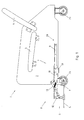
- a chair seating 1 is shown schematically in a vertical sectional view.
- the sectional plane corresponds to the center plane of the chair 1, which comprises two side parts 2, of which in the Fig. 1 as a result of the sectional view, only the rear side part 2 is shown in the viewing direction.
- the adjustable footrest 5 is shown in an extended position, in which a user who has taken a seat on the seating 1, comfortably his feet can set up on the footboard 5.
- the footboard 5 is formed in the illustrated seating 1 as a one-piece, rectangular plate-shaped component. However, the geometry of the footboard 5 is of minor importance with respect to the present invention.
- the footboard 5 is fixed on opposite sides, each with an adjusting mechanism 6 on one of the two side parts 2 of the chair 1.
- the adjusting mechanisms 6 of the chair 1 are in the Essentially identically formed, which is why the representation of both adjusting mechanisms 6 in the drawing is unnecessary.
- the adjustment mechanism 6 shown has, on the one hand, a displacement mechanism 7 in the form of a rail system and, on the other hand, a pivoting mechanism 8.
- the displacement mechanism 7 has a fixed rail 9 arranged on the side part 2 of the seat 1 and a rail 10 displaceably guided along the fixed rail 9 and carrying the pivoting mechanism 8.
- the adjusting mechanism 7 is shown separately in a perspective view.
- the adjusting mechanism 6 has a front and a rear support arm 11,12, which are both pivotally fixed to the sliding rail 10. At the lower end of the support arms 11,12 the footrest 5 is pivotally mounted.
- the two support arms 11,12 are interconnected via a control lever 13, wherein the control lever 13 is pivotally connected to each support arm 11,12.
- the control lever 13 is designed in two parts, wherein the two control members 14,15 of the control lever 13 are pivotally connected to each other.
- the rear arm 11 and the rear upper control member 14 of the control lever 13 are connected to a spring means 16 in the form of a spiral spring. The restoring force of the spring means 16 ensures that the pivoting mechanism 8 in the extended position of the footrest 5 in the in the Fig. 1 shown lower position remains.
- a lever member 17 is mounted, which has a relation to the seating 1 outwardly abkragenden connecting portion 18 and an adjoining, pointing upwards Operating section 19 includes.
- the operating section 19 is designed such that it can be accessed by the operator who has taken place on the seating 1, and operated as a hand lever.
- the lever member 17 can also be operated by a standing next to the seating 1 person with the foot as a pedal.
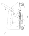
- the footboard 5 can be moved backwards, so that the footboard 5 comes into an area below the seat 3, as shown in the Fig. 3 is shown.
- the displaceably guided rail 10 of the adjusting mechanism 6 is pushed back along the rail 9 fixed to the side part 2.
- the position of the pivoting mechanism 8 remains unchanged and the footboard 5 in the lower position.
- control means 20 designed as a control pin are provided, which protrude into the further adjustment of the pivoting mechanisms 8. Due to this, the control lever 13 of the swing mechanism 8 comes into abutment with the control means 20 when the foot board 5 is shifted further backward.
- the control means 20 initially comes into abutment with a projecting portion of the control lever 13. The movement of the control lever 13 is thereby initially blocked by the control means 20. If the displaceably guided rail 10 is moved further from this position to the rear, this leads to a pivoting of the two with the toe board 5 connected support arms 11,12. In this case, the included between the rear arm 11 and the rear control member 14 of the control lever 13 angle increases, whereby the provided between the rear arm 11 and the rear control member 14 of the control lever 13 spring means 16 is pulled apart against its restoring force.
- the two control members 14,15 of the control lever 13 are pivoted to each other when adjusting from the extended position to the retracted position, starting from a stretched arrangement.
- the two support arms 11,12 are in the direction of displacement about their connection points 21,22 with the displaceably arranged rail 10, starting from a substantially vertical position in one Tilted position.
- This pivoting has a lifting of the footboard 5 in the upper position result.
- the pivoting mechanism 8 is held in the retracted position only by a blockage of the pivoting mechanism 8, resulting from the arrangement of acting in this function as a securing means against lowering of theticianbretts 5 control means 20 with respect to the pivoting mechanism 8, in particular the pivot lever 13 ,
- the adjusting mechanism 6' also has a displacement mechanism 7 and a pivot mechanism 8 'held displaceably on it.
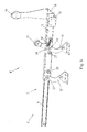
- the adjusting mechanism 6 ' is the sake of clarity separately in Fig. 6 shown, in the in the Fig. 5 position shown.
- the pivot mechanism 8 ' comprises two support arms 11', 12 'with which the footboard 5 is connected. Unlike in the Fig. 1 Seating furniture 1 shown, the two support arms 11 ', 12' in the chair 1 'not connected via a control lever. The rear support arm 11 ', however, is still spring-loaded such that the toe board 5 is held in the lower position or pivoted into the lower position, provided that this pivoting movement is not otherwise blocked.
- control means 20 ' is formed as a control block. This also protrudes into the displacement of the pivot mechanism 8 ', so that the pivot mechanism 8' comes in the process of the footboard 5 back under the seat 3 with the control means 20 'in abutment.
- the system on the control means 20 ' is about achieved a role 24, which is supported by the rear arm 11 '.
- the roller 24 engages under the control means 20 '.
- the control means 20 prevents a gift of the rear support arm 11', whereby the footboard 5 would be pivoted back into the lower position.
- the control means 20 'ultimately also assumes the function of Securing device which prevents unintentional lowering of the footboard.
- the rear support arm 11 ' also has a recess 26 which comes into abutment in the retracted position of the footboard 5 with a bolt 27.
- the front support arm 12 ' comes into contact with a further bolt 28. It is therefore occupied by the pivoting mechanism 8 'in the retracted position of the footboard 5 a defined position, this position is stabilized at the same time by contact with the bolt 27,28.
Landscapes
- Health & Medical Sciences (AREA)
- Dentistry (AREA)
- General Health & Medical Sciences (AREA)
- Special Chairs (AREA)
- Chairs For Special Purposes, Such As Reclining Chairs (AREA)
Applications Claiming Priority (1)
| Application Number | Priority Date | Filing Date | Title |
|---|---|---|---|
| DE102009020551A DE102009020551A1 (de) | 2009-05-08 | 2009-05-08 | Sitzmöbel mit einem ausziehbaren Fußbrett |
Publications (2)
| Publication Number | Publication Date |
|---|---|
| EP2255698A1 true EP2255698A1 (fr) | 2010-12-01 |
| EP2255698B1 EP2255698B1 (fr) | 2012-07-25 |
Family
ID=42799999
Family Applications (1)
| Application Number | Title | Priority Date | Filing Date |
|---|---|---|---|
| EP10159441A Not-in-force EP2255698B1 (fr) | 2009-05-08 | 2010-04-09 | Siège doté d'un repose-pied amovible |
Country Status (2)
| Country | Link |
|---|---|
| EP (1) | EP2255698B1 (fr) |
| DE (1) | DE102009020551A1 (fr) |
Citations (4)
| Publication number | Priority date | Publication date | Assignee | Title |
|---|---|---|---|---|
| DE3223597A1 (de) | 1982-06-24 | 1983-12-29 | Fritz 5461 Hausen Kerstholt | Schwenkbare und klappbare fussstuetze fuer sitz- und liegemoebel |
| US4765684A (en) | 1987-03-20 | 1988-08-23 | Kval Marketing Inc. | Multi-purpose chair with retractable knee rest |
| DE29700469U1 (de) * | 1997-01-13 | 1997-03-27 | Scheithauer, Hubert, 96279 Weidhausen | Ein- oder mehrsitziges Polstermöbelelement |
| DE20314508U1 (de) * | 2003-09-19 | 2003-12-11 | Bali Schaumstoff Gmbh | Verstellbares Sofa |
Family Cites Families (2)
| Publication number | Priority date | Publication date | Assignee | Title |
|---|---|---|---|---|
| US5277477A (en) * | 1991-07-08 | 1994-01-11 | Sharff Harold M | Transporter for the physically impaired |
| DE29908274U1 (de) * | 1999-05-08 | 1999-08-05 | Kohles, Harald, Dipl.-Ing. (FH), 96257 Redwitz | Sitzmöbel |
-
2009
- 2009-05-08 DE DE102009020551A patent/DE102009020551A1/de not_active Ceased
-
2010
- 2010-04-09 EP EP10159441A patent/EP2255698B1/fr not_active Not-in-force
Patent Citations (4)
| Publication number | Priority date | Publication date | Assignee | Title |
|---|---|---|---|---|
| DE3223597A1 (de) | 1982-06-24 | 1983-12-29 | Fritz 5461 Hausen Kerstholt | Schwenkbare und klappbare fussstuetze fuer sitz- und liegemoebel |
| US4765684A (en) | 1987-03-20 | 1988-08-23 | Kval Marketing Inc. | Multi-purpose chair with retractable knee rest |
| DE29700469U1 (de) * | 1997-01-13 | 1997-03-27 | Scheithauer, Hubert, 96279 Weidhausen | Ein- oder mehrsitziges Polstermöbelelement |
| DE20314508U1 (de) * | 2003-09-19 | 2003-12-11 | Bali Schaumstoff Gmbh | Verstellbares Sofa |
Also Published As
| Publication number | Publication date |
|---|---|
| EP2255698B1 (fr) | 2012-07-25 |
| DE102009020551A1 (de) | 2010-11-11 |
Similar Documents
| Publication | Publication Date | Title |
|---|---|---|
| EP3965617B1 (fr) | Siège comprenant une fonction wallaway à double moteur | |
| EP3167763A1 (fr) | Siège comprenant une partie têtière pivotante et séparée | |
| EP2609834B1 (fr) | Elément de siège et système d'armature associé | |
| DE2459908A1 (de) | Ausziehvorrichtung fuer eine fussstuetze bei einem lehnsessel | |
| EP2801293A1 (fr) | Elément de siège et sa garniture | |
| EP2777433A1 (fr) | Elément de siège et système d'armature associé | |
| EP2053941A1 (fr) | Chaise longue/fauteuil convertible | |
| DE102012006235B4 (de) | Schwenkbeschlag zum Verstellen eines Polstermöbels | |
| DE202020104509U1 (de) | Sitz- und Liegemöbel | |
| DE102011109668A1 (de) | Sitzmöbel mit verstellbarer Kopfstütze | |
| EP2255698B1 (fr) | Siège doté d'un repose-pied amovible | |
| DE102007044328A1 (de) | Möbel, insbesondere Sitzmöbel | |
| EP3146868B1 (fr) | Meuble multifonction | |
| EP2245964B1 (fr) | Siège doté d'une tringle de couplage reliant un dossier et un pied | |
| EP1754426B1 (fr) | Siège avec repose-jambes extractable | |
| DE10307738B4 (de) | Neigungsverstellvorrichtung für mindestens einen Teil einer Liege- oder Sitzfläche | |
| DE19635635C1 (de) | Sitzmöbel | |
| EP1118291A2 (fr) | Meuble pour s'asseoir | |
| DE20116145U1 (de) | Fußstütze für ein Sitz-/Liegemöbel | |
| EP1516564B1 (fr) | Meuble d'assise et/ou de couchage ajustable | |
| DE19520429B4 (de) | Verstellbares Sitz-/Liegemöbel | |
| DE1429367C (de) | Sitz oder Liegesessel | |
| EP4374741A1 (fr) | Meuble d'assise | |
| WO2026092849A1 (fr) | Meuble d'assise et/ou d'inclinaison doté d'une base réglable en pivotement | |
| DE1429367B2 (de) | Sitz- oder Liegesessel |
Legal Events
| Date | Code | Title | Description |
|---|---|---|---|
| PUAI | Public reference made under article 153(3) epc to a published international application that has entered the european phase |
Free format text: ORIGINAL CODE: 0009012 |
|
| AK | Designated contracting states |
Kind code of ref document: A1 Designated state(s): AT BE BG CH CY CZ DE DK EE ES FI FR GB GR HR HU IE IS IT LI LT LU LV MC MK MT NL NO PL PT RO SE SI SK SM TR |
|
| AX | Request for extension of the european patent |
Extension state: AL BA ME RS |
|
| 17P | Request for examination filed |
Effective date: 20110310 |
|
| 17Q | First examination report despatched |
Effective date: 20110404 |
|
| GRAJ | Information related to disapproval of communication of intention to grant by the applicant or resumption of examination proceedings by the epo deleted |
Free format text: ORIGINAL CODE: EPIDOSDIGR1 |
|
| GRAP | Despatch of communication of intention to grant a patent |
Free format text: ORIGINAL CODE: EPIDOSNIGR1 |
|
| RIN1 | Information on inventor provided before grant (corrected) |
Inventor name: DER ERFINDER HAT AUF SEINE NENNUNG VERZICHTET. |
|
| GRAS | Grant fee paid |
Free format text: ORIGINAL CODE: EPIDOSNIGR3 |
|
| GRAA | (expected) grant |
Free format text: ORIGINAL CODE: 0009210 |
|
| AK | Designated contracting states |
Kind code of ref document: B1 Designated state(s): AT BE BG CH CY CZ DE DK EE ES FI FR GB GR HR HU IE IS IT LI LT LU LV MC MK MT NL NO PL PT RO SE SI SK SM TR |
|
| REG | Reference to a national code |
Ref country code: GB Ref legal event code: FG4D Free format text: NOT ENGLISH |
|
| REG | Reference to a national code |
Ref country code: CH Ref legal event code: EP |
|
| REG | Reference to a national code |
Ref country code: AT Ref legal event code: REF Ref document number: 567367 Country of ref document: AT Kind code of ref document: T Effective date: 20120815 Ref country code: IE Ref legal event code: FG4D Free format text: LANGUAGE OF EP DOCUMENT: GERMAN |
|
| REG | Reference to a national code |
Ref country code: DE Ref legal event code: R096 Ref document number: 502010001057 Country of ref document: DE Effective date: 20120920 |
|
| REG | Reference to a national code |
Ref country code: NL Ref legal event code: VDEP Effective date: 20120725 |
|
| REG | Reference to a national code |
Ref country code: LT Ref legal event code: MG4D Effective date: 20120725 |
|
| PG25 | Lapsed in a contracting state [announced via postgrant information from national office to epo] |
Ref country code: CY Free format text: LAPSE BECAUSE OF FAILURE TO SUBMIT A TRANSLATION OF THE DESCRIPTION OR TO PAY THE FEE WITHIN THE PRESCRIBED TIME-LIMIT Effective date: 20120725 Ref country code: HR Free format text: LAPSE BECAUSE OF FAILURE TO SUBMIT A TRANSLATION OF THE DESCRIPTION OR TO PAY THE FEE WITHIN THE PRESCRIBED TIME-LIMIT Effective date: 20120725 Ref country code: FI Free format text: LAPSE BECAUSE OF FAILURE TO SUBMIT A TRANSLATION OF THE DESCRIPTION OR TO PAY THE FEE WITHIN THE PRESCRIBED TIME-LIMIT Effective date: 20120725 Ref country code: IS Free format text: LAPSE BECAUSE OF FAILURE TO SUBMIT A TRANSLATION OF THE DESCRIPTION OR TO PAY THE FEE WITHIN THE PRESCRIBED TIME-LIMIT Effective date: 20121125 Ref country code: LT Free format text: LAPSE BECAUSE OF FAILURE TO SUBMIT A TRANSLATION OF THE DESCRIPTION OR TO PAY THE FEE WITHIN THE PRESCRIBED TIME-LIMIT Effective date: 20120725 Ref country code: NO Free format text: LAPSE BECAUSE OF FAILURE TO SUBMIT A TRANSLATION OF THE DESCRIPTION OR TO PAY THE FEE WITHIN THE PRESCRIBED TIME-LIMIT Effective date: 20121025 |
|
| PG25 | Lapsed in a contracting state [announced via postgrant information from national office to epo] |
Ref country code: LV Free format text: LAPSE BECAUSE OF FAILURE TO SUBMIT A TRANSLATION OF THE DESCRIPTION OR TO PAY THE FEE WITHIN THE PRESCRIBED TIME-LIMIT Effective date: 20120725 Ref country code: SE Free format text: LAPSE BECAUSE OF FAILURE TO SUBMIT A TRANSLATION OF THE DESCRIPTION OR TO PAY THE FEE WITHIN THE PRESCRIBED TIME-LIMIT Effective date: 20120725 Ref country code: PL Free format text: LAPSE BECAUSE OF FAILURE TO SUBMIT A TRANSLATION OF THE DESCRIPTION OR TO PAY THE FEE WITHIN THE PRESCRIBED TIME-LIMIT Effective date: 20120725 Ref country code: SI Free format text: LAPSE BECAUSE OF FAILURE TO SUBMIT A TRANSLATION OF THE DESCRIPTION OR TO PAY THE FEE WITHIN THE PRESCRIBED TIME-LIMIT Effective date: 20120725 Ref country code: PT Free format text: LAPSE BECAUSE OF FAILURE TO SUBMIT A TRANSLATION OF THE DESCRIPTION OR TO PAY THE FEE WITHIN THE PRESCRIBED TIME-LIMIT Effective date: 20121126 |
|
| PG25 | Lapsed in a contracting state [announced via postgrant information from national office to epo] |
Ref country code: NL Free format text: LAPSE BECAUSE OF FAILURE TO SUBMIT A TRANSLATION OF THE DESCRIPTION OR TO PAY THE FEE WITHIN THE PRESCRIBED TIME-LIMIT Effective date: 20120725 |
|
| PG25 | Lapsed in a contracting state [announced via postgrant information from national office to epo] |
Ref country code: EE Free format text: LAPSE BECAUSE OF FAILURE TO SUBMIT A TRANSLATION OF THE DESCRIPTION OR TO PAY THE FEE WITHIN THE PRESCRIBED TIME-LIMIT Effective date: 20120725 Ref country code: DK Free format text: LAPSE BECAUSE OF FAILURE TO SUBMIT A TRANSLATION OF THE DESCRIPTION OR TO PAY THE FEE WITHIN THE PRESCRIBED TIME-LIMIT Effective date: 20120725 Ref country code: ES Free format text: LAPSE BECAUSE OF FAILURE TO SUBMIT A TRANSLATION OF THE DESCRIPTION OR TO PAY THE FEE WITHIN THE PRESCRIBED TIME-LIMIT Effective date: 20121105 Ref country code: CZ Free format text: LAPSE BECAUSE OF FAILURE TO SUBMIT A TRANSLATION OF THE DESCRIPTION OR TO PAY THE FEE WITHIN THE PRESCRIBED TIME-LIMIT Effective date: 20120725 Ref country code: RO Free format text: LAPSE BECAUSE OF FAILURE TO SUBMIT A TRANSLATION OF THE DESCRIPTION OR TO PAY THE FEE WITHIN THE PRESCRIBED TIME-LIMIT Effective date: 20120725 |
|
| PG25 | Lapsed in a contracting state [announced via postgrant information from national office to epo] |
Ref country code: IT Free format text: LAPSE BECAUSE OF FAILURE TO SUBMIT A TRANSLATION OF THE DESCRIPTION OR TO PAY THE FEE WITHIN THE PRESCRIBED TIME-LIMIT Effective date: 20120725 Ref country code: SK Free format text: LAPSE BECAUSE OF FAILURE TO SUBMIT A TRANSLATION OF THE DESCRIPTION OR TO PAY THE FEE WITHIN THE PRESCRIBED TIME-LIMIT Effective date: 20120725 |
|
| PLBE | No opposition filed within time limit |
Free format text: ORIGINAL CODE: 0009261 |
|
| STAA | Information on the status of an ep patent application or granted ep patent |
Free format text: STATUS: NO OPPOSITION FILED WITHIN TIME LIMIT |
|
| 26N | No opposition filed |
Effective date: 20130426 |
|
| PG25 | Lapsed in a contracting state [announced via postgrant information from national office to epo] |
Ref country code: BG Free format text: LAPSE BECAUSE OF FAILURE TO SUBMIT A TRANSLATION OF THE DESCRIPTION OR TO PAY THE FEE WITHIN THE PRESCRIBED TIME-LIMIT Effective date: 20121025 |
|
| REG | Reference to a national code |
Ref country code: DE Ref legal event code: R097 Ref document number: 502010001057 Country of ref document: DE Effective date: 20130426 |
|
| BERE | Be: lapsed |
Owner name: FERDINAND LUSCH G.M.B.H. & CO. KG Effective date: 20130430 |
|
| PG25 | Lapsed in a contracting state [announced via postgrant information from national office to epo] |
Ref country code: MC Free format text: LAPSE BECAUSE OF FAILURE TO SUBMIT A TRANSLATION OF THE DESCRIPTION OR TO PAY THE FEE WITHIN THE PRESCRIBED TIME-LIMIT Effective date: 20120725 |
|
| REG | Reference to a national code |
Ref country code: IE Ref legal event code: MM4A |
|
| PG25 | Lapsed in a contracting state [announced via postgrant information from national office to epo] |
Ref country code: BE Free format text: LAPSE BECAUSE OF NON-PAYMENT OF DUE FEES Effective date: 20130430 |
|
| REG | Reference to a national code |
Ref country code: FR Ref legal event code: ST Effective date: 20131231 |
|
| PG25 | Lapsed in a contracting state [announced via postgrant information from national office to epo] |
Ref country code: FR Free format text: LAPSE BECAUSE OF NON-PAYMENT OF DUE FEES Effective date: 20130430 |
|
| PG25 | Lapsed in a contracting state [announced via postgrant information from national office to epo] |
Ref country code: IE Free format text: LAPSE BECAUSE OF NON-PAYMENT OF DUE FEES Effective date: 20130409 |
|
| REG | Reference to a national code |
Ref country code: CH Ref legal event code: PL |
|
| GBPC | Gb: european patent ceased through non-payment of renewal fee |
Effective date: 20140409 |
|
| PG25 | Lapsed in a contracting state [announced via postgrant information from national office to epo] |
Ref country code: GB Free format text: LAPSE BECAUSE OF NON-PAYMENT OF DUE FEES Effective date: 20140409 Ref country code: CH Free format text: LAPSE BECAUSE OF NON-PAYMENT OF DUE FEES Effective date: 20140430 Ref country code: LI Free format text: LAPSE BECAUSE OF NON-PAYMENT OF DUE FEES Effective date: 20140430 |
|
| PG25 | Lapsed in a contracting state [announced via postgrant information from national office to epo] |
Ref country code: MT Free format text: LAPSE BECAUSE OF FAILURE TO SUBMIT A TRANSLATION OF THE DESCRIPTION OR TO PAY THE FEE WITHIN THE PRESCRIBED TIME-LIMIT Effective date: 20120725 |
|
| PG25 | Lapsed in a contracting state [announced via postgrant information from national office to epo] |
Ref country code: SM Free format text: LAPSE BECAUSE OF FAILURE TO SUBMIT A TRANSLATION OF THE DESCRIPTION OR TO PAY THE FEE WITHIN THE PRESCRIBED TIME-LIMIT Effective date: 20120725 |
|
| PG25 | Lapsed in a contracting state [announced via postgrant information from national office to epo] |
Ref country code: TR Free format text: LAPSE BECAUSE OF FAILURE TO SUBMIT A TRANSLATION OF THE DESCRIPTION OR TO PAY THE FEE WITHIN THE PRESCRIBED TIME-LIMIT Effective date: 20120725 |
|
| PG25 | Lapsed in a contracting state [announced via postgrant information from national office to epo] |
Ref country code: LU Free format text: LAPSE BECAUSE OF NON-PAYMENT OF DUE FEES Effective date: 20130409 Ref country code: MK Free format text: LAPSE BECAUSE OF FAILURE TO SUBMIT A TRANSLATION OF THE DESCRIPTION OR TO PAY THE FEE WITHIN THE PRESCRIBED TIME-LIMIT Effective date: 20120725 Ref country code: HU Free format text: LAPSE BECAUSE OF FAILURE TO SUBMIT A TRANSLATION OF THE DESCRIPTION OR TO PAY THE FEE WITHIN THE PRESCRIBED TIME-LIMIT; INVALID AB INITIO Effective date: 20100409 |
|
| PGFP | Annual fee paid to national office [announced via postgrant information from national office to epo] |
Ref country code: DE Payment date: 20150424 Year of fee payment: 6 |
|
| PG25 | Lapsed in a contracting state [announced via postgrant information from national office to epo] |
Ref country code: GR Free format text: LAPSE BECAUSE OF NON-PAYMENT OF DUE FEES Effective date: 20120725 |
|
| REG | Reference to a national code |
Ref country code: AT Ref legal event code: MM01 Ref document number: 567367 Country of ref document: AT Kind code of ref document: T Effective date: 20150409 |
|
| PG25 | Lapsed in a contracting state [announced via postgrant information from national office to epo] |
Ref country code: AT Free format text: LAPSE BECAUSE OF NON-PAYMENT OF DUE FEES Effective date: 20150409 |
|
| REG | Reference to a national code |
Ref country code: DE Ref legal event code: R119 Ref document number: 502010001057 Country of ref document: DE |
|
| PG25 | Lapsed in a contracting state [announced via postgrant information from national office to epo] |
Ref country code: DE Free format text: LAPSE BECAUSE OF NON-PAYMENT OF DUE FEES Effective date: 20161101 |