EP2256277B1 - Integrierte Vorrichtung zur Hindernisdetektion und Fahrtanzeige für ein motorisiertes Tor oder dergleichen - Google Patents
Integrierte Vorrichtung zur Hindernisdetektion und Fahrtanzeige für ein motorisiertes Tor oder dergleichen Download PDFInfo
- Publication number
- EP2256277B1 EP2256277B1 EP10161955A EP10161955A EP2256277B1 EP 2256277 B1 EP2256277 B1 EP 2256277B1 EP 10161955 A EP10161955 A EP 10161955A EP 10161955 A EP10161955 A EP 10161955A EP 2256277 B1 EP2256277 B1 EP 2256277B1
- Authority
- EP
- European Patent Office
- Prior art keywords
- receiver
- transmitter
- gate
- indicator light
- flashing
- Prior art date
- Legal status (The legal status is an assumption and is not a legal conclusion. Google has not performed a legal analysis and makes no representation as to the accuracy of the status listed.)
- Active
Links
Images

Classifications
-
- E—FIXED CONSTRUCTIONS
- E05—LOCKS; KEYS; WINDOW OR DOOR FITTINGS; SAFES
- E05F—DEVICES FOR MOVING WINGS INTO OPEN OR CLOSED POSITION; CHECKS FOR WINGS; WING FITTINGS NOT OTHERWISE PROVIDED FOR, CONCERNED WITH THE FUNCTIONING OF THE WING
- E05F15/00—Power-operated mechanisms for wings
- E05F15/40—Safety devices, e.g. detection of obstructions or end positions
- E05F15/42—Detection using safety edges
- E05F15/43—Detection using safety edges responsive to disruption of energy beams, e.g. light or sound
-
- E—FIXED CONSTRUCTIONS
- E05—LOCKS; KEYS; WINDOW OR DOOR FITTINGS; SAFES
- E05F—DEVICES FOR MOVING WINGS INTO OPEN OR CLOSED POSITION; CHECKS FOR WINGS; WING FITTINGS NOT OTHERWISE PROVIDED FOR, CONCERNED WITH THE FUNCTIONING OF THE WING
- E05F15/00—Power-operated mechanisms for wings
- E05F15/40—Safety devices, e.g. detection of obstructions or end positions
-
- E—FIXED CONSTRUCTIONS
- E05—LOCKS; KEYS; WINDOW OR DOOR FITTINGS; SAFES
- E05F—DEVICES FOR MOVING WINGS INTO OPEN OR CLOSED POSITION; CHECKS FOR WINGS; WING FITTINGS NOT OTHERWISE PROVIDED FOR, CONCERNED WITH THE FUNCTIONING OF THE WING
- E05F15/00—Power-operated mechanisms for wings
-
- E—FIXED CONSTRUCTIONS
- E05—LOCKS; KEYS; WINDOW OR DOOR FITTINGS; SAFES
- E05F—DEVICES FOR MOVING WINGS INTO OPEN OR CLOSED POSITION; CHECKS FOR WINGS; WING FITTINGS NOT OTHERWISE PROVIDED FOR, CONCERNED WITH THE FUNCTIONING OF THE WING
- E05F15/00—Power-operated mechanisms for wings
- E05F15/40—Safety devices, e.g. detection of obstructions or end positions
- E05F15/42—Detection using safety edges
- E05F15/43—Detection using safety edges responsive to disruption of energy beams, e.g. light or sound
- E05F2015/434—Detection using safety edges responsive to disruption of energy beams, e.g. light or sound with cameras or optical sensors
- E05F2015/435—Detection using safety edges responsive to disruption of energy beams, e.g. light or sound with cameras or optical sensors by interruption of the beam
- E05F2015/437—Detection using safety edges responsive to disruption of energy beams, e.g. light or sound with cameras or optical sensors by interruption of the beam the beam being perpendicular to the wing edge
-
- E—FIXED CONSTRUCTIONS
- E05—LOCKS; KEYS; WINDOW OR DOOR FITTINGS; SAFES
- E05F—DEVICES FOR MOVING WINGS INTO OPEN OR CLOSED POSITION; CHECKS FOR WINGS; WING FITTINGS NOT OTHERWISE PROVIDED FOR, CONCERNED WITH THE FUNCTIONING OF THE WING
- E05F15/00—Power-operated mechanisms for wings
- E05F15/40—Safety devices, e.g. detection of obstructions or end positions
- E05F15/42—Detection using safety edges
- E05F2015/487—Fault detection of safety edges
-
- E—FIXED CONSTRUCTIONS
- E05—LOCKS; KEYS; WINDOW OR DOOR FITTINGS; SAFES
- E05Y—INDEXING SCHEME ASSOCIATED WITH SUBCLASSES E05D AND E05F, RELATING TO CONSTRUCTION ELEMENTS, ELECTRIC CONTROL, POWER SUPPLY, POWER SIGNAL OR TRANSMISSION, USER INTERFACES, MOUNTING OR COUPLING, DETAILS, ACCESSORIES, AUXILIARY OPERATIONS NOT OTHERWISE PROVIDED FOR, APPLICATION THEREOF
- E05Y2400/00—Electronic control; Electrical power; Power supply; Power or signal transmission; User interfaces
- E05Y2400/10—Electronic control
- E05Y2400/45—Control modes
- E05Y2400/452—Control modes for saving energy, e.g. sleep or wake-up
-
- E—FIXED CONSTRUCTIONS
- E05—LOCKS; KEYS; WINDOW OR DOOR FITTINGS; SAFES
- E05Y—INDEXING SCHEME ASSOCIATED WITH SUBCLASSES E05D AND E05F, RELATING TO CONSTRUCTION ELEMENTS, ELECTRIC CONTROL, POWER SUPPLY, POWER SIGNAL OR TRANSMISSION, USER INTERFACES, MOUNTING OR COUPLING, DETAILS, ACCESSORIES, AUXILIARY OPERATIONS NOT OTHERWISE PROVIDED FOR, APPLICATION THEREOF
- E05Y2400/00—Electronic control; Electrical power; Power supply; Power or signal transmission; User interfaces
- E05Y2400/61—Power supply
-
- E—FIXED CONSTRUCTIONS
- E05—LOCKS; KEYS; WINDOW OR DOOR FITTINGS; SAFES
- E05Y—INDEXING SCHEME ASSOCIATED WITH SUBCLASSES E05D AND E05F, RELATING TO CONSTRUCTION ELEMENTS, ELECTRIC CONTROL, POWER SUPPLY, POWER SIGNAL OR TRANSMISSION, USER INTERFACES, MOUNTING OR COUPLING, DETAILS, ACCESSORIES, AUXILIARY OPERATIONS NOT OTHERWISE PROVIDED FOR, APPLICATION THEREOF
- E05Y2400/00—Electronic control; Electrical power; Power supply; Power or signal transmission; User interfaces
- E05Y2400/80—User interfaces
- E05Y2400/81—Feedback to user, e.g. tactile
- E05Y2400/818—Visual
- E05Y2400/822—Light emitters, e.g. light emitting diodes [LED]
-
- E—FIXED CONSTRUCTIONS
- E05—LOCKS; KEYS; WINDOW OR DOOR FITTINGS; SAFES
- E05Y—INDEXING SCHEME ASSOCIATED WITH SUBCLASSES E05D AND E05F, RELATING TO CONSTRUCTION ELEMENTS, ELECTRIC CONTROL, POWER SUPPLY, POWER SIGNAL OR TRANSMISSION, USER INTERFACES, MOUNTING OR COUPLING, DETAILS, ACCESSORIES, AUXILIARY OPERATIONS NOT OTHERWISE PROVIDED FOR, APPLICATION THEREOF
- E05Y2400/00—Electronic control; Electrical power; Power supply; Power or signal transmission; User interfaces
- E05Y2400/80—User interfaces
- E05Y2400/81—Feedback to user, e.g. tactile
- E05Y2400/83—Travel information display
-
- E—FIXED CONSTRUCTIONS
- E05—LOCKS; KEYS; WINDOW OR DOOR FITTINGS; SAFES
- E05Y—INDEXING SCHEME ASSOCIATED WITH SUBCLASSES E05D AND E05F, RELATING TO CONSTRUCTION ELEMENTS, ELECTRIC CONTROL, POWER SUPPLY, POWER SIGNAL OR TRANSMISSION, USER INTERFACES, MOUNTING OR COUPLING, DETAILS, ACCESSORIES, AUXILIARY OPERATIONS NOT OTHERWISE PROVIDED FOR, APPLICATION THEREOF
- E05Y2600/00—Mounting or coupling arrangements for elements provided for in this subclass
- E05Y2600/40—Mounting location; Visibility of the elements
- E05Y2600/45—Mounting location; Visibility of the elements in or on the fixed frame
-
- E—FIXED CONSTRUCTIONS
- E05—LOCKS; KEYS; WINDOW OR DOOR FITTINGS; SAFES
- E05Y—INDEXING SCHEME ASSOCIATED WITH SUBCLASSES E05D AND E05F, RELATING TO CONSTRUCTION ELEMENTS, ELECTRIC CONTROL, POWER SUPPLY, POWER SIGNAL OR TRANSMISSION, USER INTERFACES, MOUNTING OR COUPLING, DETAILS, ACCESSORIES, AUXILIARY OPERATIONS NOT OTHERWISE PROVIDED FOR, APPLICATION THEREOF
- E05Y2800/00—Details, accessories and auxiliary operations not otherwise provided for
- E05Y2800/20—Combinations of elements
- E05Y2800/21—Combinations of elements of identical elements, e.g. of identical compression springs
-
- E—FIXED CONSTRUCTIONS
- E05—LOCKS; KEYS; WINDOW OR DOOR FITTINGS; SAFES
- E05Y—INDEXING SCHEME ASSOCIATED WITH SUBCLASSES E05D AND E05F, RELATING TO CONSTRUCTION ELEMENTS, ELECTRIC CONTROL, POWER SUPPLY, POWER SIGNAL OR TRANSMISSION, USER INTERFACES, MOUNTING OR COUPLING, DETAILS, ACCESSORIES, AUXILIARY OPERATIONS NOT OTHERWISE PROVIDED FOR, APPLICATION THEREOF
- E05Y2800/00—Details, accessories and auxiliary operations not otherwise provided for
- E05Y2800/26—Form or shape
- E05Y2800/29—Form or shape forming a unitary piece with another element
-
- E—FIXED CONSTRUCTIONS
- E05—LOCKS; KEYS; WINDOW OR DOOR FITTINGS; SAFES
- E05Y—INDEXING SCHEME ASSOCIATED WITH SUBCLASSES E05D AND E05F, RELATING TO CONSTRUCTION ELEMENTS, ELECTRIC CONTROL, POWER SUPPLY, POWER SIGNAL OR TRANSMISSION, USER INTERFACES, MOUNTING OR COUPLING, DETAILS, ACCESSORIES, AUXILIARY OPERATIONS NOT OTHERWISE PROVIDED FOR, APPLICATION THEREOF
- E05Y2900/00—Application of doors, windows, wings or fittings thereof
- E05Y2900/40—Application of doors, windows, wings or fittings thereof for gates
Definitions
- the present finding concerns an integrated device for obstacle detection and travel indication for a motorised gate or the like, with particular reference to sliding and swinging gates, barriers, automatic doors and the like.
- the same standard forces at least one optical device for detecting obstacles to be installed, in many installation conditions.
- the detection of obstacles is carried out by applying an electromagnetic beam in the infrared field, between a transmitting unit and a receiving unit, arranged at opposite sides of the opening, the access of which, is controlled by a barrier or by a gate.
- the receiver When the infrared beam intercepts an object, the receiver sends a signal to the control unit, which is translated into a command to stop or reverse the motion of the motorisation unit.
- many pairs of photocells are applied installed in various positions on the pillars of the access opening of the gate or door, on their inner or outer side and at variable heights according to the use of the gate.
- indicator light devices which, synchronised with the movement of the door, warn the user that the opening or closing has begun, with the purpose of visually warning whoever is in the movement area of the gate.
- indicator light devices consist of yellow-orange semi transparent dome lamps, illuminated with synchronised flashing lights, with variable frequency, in general of the order of one flash per second.
- the light source consists of a common incandescent bulb or in some cases of LED lights, with a supply and control unit for synchronising the flashing, connected to the control station of the gear motor.
- the purpose of the present finding is combining the obstacle detection function with the indicator function, such that the indicator function is also used for diagnosing the anomalous operation of the detecting device.
- the light beam of which is suitably concentrated and directed by an optical deflector towards the area adjacent to the manoeuvring area of the gate.
- One or more LED lights are used also with a function of diagnosing the anomalous operation of the detecting device, consisting of one or more pairs of infrared photocells.
- the LEDs of the transmitter could be switched on, whereas the LEDs of the receiver could be switched off, this condition being sufficient to identify the condition of the interruption of the light beam by an obstacle.
- the LED indicators In a system with many pairs of photocells, applied to the same access opening, it is possible to identify, through the LED indicators, which pair is engaged by an obstacle, or which pair of photocells has an anomalous or faulty operation condition. For example, if there are disturbances with the signal or if there is a misalignment between the transmitter and the receiver, when the gate receives the manoeuvre command, there is no actuation.
- the asymmetric operation of the LEDs between the receiver and the transmitter which is essential for this invention, allows the installer and the user to immediately identify which pair of photocells is misaligned, or engaged. In a completely analogous manner, it is also possible to ensure diagnosing operations for a possible fault of the photocell.
- the indicator LEDs for example, by varying the indication frequency, can help the installer carry out the correct centring of the pair of photocells during the first installation.
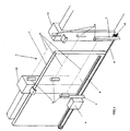
- the access opening 1 is closed by a mobile barrier (or gate 2) actuated by the motor 6, through the rack 8, along the tracks 9 between the mechanical end stops 10.
- the transmitter 3 and receiver 4 elements of the pairs of photocells which, through the infrared signal 5, intercept possible obstacles during the actuation, sending a suitable signal to the control unit of the motor 6, being also supplied by it, are fixed to the side pillars 11 of the access opening and to the columns 7.
- indicator lights are not represented, since they are integrated in the transmitter and receiver elements 3 or 4 of the photocells, the detail of which is illustrated in fig.2.
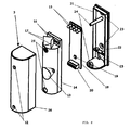
- Fig.2 represents a three dimensional exploded view of one of the elements 3 or 4.
- the base 21 is fixed to a pillar 11 or to the column 7 with some screws passing through the holes 23 and acts as a support for the printed circuit 18, which rests on the support element 22 and is connected to the control unit of the motor 6 through a cable passing through the hole 23.
- the printed circuit 18, represented in a simplified manner, has a photodiode 19 for the detection function, a terminal box 20 for the connection and a group 15 comprising at least one power LED for the flashing indication function.
- the printed circuit 18 is closed by a lid 14, which has the function of directing the indicator light beam of the LEDs 15 passing in the holes 16 through the deflector 17 and of protecting the photodiode 19 from interferences through the cone 13.
- the device is also closed by an outer lid 3 fixed by screws passing through the holes 12 and 25 on the tabs 24 of the base 21. All of this is closed in a semi-transparent outer half-shell 26, which allows the infrared beam to pass towards the deviator cone and simultaneously makes the indicator LEDs visible.
- the integration of the indicator system with the device for detecting obstacles provides the user and the installer with the possibility of highlighting possible anomalies and faults of the device through the indicator device.
- the activation of the flashing indicator device in the receiver 4 is enabled only if it is during the reception of an infrared signal 5. Therefore, if for some reason the activation of the door were to be carried out with the device for detecting obstacles not active, it would be highlighted to the user by the absence of flashing of the receiver, with however the flashing of the transmitter.
- This logic is particularly useful in the case in which it is wished to connect many pairs of photocells in series, with the purpose of completely checking the manoeuvre area of the door, at different heights so that, in some cases these pairs of detection devices are also applied.
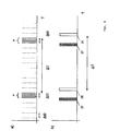
- the graph a) represents the signal 5, obtained by the emission of infrared pulses of the transmitter 3, whereas the graph b) represents the emission of light pulses of the indicator light 15 of the transmitter 3 and of the receiver 4 (indicated respectively with reference numerals 27 and 28).
- the transmitter 3, at the flashing of its indicator light 15, emits a packet of pulses P with a higher frequency (for example five pulse in Is, with a period ⁇ t1 20 ⁇ s), the receiver 4 once identified the packet of pulses, commands the flashing of its indicator light.
- the flashing of the transmitter 3 and of the receiver 4 are synchronised with a frequency of 1/ ⁇ t, the delay between the first and the second flash being practically negligible.
- the sending of the packet P occurs with a periodicity indicated in the figure as ⁇ T (generally of the order of 1 s).
- Each pair of photocells can be associated with a characteristic transmission frequency of the infrared signal, set during installation, by associating, for example, each pair of transmitters 3 and receivers 4 with an address and allowing the receiver 4 to recognise the signal of the transmitter 3 associated with it. In this way, overlapping between the signal of different pairs of photocells, in the case in which installations are carried out on the same detection plane, is avoided.
Landscapes
- Geophysics And Detection Of Objects (AREA)
- Power-Operated Mechanisms For Wings (AREA)
- Radar Systems Or Details Thereof (AREA)
- Train Traffic Observation, Control, And Security (AREA)
- Control Of Motors That Do Not Use Commutators (AREA)
- Radio Relay Systems (AREA)
Claims (5)
- Integrierte Vorrichtung zur Hinderniserkennung und Verfahranzeige für ein motorisiertes Tor oder dergleichen, die mindestens einen Sender (3) und einen Empfänger (4) für ein Infrarotsignal (5) umfasst, die auf den Außenseiten der von dem Tor (2) oder dergleichen kontrollierten Zugangsöffnung (1) angeordnet sind und der Steuereinheit des Aktuators (6) des Tors melden, wenn dieses Signal durch ein Hindernis gesperrt wird, wobei sowohl der Sender (3) als auch der Empfänger (4) einen Blinkleuchtmelder (15) umfassen, der während des Öffnens und Schließens des Tors aktiviert wird, um auf das Verfahren des Tors hinzuweisen, wobei die Aktivierung des Leuchtmelders (15) des Empfängers (4) durch den Empfang des Infrarotsignals (5) von dem mit diesem Empfänger (4) gekoppelten Sender (3) gesteuert wird, so dass im Falle des Verfahrens des Tors mit versagender Hinderniserkennung der Leuchtmelder (15) des Senders (3) aktiviert wird, während der Leuchtmelder (15) des Empfängers (4) nicht aktiviert wird, wodurch das Versagen der Hinderniserkennung angezeigt wird.
- Vorrichtung nach Anspruch 1, dadurch gekennzeichnet, dass der vom Blinkleuchtmelder (15) emittierte Lichtstrahl (5) von einem symmetrischen optischen Deflektor (17) in eine Richtung nach außerhalb der Zugangsöffnung abgelenkt wird.
- Vorrichtung nach Anspruch 1 oder 2, dadurch gekennzeichnet, dass der Betrieb des Blinkleuchtmelders (15) mit vielerlei Modi werden kann, von denen mindestens einer zur Anzeige des Öffnungs - und Schließvorgangs des Aktuators (6) mit einer festen Blinkfrequenz und einer variablen Frequenz entsprechend der Fluchtung des Paares aus Sender (3) und Empfänger (4) für das Infrarotsignal (5) dient.
- Vorrichtung nach einem oder mehreren der vorhergehenden Ansprüche, dadurch gekennzeichnet, dass das Blinken des Leuchtmelders des Empfängers (4) mit dem des Senders (3) synchronisiert wird, indem eine Folge von Infrarotimpulsen mit mindestens zwei Übertragungsfrequenzen gesendet wird.
- Vorrichtung nach Anspruch 4, dadurch gekennzeichnet, dass die Synchronisation durch Übertragen einer Impulsfolge mit mindestens zwei verschiedenen Signaldauern erfolgt.
Applications Claiming Priority (1)
| Application Number | Priority Date | Filing Date | Title |
|---|---|---|---|
| ITVI2009A000123A IT1397307B1 (it) | 2009-05-28 | 2009-05-28 | Dispositivo integrato di segnalazione e di rilevamento della presenza di ostacoli per un sistema di motorizzazione di cancelli e simili |
Publications (3)
| Publication Number | Publication Date |
|---|---|
| EP2256277A1 EP2256277A1 (de) | 2010-12-01 |
| EP2256277B1 true EP2256277B1 (de) | 2012-12-05 |
| EP2256277B9 EP2256277B9 (de) | 2013-03-27 |
Family
ID=41450012
Family Applications (1)
| Application Number | Title | Priority Date | Filing Date |
|---|---|---|---|
| EP10161955A Active EP2256277B9 (de) | 2009-05-28 | 2010-05-05 | Integrierte Vorrichtung zur Hindernisdetektion und Fahrtanzeige für ein motorisiertes Tor oder dergleichen |
Country Status (3)
| Country | Link |
|---|---|
| EP (1) | EP2256277B9 (de) |
| HR (1) | HRP20130179T1 (de) |
| IT (1) | IT1397307B1 (de) |
Families Citing this family (4)
| Publication number | Priority date | Publication date | Assignee | Title |
|---|---|---|---|---|
| ITVI20130065A1 (it) * | 2013-03-12 | 2014-09-13 | Bft S P A | Dispositivo di rilevamento di ostacoli per un cancello motorizzato o simili |
| US10619397B2 (en) | 2015-09-14 | 2020-04-14 | Rytec Corporation | System and method for safety management in roll-up doors |
| US12404714B2 (en) | 2015-09-14 | 2025-09-02 | Rytec Corporation | System and method for safety management in roll-up doors |
| EP3899186A4 (de) | 2018-12-21 | 2022-10-05 | Rytec Corporation | Sicherheitssystem und -verfahren für rolltore |
Family Cites Families (2)
| Publication number | Priority date | Publication date | Assignee | Title |
|---|---|---|---|---|
| ITTV20050055A1 (it) * | 2005-04-22 | 2006-10-23 | Nice Spa | Dispositivo luminoso. |
| US20080186168A1 (en) * | 2007-02-05 | 2008-08-07 | Findisa S.R.L. | Electronic system for controlling gate or door opening |
-
2009
- 2009-05-28 IT ITVI2009A000123A patent/IT1397307B1/it active
-
2010
- 2010-05-05 EP EP10161955A patent/EP2256277B9/de active Active
-
2013
- 2013-03-01 HR HRP20130179AT patent/HRP20130179T1/hr unknown
Also Published As
| Publication number | Publication date |
|---|---|
| HRP20130179T1 (hr) | 2013-03-31 |
| EP2256277A1 (de) | 2010-12-01 |
| IT1397307B1 (it) | 2013-01-04 |
| ITVI20090123A1 (it) | 2010-11-29 |
| EP2256277B9 (de) | 2013-03-27 |
Similar Documents
| Publication | Publication Date | Title |
|---|---|---|
| EP2256277B9 (de) | Integrierte Vorrichtung zur Hindernisdetektion und Fahrtanzeige für ein motorisiertes Tor oder dergleichen | |
| US8575538B2 (en) | Safety system for safeguarding a moving, guided motion element that blocks the movement of the guided motion element from triggering the saftey mode | |
| US9421902B2 (en) | Motor vehicle comprising a plurality of lights to illuminate the area surrounding the vehicle to the side or rear | |
| US6597291B2 (en) | Garage door monitoring system | |
| US9830825B2 (en) | Warning and guidance system to assist the parking of a vehicle | |
| US4794248A (en) | Detection device having energy transmitters located at vertically spaced apart points along movable doors | |
| CN201240379Y (zh) | 应用于城市轨道交通站台的激光探测装置 | |
| JP3129439B2 (ja) | 検出システム | |
| EP2843173A1 (de) | Automatische Türsensorvorrichtung | |
| HRP20140087T1 (hr) | Konstrukcija sa svjetlom upozorenja na prepreku i postupak za upravljanje svjetlom upozorenja na prepreku | |
| EP3351500A1 (de) | Multifunktionaler aufzugslichtvorhang | |
| JPH11354831A (ja) | 狭い角度特性の光軸付きエリアセンサ | |
| US8878687B2 (en) | Automatic door sensor and functionality expansion module for use in the same | |
| JP4934227B1 (ja) | プラットホームドア装置の制御システム | |
| TWI760253B (zh) | 可調變光場範圍和具備高效能發射的通行感測器 | |
| JPH1067481A (ja) | エレベータのドアを再開放するための光バリア | |
| WO2007135371A1 (en) | Obstacle-detecting apparatus for a powered door system | |
| JP2014108833A (ja) | 乗客コンベヤ | |
| US6704471B1 (en) | System and method for detecting an obstruction in a power window | |
| US20080186168A1 (en) | Electronic system for controlling gate or door opening | |
| KR20090009363U (ko) | 자동문 안전센서 장치 | |
| US20110172827A1 (en) | Control system for a door wing | |
| EP2778333B1 (de) | Vorrichtung zur Hindernisdetektion für ein motorisiertes Tor oder dergleichen | |
| KR20130136132A (ko) | 공장 도어 어셈블리 | |
| CN102146759A (zh) | 一种用于沿门框运行的车库门的检测障碍物的安全系统 |
Legal Events
| Date | Code | Title | Description |
|---|---|---|---|
| PUAI | Public reference made under article 153(3) epc to a published international application that has entered the european phase |
Free format text: ORIGINAL CODE: 0009012 |
|
| AK | Designated contracting states |
Kind code of ref document: A1 Designated state(s): AL AT BE BG CH CY CZ DE DK EE ES FI FR GB GR HR HU IE IS IT LI LT LU LV MC MK MT NL NO PL PT RO SE SI SK SM TR |
|
| AX | Request for extension of the european patent |
Extension state: BA ME RS |
|
| 17P | Request for examination filed |
Effective date: 20110224 |
|
| RIN1 | Information on inventor provided before grant (corrected) |
Inventor name: SPREA, RENATO |
|
| RIN1 | Information on inventor provided before grant (corrected) |
Inventor name: SPREA, RENATO |
|
| RIN1 | Information on inventor provided before grant (corrected) |
Inventor name: SPREA, RENATO |
|
| 17Q | First examination report despatched |
Effective date: 20120125 |
|
| GRAP | Despatch of communication of intention to grant a patent |
Free format text: ORIGINAL CODE: EPIDOSNIGR1 |
|
| GRAS | Grant fee paid |
Free format text: ORIGINAL CODE: EPIDOSNIGR3 |
|
| GRAA | (expected) grant |
Free format text: ORIGINAL CODE: 0009210 |
|
| AK | Designated contracting states |
Kind code of ref document: B1 Designated state(s): AL AT BE BG CH CY CZ DE DK EE ES FI FR GB GR HR HU IE IS IT LI LT LU LV MC MK MT NL NO PL PT RO SE SI SK SM TR |
|
| REG | Reference to a national code |
Ref country code: GB Ref legal event code: FG4D |
|
| REG | Reference to a national code |
Ref country code: CH Ref legal event code: EP |
|
| REG | Reference to a national code |
Ref country code: AT Ref legal event code: REF Ref document number: 587397 Country of ref document: AT Kind code of ref document: T Effective date: 20121215 |
|
| REG | Reference to a national code |
Ref country code: IE Ref legal event code: FG4D |
|
| REG | Reference to a national code |
Ref country code: DE Ref legal event code: R096 Ref document number: 602010003918 Country of ref document: DE Effective date: 20130131 |
|
| REG | Reference to a national code |
Ref country code: HR Ref legal event code: TUEP Ref document number: P20130179 Country of ref document: HR |
|
| REG | Reference to a national code |
Ref country code: HR Ref legal event code: T1PR Ref document number: P20130179 Country of ref document: HR |
|
| REG | Reference to a national code |
Ref country code: AT Ref legal event code: MK05 Ref document number: 587397 Country of ref document: AT Kind code of ref document: T Effective date: 20121205 |
|
| PG25 | Lapsed in a contracting state [announced via postgrant information from national office to epo] |
Ref country code: ES Free format text: LAPSE BECAUSE OF FAILURE TO SUBMIT A TRANSLATION OF THE DESCRIPTION OR TO PAY THE FEE WITHIN THE PRESCRIBED TIME-LIMIT Effective date: 20130316 Ref country code: SE Free format text: LAPSE BECAUSE OF FAILURE TO SUBMIT A TRANSLATION OF THE DESCRIPTION OR TO PAY THE FEE WITHIN THE PRESCRIBED TIME-LIMIT Effective date: 20121205 Ref country code: NO Free format text: LAPSE BECAUSE OF FAILURE TO SUBMIT A TRANSLATION OF THE DESCRIPTION OR TO PAY THE FEE WITHIN THE PRESCRIBED TIME-LIMIT Effective date: 20130305 Ref country code: FI Free format text: LAPSE BECAUSE OF FAILURE TO SUBMIT A TRANSLATION OF THE DESCRIPTION OR TO PAY THE FEE WITHIN THE PRESCRIBED TIME-LIMIT Effective date: 20121205 Ref country code: LT Free format text: LAPSE BECAUSE OF FAILURE TO SUBMIT A TRANSLATION OF THE DESCRIPTION OR TO PAY THE FEE WITHIN THE PRESCRIBED TIME-LIMIT Effective date: 20121205 |
|
| REG | Reference to a national code |
Ref country code: NL Ref legal event code: VDEP Effective date: 20121205 |
|
| REG | Reference to a national code |
Ref country code: LT Ref legal event code: MG4D |
|
| PG25 | Lapsed in a contracting state [announced via postgrant information from national office to epo] |
Ref country code: LV Free format text: LAPSE BECAUSE OF FAILURE TO SUBMIT A TRANSLATION OF THE DESCRIPTION OR TO PAY THE FEE WITHIN THE PRESCRIBED TIME-LIMIT Effective date: 20121205 Ref country code: SI Free format text: LAPSE BECAUSE OF FAILURE TO SUBMIT A TRANSLATION OF THE DESCRIPTION OR TO PAY THE FEE WITHIN THE PRESCRIBED TIME-LIMIT Effective date: 20121205 Ref country code: GR Free format text: LAPSE BECAUSE OF FAILURE TO SUBMIT A TRANSLATION OF THE DESCRIPTION OR TO PAY THE FEE WITHIN THE PRESCRIBED TIME-LIMIT Effective date: 20130306 Ref country code: PL Free format text: LAPSE BECAUSE OF FAILURE TO SUBMIT A TRANSLATION OF THE DESCRIPTION OR TO PAY THE FEE WITHIN THE PRESCRIBED TIME-LIMIT Effective date: 20121205 |
|
| PG25 | Lapsed in a contracting state [announced via postgrant information from national office to epo] |
Ref country code: AT Free format text: LAPSE BECAUSE OF FAILURE TO SUBMIT A TRANSLATION OF THE DESCRIPTION OR TO PAY THE FEE WITHIN THE PRESCRIBED TIME-LIMIT Effective date: 20121205 |
|
| PG25 | Lapsed in a contracting state [announced via postgrant information from national office to epo] |
Ref country code: IS Free format text: LAPSE BECAUSE OF FAILURE TO SUBMIT A TRANSLATION OF THE DESCRIPTION OR TO PAY THE FEE WITHIN THE PRESCRIBED TIME-LIMIT Effective date: 20130405 Ref country code: SK Free format text: LAPSE BECAUSE OF FAILURE TO SUBMIT A TRANSLATION OF THE DESCRIPTION OR TO PAY THE FEE WITHIN THE PRESCRIBED TIME-LIMIT Effective date: 20121205 Ref country code: BG Free format text: LAPSE BECAUSE OF FAILURE TO SUBMIT A TRANSLATION OF THE DESCRIPTION OR TO PAY THE FEE WITHIN THE PRESCRIBED TIME-LIMIT Effective date: 20130305 Ref country code: EE Free format text: LAPSE BECAUSE OF FAILURE TO SUBMIT A TRANSLATION OF THE DESCRIPTION OR TO PAY THE FEE WITHIN THE PRESCRIBED TIME-LIMIT Effective date: 20121205 |
|
| PG25 | Lapsed in a contracting state [announced via postgrant information from national office to epo] |
Ref country code: PT Free format text: LAPSE BECAUSE OF FAILURE TO SUBMIT A TRANSLATION OF THE DESCRIPTION OR TO PAY THE FEE WITHIN THE PRESCRIBED TIME-LIMIT Effective date: 20130405 Ref country code: NL Free format text: LAPSE BECAUSE OF FAILURE TO SUBMIT A TRANSLATION OF THE DESCRIPTION OR TO PAY THE FEE WITHIN THE PRESCRIBED TIME-LIMIT Effective date: 20121205 Ref country code: RO Free format text: LAPSE BECAUSE OF FAILURE TO SUBMIT A TRANSLATION OF THE DESCRIPTION OR TO PAY THE FEE WITHIN THE PRESCRIBED TIME-LIMIT Effective date: 20121205 |
|
| PLBE | No opposition filed within time limit |
Free format text: ORIGINAL CODE: 0009261 |
|
| STAA | Information on the status of an ep patent application or granted ep patent |
Free format text: STATUS: NO OPPOSITION FILED WITHIN TIME LIMIT |
|
| PG25 | Lapsed in a contracting state [announced via postgrant information from national office to epo] |
Ref country code: DK Free format text: LAPSE BECAUSE OF FAILURE TO SUBMIT A TRANSLATION OF THE DESCRIPTION OR TO PAY THE FEE WITHIN THE PRESCRIBED TIME-LIMIT Effective date: 20121205 |
|
| 26N | No opposition filed |
Effective date: 20130906 |
|
| PG25 | Lapsed in a contracting state [announced via postgrant information from national office to epo] |
Ref country code: CY Free format text: LAPSE BECAUSE OF FAILURE TO SUBMIT A TRANSLATION OF THE DESCRIPTION OR TO PAY THE FEE WITHIN THE PRESCRIBED TIME-LIMIT Effective date: 20121205 |
|
| PG25 | Lapsed in a contracting state [announced via postgrant information from national office to epo] |
Ref country code: MC Free format text: LAPSE BECAUSE OF FAILURE TO SUBMIT A TRANSLATION OF THE DESCRIPTION OR TO PAY THE FEE WITHIN THE PRESCRIBED TIME-LIMIT Effective date: 20121205 |
|
| REG | Reference to a national code |
Ref country code: DE Ref legal event code: R097 Ref document number: 602010003918 Country of ref document: DE Effective date: 20130906 |
|
| REG | Reference to a national code |
Ref country code: IE Ref legal event code: MM4A |
|
| PG25 | Lapsed in a contracting state [announced via postgrant information from national office to epo] |
Ref country code: IE Free format text: LAPSE BECAUSE OF NON-PAYMENT OF DUE FEES Effective date: 20130505 |
|
| REG | Reference to a national code |
Ref country code: CH Ref legal event code: PL |
|
| PG25 | Lapsed in a contracting state [announced via postgrant information from national office to epo] |
Ref country code: CH Free format text: LAPSE BECAUSE OF NON-PAYMENT OF DUE FEES Effective date: 20140531 Ref country code: LI Free format text: LAPSE BECAUSE OF NON-PAYMENT OF DUE FEES Effective date: 20140531 |
|
| PG25 | Lapsed in a contracting state [announced via postgrant information from national office to epo] |
Ref country code: MT Free format text: LAPSE BECAUSE OF FAILURE TO SUBMIT A TRANSLATION OF THE DESCRIPTION OR TO PAY THE FEE WITHIN THE PRESCRIBED TIME-LIMIT Effective date: 20121205 |
|
| PG25 | Lapsed in a contracting state [announced via postgrant information from national office to epo] |
Ref country code: SM Free format text: LAPSE BECAUSE OF FAILURE TO SUBMIT A TRANSLATION OF THE DESCRIPTION OR TO PAY THE FEE WITHIN THE PRESCRIBED TIME-LIMIT Effective date: 20121205 |
|
| PG25 | Lapsed in a contracting state [announced via postgrant information from national office to epo] |
Ref country code: HU Free format text: LAPSE BECAUSE OF FAILURE TO SUBMIT A TRANSLATION OF THE DESCRIPTION OR TO PAY THE FEE WITHIN THE PRESCRIBED TIME-LIMIT; INVALID AB INITIO Effective date: 20100505 Ref country code: MK Free format text: LAPSE BECAUSE OF FAILURE TO SUBMIT A TRANSLATION OF THE DESCRIPTION OR TO PAY THE FEE WITHIN THE PRESCRIBED TIME-LIMIT Effective date: 20121205 Ref country code: LU Free format text: LAPSE BECAUSE OF NON-PAYMENT OF DUE FEES Effective date: 20130505 |
|
| REG | Reference to a national code |
Ref country code: FR Ref legal event code: PLFP Year of fee payment: 7 |
|
| REG | Reference to a national code |
Ref country code: FR Ref legal event code: PLFP Year of fee payment: 8 |
|
| REG | Reference to a national code |
Ref country code: FR Ref legal event code: PLFP Year of fee payment: 9 |
|
| PG25 | Lapsed in a contracting state [announced via postgrant information from national office to epo] |
Ref country code: AL Free format text: LAPSE BECAUSE OF FAILURE TO SUBMIT A TRANSLATION OF THE DESCRIPTION OR TO PAY THE FEE WITHIN THE PRESCRIBED TIME-LIMIT Effective date: 20121205 |
|
| REG | Reference to a national code |
Ref country code: HR Ref legal event code: ODRP Ref document number: P20130179 Country of ref document: HR Payment date: 20190503 Year of fee payment: 10 |
|
| REG | Reference to a national code |
Ref country code: HR Ref legal event code: PBON Ref document number: P20130179 Country of ref document: HR Effective date: 20200505 |
|
| PG25 | Lapsed in a contracting state [announced via postgrant information from national office to epo] |
Ref country code: HR Free format text: LAPSE BECAUSE OF NON-PAYMENT OF DUE FEES Effective date: 20200505 |
|
| REG | Reference to a national code |
Ref country code: HR Ref legal event code: ODRP Ref document number: P20130179 Country of ref document: HR Payment date: 20200416 Year of fee payment: 11 |
|
| REG | Reference to a national code |
Ref country code: HR Ref legal event code: ODRP Ref document number: P20130179 Country of ref document: HR Payment date: 20210317 Year of fee payment: 12 |
|
| REG | Reference to a national code |
Ref country code: HR Ref legal event code: ODRP Ref document number: P20130179 Country of ref document: HR Payment date: 20220330 Year of fee payment: 13 |
|
| REG | Reference to a national code |
Ref country code: HR Ref legal event code: ODRP Ref document number: P20130179 Country of ref document: HR Payment date: 20230504 Year of fee payment: 14 |
|
| REG | Reference to a national code |
Ref country code: HR Ref legal event code: ODRP Ref document number: P20130179 Country of ref document: HR Payment date: 20240322 Year of fee payment: 15 |
|
| REG | Reference to a national code |
Ref country code: HR Ref legal event code: ODRP Ref document number: P20130179 Country of ref document: HR Payment date: 20250417 Year of fee payment: 16 |
|
| PGFP | Annual fee paid to national office [announced via postgrant information from national office to epo] |
Ref country code: DE Payment date: 20250415 Year of fee payment: 16 |
|
| PGFP | Annual fee paid to national office [announced via postgrant information from national office to epo] |
Ref country code: TR Payment date: 20250418 Year of fee payment: 16 |
|
| PGFP | Annual fee paid to national office [announced via postgrant information from national office to epo] |
Ref country code: GB Payment date: 20260304 Year of fee payment: 17 |
|
| PGFP | Annual fee paid to national office [announced via postgrant information from national office to epo] |
Ref country code: HR Payment date: 20260306 Year of fee payment: 17 |
|
| PGFP | Annual fee paid to national office [announced via postgrant information from national office to epo] |
Ref country code: BE Payment date: 20260305 Year of fee payment: 17 Ref country code: IT Payment date: 20260304 Year of fee payment: 17 |
|
| PGFP | Annual fee paid to national office [announced via postgrant information from national office to epo] |
Ref country code: FR Payment date: 20260304 Year of fee payment: 17 |
|
| PGFP | Annual fee paid to national office [announced via postgrant information from national office to epo] |
Ref country code: CZ Payment date: 20260310 Year of fee payment: 17 |