EP2256408A2 - Brûleur de four ou de grill - Google Patents
Brûleur de four ou de grill Download PDFInfo
- Publication number
- EP2256408A2 EP2256408A2 EP10177896A EP10177896A EP2256408A2 EP 2256408 A2 EP2256408 A2 EP 2256408A2 EP 10177896 A EP10177896 A EP 10177896A EP 10177896 A EP10177896 A EP 10177896A EP 2256408 A2 EP2256408 A2 EP 2256408A2
- Authority
- EP
- European Patent Office
- Prior art keywords
- burner
- wall
- perimetral
- fuel
- along
- Prior art date
- Legal status (The legal status is an assumption and is not a legal conclusion. Google has not performed a legal analysis and makes no representation as to the accuracy of the status listed.)
- Granted
Links
Images





Classifications
-
- F—MECHANICAL ENGINEERING; LIGHTING; HEATING; WEAPONS; BLASTING
- F23—COMBUSTION APPARATUS; COMBUSTION PROCESSES
- F23D—BURNERS
- F23D14/00—Burners for combustion of a gas, e.g. of a gas stored under pressure as a liquid
- F23D14/02—Premix gas burners, i.e. in which gaseous fuel is mixed with combustion air upstream of the combustion zone
- F23D14/04—Premix gas burners, i.e. in which gaseous fuel is mixed with combustion air upstream of the combustion zone induction type, e.g. Bunsen burner
- F23D14/10—Premix gas burners, i.e. in which gaseous fuel is mixed with combustion air upstream of the combustion zone induction type, e.g. Bunsen burner with elongated tubular burner head
-
- F—MECHANICAL ENGINEERING; LIGHTING; HEATING; WEAPONS; BLASTING
- F24—HEATING; RANGES; VENTILATING
- F24C—DOMESTIC STOVES OR RANGES ; DETAILS OF DOMESTIC STOVES OR RANGES, OF GENERAL APPLICATION
- F24C3/00—Stoves or ranges for gaseous fuels
- F24C3/08—Arrangement or mounting of burners
- F24C3/085—Arrangement or mounting of burners on ranges
- F24C3/087—Arrangement or mounting of burners on ranges in baking ovens
-
- F—MECHANICAL ENGINEERING; LIGHTING; HEATING; WEAPONS; BLASTING
- F23—COMBUSTION APPARATUS; COMBUSTION PROCESSES
- F23D—BURNERS
- F23D2207/00—Ignition devices associated with burner
-
- F—MECHANICAL ENGINEERING; LIGHTING; HEATING; WEAPONS; BLASTING
- F23—COMBUSTION APPARATUS; COMBUSTION PROCESSES
- F23D—BURNERS
- F23D2208/00—Control devices associated with burners
- F23D2208/10—Sensing devices
Definitions
- the present invention relates to an oven or grill burner, i.e. a burner that can be used either for an oven or a grill, comprising a flat box body delimiting an inner chamber, having fastening protrusions and according to the preamble of claim 1.
- burners are known and belong to the so called flat type. These can be composed of two half shells and have the advantageous characteristic of having an integrated pilot burner, which is made of one piece therewith by bending the peripheral edges when the two half shells are joined. Therefore, any drawback associated to proper positioning is obviated.
- the main gas outlet holes and the holes for supplying gas to the pilot burner are obtained by perforation of one of the two half shells.
- each half shell has a corrugated edge opposite to that of its respective opposite half shell and the gas/air mixture outlet holes are generated by coupling those edges.
- the present invention aims at providing a flat burner that can be used either for an oven or a grill and having improvements intended to rationalize and make faster its manufacturing, limiting and making easier assembling actions, above all limiting operations for fastening additional members like connections fastening the burner, thermocouples and ingniters and limiting also operations for proper positioning.
- the invention aims at improving a burner of the above type such to limit the total size in favour of the size of the active part actually generating the flame.
- the invention aims at improving the distribution of gas and air mixture inside the burner in order to obtain a more even distribution of the flame.
- a further aim is to limit material waste allowing to use thinner metal sheets and therefore more easy to be treated without reducing the strenght of the burner.
- the invention reaches the above aims by providing an oven or grill burner, according to the combination of features of the preamble of claim 1 and of the carachterising part of clami 1, in particular an hove or a grill burner composed of a flat body delimiting an inner chamber and having a reflecting shield that can be secured to one of the two upper or lower walls of said flat body, the flat body being provided with a plurality of through apertures tightly passing the upper wall and the lower wall and the shield being provided with a central part shaped in a way corresponding to the shape of the upper and/or lower wall and being provided with fastening tabs each one coinciding with a corresponding through aperture, which tabs have such a length to project outwardly beyond the wall of the side opposite to the one adhering to the central part of the reflecting shield, forming a fastening end that can be bent against said wall.
- Said through apertures are provided at an intermediate area of recesses contacting the upper wall with the lower wall, the upper wall and the lower wall of the box flat body being tightly connected along edges delimiting said through apertures.
- These contacting areas also form spacing members stiffening larger walls of the burner allowing to limit the thickness of the metal sheet without compromising stability and strength of the burner.
- the fastening tab is provided in a position coinciding with at least a part of two opposite walls of the flat body.
- fastening tab is provided coincident with a through aperture made in the burner body.
- the fastening tab is provided coinciding with a through aperture made in the burner body and it is positioned inside the plant size of the burner.
- Said fastening tab has an inclined portion spacing an ending fastening portion from a burner wall, which inclined portion is substantially parallel to said burner wall and/or to the median plane of the burner and/or to a fastening wall of the burner.
- the burner has a fuel and comburent mixture inlet end, which end is made like a venturi tube and it is integrated as one piece in the burner body.
- the burner is composed of two half shells separated according to a plane substantially parallel to the upper and/or lower wall of the burner the two half shells being tightly secured one with the other by mechanically bending and pressing perimetral continuous flanges along outer perimetral edges of the two half shells and along perimetral edges of the aperture coinciding with the fastening tab.
- the invention provides
- the preferred shown embodiment is of a burner composed of two half shells mechanically tightly connected together by means of mutual bending and pressing flanges such as it is common in making box bodies made of metal material.
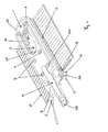
- the preferred embodiment of the burner according to the present invention comprises a first upper half shell and a second lower half shell indicated by 1 and 2 respectively.
- the two half shells 1, 2 are elongated and respectively have an upper face 101 and a lower face 102 and peripheral outer edges that can be mechanically and tightly connected to form a flat, box body which also has an elongated but substantially flat shape, and integrates, even in the exterior generic aspect, the two typical characteristics of tubular and flat burners respectively.
- Two corresponding ends 201, 202 of the upper half shell 1 and of the lower half shell 2 respectively are conformed in such a manner that, when the two half shells 1, 2 are joined together, they automatically form a flame arc forming head.
- the opposite corresponding ends 301, 302 of the shells 1, 2 are truncated and are conformed in such a manner as to form a venturi tube so that said head end is intended to form the inlet for supplying fuel and mixing it with comburent that is air in this case.
- Venturi tube extends beyond said head end of the burner with an end housing the fuel supplying nozzle (not shown in details) provided substantially at one or two combustion air inlet apertures.
- junction plane between the two half shells 1, 2 is substantially parallel both to the bottom and/or the underside and/or the top of the oven and to the outer faces 101, 102 of the two half shells 1, 2, the latter being therefore parallel. So the separator plane is practically oriented in the direction of the fuel/comburent mixture inlet and parallel to the two larger walls of the box flat body of the burner that is walls defined as the upper and lower walls indicated by 101 and 102.
- the two half shells 1, 2 are tightly joined together by bending continuous peripheral flanges that are subsequently riveted or drawn in order to form a channel whose outer side wall is opposite to the side wall of the half shell 1, which side wall has a row of aligned holes 501 for supplying the gas/air mixture to the channel, that forms the pilot burner. Therefore, the pilot burner is made of one piece with the burner body, whereby there is no need to provide a separate part to be attached to the tubular body, with all problems associated thereto.
- the pilot burner and the row of holes 501 have a substantially U-shaped extension, whose arched portion extends along the flame arc forming head and whose stems end substantially at the truncated ends 301, 302 of the two half shells particularly at a certain distance from said gas/air mixture inlet ends, considering the extension of the burner and so of the two half shells with the ending portion on the gas and air mixture inlet end intended to form the integrated venturi tube that will be described below.
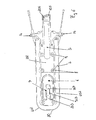
- Each side wall of the upper half shell 1 has an additional row of holes 601 with a larger diameter, which are provided at the flame arc forming head area and form the main gas/air mixture outlet holes.
- the two half shells are shaped at the air/gas mixture inlet end area in such a way to form the venturi tube wherein said mixture is produced. Therefore, in this case the half shells of the venturi tube are made of one piece as axial extensions of the half shells 1, 2 which form the box burner body, whereby, in the assembled condition, the venturi tube indicated by 5 is coaxial to the box burner body.
- the tubular body of the venturi tube, composed of the extensions of the two half shells 1, 2 has a substantially funnel-like shape, tapering in a direction opposite to the gas/air mixture inflow, and it extends beyond the corresponding end of the burner with an end 105 supporting the gas supplying nozzle (not shown in details) which has a pair of primary combustion air intake apertures 205.
- the venturi tube further has a tubular sleeve (not shown) which can slide axially along the venturi tube from a position in which it substantially completely closes said intake apertures 205 to a position in which it substantially completely opens them, thereby providing adjustment of the stoichiometric gas/air ratio.
- Said sleeve has a screw for axially locking it in the proper position.
- an half shell 1 has an outer peripheral flange 401 intended to form the outer, side wall of the channel which form the pilot supplying gas/air mixture acting for spreading the flame triggering the ignition which is generated by an igniter 16, whose end producing the spark is provided at the initial area of said channel on one side of the burner and in the end area thereof associated to gas/air mixture inlet.
- the flange 401 extends without interruptions about the outer burner perimeter from said initial end at the igniter 16 to a point which is diametrically opposite on the other side of the burner passing along the head end opposite to gas/air mixture inlet one and at which final end there is provided the sensible point of the flame detecting thermocouple 15.
- the flange 401 cooperates with a flange of the half shell 2 connected thereto by riveting and bending such to form a tight closing.
- the burner has a tab 3 for fastening it.
- the fastening tab 3 is made of one piece with the box burner body and it is provided at an aperture 4 of the box burner body passing through it. Such aperture 4 allows to easily reach the fastening tab 3 in order to tighten it by a screw or the like cooperating with an hole 103 in said fastening tab 3.
- the fastening tab 3 has an initial section 203 oriented transverse to the plane of the corresponding burner wall and it ends with a fastening section 303 oriented substantially parallel to the burner wall 101 and/or to the separator plane between the two half shells 1, 2.
- the fastening tab overlaps the plant of the burner and it extends by its fastening section 303 at a certain distance from the burner wall to which it is overlapped.
- the fastening tab 3 is composed of two shaped tongues that are obtained from the material of the aperture 4 of each of the two half shells respectively.
- the two tongues 701, 702 are pressed together and are correspondingly shaped to form the fastening tab, moreover perimetral edges of said tongues 701, 702 have perimetral flanges that tightly close the perimetral edges of the tongue by bending one upon the other and by pressing and/or by drawning.
- said flanges are provided also along edges delimiting apertures in the wall of the two half shells 1, 2 forming the through aperture 4 coinciding with said fastening tab and by means of which the two half shells are tightly joined together along said edge delimiting said through aperture 4.
- the fastening tab 3 achieves a U shape that aids in stiffening it. Moreover flanges bent and pressed together along edges aid in stiffening since they generate a sort of peripheral rib or tabs.
- Edges delimiting the through aperture 4 coinciding with the fastening tab 3 also generate a line abuting the two half shells acting like a spacing member strenghtening the flat box body of the burner in the intermediate area of its plant extension.
- the half shell 1 is shaped such to have a central depression at the outer side thereof corresponding to an inner projection in the direction of the opposite half shell 1.
- the central depression extends such to leave a perimetral band like a swelling extending without interruption along longitudinal sides and along the head end of the burner box body opposite to the gas and air mixture inlet end forming an U-shaped perimetral chamber supplying gas.
- said perimetral chamber distributing the gas/air mixture indicated by 802 ends at a certain distance from said head end projecting also beyond the final end of the venturi tube 5 on the side inside the box burner body, so the venturi tube enters to such an extent by its final gas/air mixture outlet end between ending sections of said U-shaped perimetral chamber 802.
- the rows of holes 502, and 602 are arranged substantially along the outer wall of the half shell 1 in the part thereof externally delimiting the U-shaped chamber 802 supplying gas/air mixture.
- a narrowed area is formed in the inner space of the box burner body at the central recess/projection of the half shell 1 since the corresponding wall of the half shell 1 does not follow the shape of said recess/projection of the half shell 2 except for a central shape composed of a central swelling of said half shell 1 provided in the wall 101 substantially coinciding with the outer recess and inner projection of the half shell 2 which has a depth that is smaller than the one of said outer recess and inner projection of the half shell 2. Therefore as shall be noted in section views the stems of the U-shaped perimetral chamber 602 communicate one with the other by an intermediate narrowing chamber that helps in balancing and making even the gas/air mixture pression inside said U-shaped chamber 602.
- the venturi tube 5 provided coaxial to the central median axis of the burner particularly leads at said narrowing chamber at a certain distance from the head end thereof on the side faced towards the gas/air mixture inlet and in a central position of the burner.
- the two opposite walls 1 and 2 suitably shaped in order to form said venturi tube, i.e. the two half shells thereof are in contact one with the other in order to avoid gas/air mixture flow to escape sideways while in the ending portion of the venturi tube entering inside the burner area corresponding to the central narrowing chamber T, the venturi tube is open sideways. Therefore such ending portion is made like a spout and side apertures along opposite side edges allow the gas/air mixture to pass towards ending portions of longitudinal stems of the perimetral U-shaped chamber 602.
- the burner has substantially the same transverse extension in the ending portion extending along the venturi tube 5 beyond the end of the narrowing chamber T and that sideways of the venturi tube the two walls 101 and 102 are pressed one against the other in order to make stiffening side tabs 11.
- the burner has a quite large plant shape in order to avoid larger burner walls to be deformed i.e. the upper and lower walls 101 and 102 there are provided spacing members 8 among them helping in strengthening the box body structure.
- Said spacers are advantageously composed of recesses of walls 101 and 102 or only one of these having a limited extension with respect to the total surface of said walls and forming mutual contacting areas inside the box body.
- the amount and distribution as well as the extension of these contacting areas or contacting islands 8 is determined by the plant size of the burner and that is width and length and it is selected such not to compromise the function of the central narrowing chamber indicated by T in section views.
- said contacting areas are provided coinciding with through holes 9 for fastening a reflecting shield or parabola 10.
- a reflecting shield or parabola 10 When the burner is composed of two separate half shells 1 and 2 as in the shown example the edges of said holes 9 are tightly closed according to the already previously described technique consisting in bending flanges along edges delimiting the holes and bend one upon the other.
- the parabola or reflecting shield 10 has a central area 110 adhering with one of the largest walls 101 or 102 of the box burner body at said holes 9 having fastening tabs 210 each fitting in a corresponding hole 9 and projecting beyond the opposite wall of the burner with a fastening end bend against said wall 101 thus causing the coupling between the parabola 10 and the burner.
- the central part of the parabola is adherent preferably to the burner wall having the central recess and perimetral swelling forming the perimetral U-shaped chamber 602, said central part of the parabola 10 being shaped complementary to said wall 102. All that produces a shape fit allowing to immediately, easily and quickly position the parabola and in addition it strengthenes its fastening in position to the burner.
- the central part of the parabola intended to adhere to the burner wall 102 has also an aperture 410 coinciding with the through aperture 4 of the box burner body and associated to the fastening tab 3.
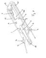
- the burner further includes a mounting 14 for supporting in a predetermined position a flame detecting thermocouple 15 and an igniter 16 of the burner.
- Mountings 14 are made as one piece with the burner and are composed of arm-like projections of the stiffening tabs 11 sideways of the intermediate portion of the venturi tube 5.
- Each mounting 14 ends with a pair of transverse tabs 114 wherein a hole 214 is provided which holes are coaxial one with respect to the other according to an axis having a direction inclined towards the central axis of the burner and towards the row of main gas/air mixture outlet holes 601.
- the igniter 16 and the thermocouple 15 are designed to be introduced axially to length in each of the coaxial holes 214.
- Position locking means for example an elastic clip 17 are provided for axially securing the thermocouple 15 and the igniter 16.
- Mountings 14 have a position and arrangement such that the thermocouple and igniter automatically have the proper arrangement with respect to the burner, while when assembling the thermocouple and the igniter only the axial position has to be adjusted, that is the distance of thermocouple and igniter ends from the burner in order to perfectly operate. By means of this arrangement it is easier to assemble the burner.
- mountings 14 are composed of extensions of both the half shells intended to overlap one with the other and are joined together by pressing and by drawing and/or bending flanges along perimetral edges of said extensions. Moreover, extensions of half shells 1, 2 forming mountings 14 are shaped such to form mutual spacing areas thus forming stiffenings as shown in figures by I.
- the embodiment shown and wherein the burner is composed of only two half shells mechanically and tightly joined together by common techniques for mechanically tightly joining metal half shells is particularly advantageous even if construction advantages of the burner there can be also with burners made by different manufacturing techniques.
- Each half shell is obtained by cutting and molding a sheet metal blank.
- the fastening tab is obtained as one piece by cutting the material intended to be removed in order to make apertures forming the through aperture 4 of the burner coinciding therewith. In this case the cutting is made only along two longitudinal edges of the aperture and along only one of the transverse edges.
- the two half shells as already described above are made such to have coinciding tabs in the area of one aperture intended to be overlapped one with the other forming the through aperture 4 and the fastening tab 3 of the burner, coinciding half shells of the venturi tube intended to form a venturi tube member 5, coinciding side extensions each one intended to form at least a mounting supporting an igniter and/or a thermocouple when they are mounted.
- one of the two half shells 2 is provided with the two rows of holes 501 and 601 and/or in case with the shaping for generating the perimetral U-shaped chamber distributing the gas/air mixture.
- the two half shells thus formed are fastened together and/or in case are also further partially shaped for example as regards intermediate spacers and/or fastening tab 3 and/or supporting arms 14 of the igniter and/or the shaping of the U-shaped parimetral chamber distributing the gas/air mixture and of the thermocouple by drawning and/or molding and/or bending peripheral flanges, while an outer peripheral flange of one of the two half shell is intended to form the outer side wall delimiting a channel spreading the ignition spark.
- the particular shape of the box body allows to obtain an optimum distribution of the gas/air mixture inside the burner in order to have optimum performances during the ignition and to generate an optimum and substantially even flow of the output gas/air mixture from main holes 601.
- the insertion of the venturi tube 5 as one piece inside the burner allows to limit the size of the burner, keeping the size of the flame unchanged relative to its distribution in the longitudinal direction of the burner.
- the manufacturing as one piece of the fastening tab and/or of the mountings of the thermocouple and/or igniter allow to limit costs and size and to make easier the fitting of the burner.
- the fact that said mountings have such housings for the igniter and/or the thermocouple to determine an automatic optimum positioning of the thermocouple and of the igniter leaving only a degree of freedom in the axial sliding direction of these members makes more easier the fitting of the burner.
- the through aperture at said tab allow to make two types of the burner to be applied one to the bottom of the oven and the other one to the top of it in order to act as a grill.
- the fastening tab 3 may be deformed in a way symmetrically opposite to the one shown in figures and that is in order to project outwardly on the burner side opposite with respect to the shown one.
- the substantial change is to vary the position of the fastening tab from a position offset with respect to the median plane to a position simmetricaly opposite with respect to said median plane of the burner box body.
Landscapes
- Engineering & Computer Science (AREA)
- Chemical & Material Sciences (AREA)
- Combustion & Propulsion (AREA)
- Mechanical Engineering (AREA)
- General Engineering & Computer Science (AREA)
- Gas Burners (AREA)
Applications Claiming Priority (2)
| Application Number | Priority Date | Filing Date | Title |
|---|---|---|---|
| IT000023A ITSV20050023A1 (it) | 2005-06-30 | 2005-06-30 | Bruciatore per forno o grill |
| EP06777291.3A EP1899643B1 (fr) | 2005-06-30 | 2006-06-09 | Bruleur de four ou de grill |
Related Parent Applications (3)
| Application Number | Title | Priority Date | Filing Date |
|---|---|---|---|
| EP06777291.3 Division | 2006-06-09 | ||
| EP06777291.3A Division EP1899643B1 (fr) | 2005-06-30 | 2006-06-09 | Bruleur de four ou de grill |
| EP06777291.3A Division-Into EP1899643B1 (fr) | 2005-06-30 | 2006-06-09 | Bruleur de four ou de grill |
Publications (3)
| Publication Number | Publication Date |
|---|---|
| EP2256408A2 true EP2256408A2 (fr) | 2010-12-01 |
| EP2256408A3 EP2256408A3 (fr) | 2014-11-12 |
| EP2256408B1 EP2256408B1 (fr) | 2016-03-23 |
Family
ID=36930305
Family Applications (2)
| Application Number | Title | Priority Date | Filing Date |
|---|---|---|---|
| EP06777291.3A Active EP1899643B1 (fr) | 2005-06-30 | 2006-06-09 | Bruleur de four ou de grill |
| EP10177896.7A Active EP2256408B1 (fr) | 2005-06-30 | 2006-06-09 | Brûleur de four ou de grill |
Family Applications Before (1)
| Application Number | Title | Priority Date | Filing Date |
|---|---|---|---|
| EP06777291.3A Active EP1899643B1 (fr) | 2005-06-30 | 2006-06-09 | Bruleur de four ou de grill |
Country Status (7)
| Country | Link |
|---|---|
| US (1) | US20080210217A1 (fr) |
| EP (2) | EP1899643B1 (fr) |
| BR (1) | BRPI0610752B1 (fr) |
| IT (1) | ITSV20050023A1 (fr) |
| MX (1) | MX2007016555A (fr) |
| RU (1) | RU2007148519A (fr) |
| WO (1) | WO2007003484A2 (fr) |
Cited By (1)
| Publication number | Priority date | Publication date | Assignee | Title |
|---|---|---|---|---|
| IT201600097603A1 (it) * | 2016-09-29 | 2018-03-29 | Actek S R L | Diffusore per forno |
Families Citing this family (22)
| Publication number | Priority date | Publication date | Assignee | Title |
|---|---|---|---|---|
| KR100829627B1 (ko) * | 2007-01-23 | 2008-05-16 | 엘지전자 주식회사 | 가열조리기기의 버너시스템 및 버너시스템의 연소유닛과연소유닛의 제조방법 |
| AU317314S (en) * | 2007-09-17 | 2007-12-20 | Shriro Australia Pty Ltd | A gas barbeque burner |
| US20090126716A1 (en) * | 2007-11-21 | 2009-05-21 | Geoglobal Partners, Llc | U-shaped burner for grill |
| CN101889171B (zh) * | 2008-06-23 | 2012-08-29 | 萨巴夫股份有限公司 | 烤炉用燃气燃烧器 |
| USD634578S1 (en) * | 2008-11-17 | 2011-03-22 | Wolfedale Engineering Limited | Combined shelf and console for a barbecue grill |
| USD618506S1 (en) * | 2009-02-16 | 2010-06-29 | Castfutura Spa | Burner |
| US20100242944A1 (en) * | 2009-03-31 | 2010-09-30 | Meco Corporation | Multi-burner head |
| US20110143293A1 (en) * | 2009-12-13 | 2011-06-16 | Kiosky Chung | Pilot Flame unit |
| RU2509264C1 (ru) * | 2009-12-17 | 2014-03-10 | Арчелык Аноним Ширкети | Духовка, содержащая горелку |
| TW201211463A (en) * | 2010-09-01 | 2012-03-16 | Pro Iroda Ind Inc | Combustion board |
| ITMI20111609A1 (it) * | 2011-09-07 | 2013-03-08 | Actek S R L | Bruciatore per forno o grill |
| BR112015024754A2 (pt) * | 2013-03-26 | 2017-07-18 | Electrolux Home Prod Inc | queimador em grelha para forno |
| US9504351B2 (en) * | 2013-10-11 | 2016-11-29 | Haler U.S. Appliance Solutions, Inc. | Double oven appliance |
| US9854938B2 (en) | 2014-05-30 | 2018-01-02 | Don Jellis | Grill and rotisserie apparatus |
| ITUA20161671A1 (it) * | 2016-03-15 | 2017-09-15 | Castfutura Spa | Bruciatore per forno perfezionato e apparato di cottura comprendente tale bruciatore |
| IT201600096554A1 (it) * | 2016-09-27 | 2018-03-27 | Actek S R L | Bruciatore per forno o grill |
| WO2018086942A1 (fr) | 2016-11-08 | 2018-05-17 | Arcelik Anonim Sirketi | Four comprenant un brûleur |
| IT201900003507A1 (it) * | 2019-03-11 | 2020-09-11 | Polidoro S P A | Sensore di temperatura perfezionato per bruciatore a gas e assieme di un tale sensore e bruciatore |
| CN117426680A (zh) * | 2020-05-13 | 2024-01-23 | 关隆股份有限公司 | 窑烤炉 |
| USD1005769S1 (en) | 2021-09-08 | 2023-11-28 | Newage Products Inc. | Oven |
| US12402631B2 (en) * | 2021-09-08 | 2025-09-02 | Newage Products Inc. | Oven |
| US12553613B2 (en) * | 2023-07-06 | 2026-02-17 | Haier Us Appliance Solutions, Inc. | Oven appliance and embossed heat shield for an oven appliance |
Family Cites Families (61)
| Publication number | Priority date | Publication date | Assignee | Title |
|---|---|---|---|---|
| USRE17438E (en) * | 1929-09-17 | Boyers | ||
| US1908668A (en) * | 1933-05-09 | hollman | ||
| US344987A (en) * | 1886-07-06 | redmayne | ||
| US1790739A (en) * | 1931-02-03 | Sylvania | ||
| US854491A (en) * | 1906-06-27 | 1907-05-21 | William Henry Haggerty | Fire-kindler. |
| US1038965A (en) * | 1911-07-26 | 1912-09-17 | American Stove Co | Gas-burner. |
| US1130984A (en) * | 1913-06-09 | 1915-03-09 | Adolph H Koch | Gas burner and mixer. |
| US1151188A (en) * | 1914-12-07 | 1915-08-24 | Thomas H Kelly | Gas-burner for ranges. |
| US1224157A (en) * | 1916-08-31 | 1917-05-01 | Detroit Stove Works | Gas-burner. |
| US1823460A (en) * | 1929-12-12 | 1931-09-15 | Methudy Automatic Lighter Co | Gas burner |
| US1995351A (en) * | 1931-01-21 | 1935-03-26 | Roper Corp Geo D | Oven burner support |
| US2011848A (en) * | 1931-08-10 | 1935-08-20 | John E Chambers | Gas stove |
| US2041310A (en) * | 1933-05-10 | 1936-05-19 | Walker & Pratt Mfg Co | Range |
| US2070111A (en) * | 1934-02-23 | 1937-02-09 | Charles V Blayney | Broiling device |
| US2102482A (en) * | 1936-08-07 | 1937-12-14 | Skoop A Corp | Burner mechanism for gaseous fuel stoves |
| US2154491A (en) * | 1937-08-23 | 1939-04-18 | John E Chambers | Stove |
| US2253178A (en) * | 1938-06-04 | 1941-08-19 | Roper Corp Geo D | Oven burner for gas ranges |
| US2235886A (en) * | 1938-11-16 | 1941-03-25 | Estate Stove Co | Stove |
| US2355216A (en) * | 1942-02-19 | 1944-08-08 | Milwaukee Gas Specialty Co | Pilot burner |
| US2560777A (en) * | 1945-01-26 | 1951-07-17 | Florence Stove Co | Sheet-metal oven gas burner |
| US2459879A (en) * | 1945-09-27 | 1949-01-25 | Christopher L Hardwick | Clamping means |
| US2539101A (en) * | 1946-05-03 | 1951-01-23 | Florence Stove Co | Sheet-metal top burner for gas cookstoves |
| US2582642A (en) * | 1950-05-23 | 1952-01-15 | Tappan Stove Co | Broiler burner and radiant screen for gas cooking ranges |
| US2720258A (en) * | 1953-11-25 | 1955-10-11 | Magic Chef Inc | Radiant gas burner |
| US2867207A (en) * | 1954-03-08 | 1959-01-06 | Roper Corp Geo D | Heat radiating means for broiler burners |
| US2879761A (en) * | 1954-04-15 | 1959-03-31 | Samuel Shapiro M | Barbecue grill grate |
| US3286762A (en) * | 1964-12-03 | 1966-11-22 | Robertshaw Controls Co | Combination pilot burner and thermocouple mount |
| US3322112A (en) * | 1965-04-13 | 1967-05-30 | Harper Wyman Co | Infrared gas burner |
| DE1918215U (de) * | 1965-04-22 | 1965-06-24 | Imp Werke G M B H | Allgasbrenner, insbesondere allgas-grillbrenner. |
| US3540258A (en) * | 1966-08-09 | 1970-11-17 | Robertshaw Controls Co | Burner construction and method and apparatus for making the same and the like |
| FR1500383A (fr) * | 1966-09-23 | 1967-11-03 | Rosieres Usines | Perfectionnement apporté au fonctionnement d'un brûleur de four par l'incorporation dans ce brûleur d'une veilleuse de sécurité à flamme bleue |
| FR1514654A (fr) * | 1966-12-07 | 1968-02-23 | Ferdinando Zoppas S P A | Procédé de construction d'un brûleur à gaz en tôle d'acier avec flamme pilote stabilisatrice, et brûleur à gaz construit suivant ce procédé et destiné à un type quelconque de four pour appareils domestiques de cuisson |
| US3768131A (en) * | 1970-05-15 | 1973-10-30 | Robertshaw Controls Co | Burner construction and method of making the same or the like |
| US3754854A (en) * | 1971-06-26 | 1973-08-28 | Junkers & Co | Device for use with gas appliances |
| US3758265A (en) * | 1972-05-15 | 1973-09-11 | Vaillant Joh Kg | Gas burner of sheet metal |
| US3858811A (en) * | 1973-07-02 | 1975-01-07 | Harper Wyman Co | Gas burner |
| US3922138A (en) * | 1974-08-19 | 1975-11-25 | Athens Stove Works Inc | Gas range top burner |
| US3959866A (en) * | 1974-08-19 | 1976-06-01 | Athens Stove Works, Inc. | Method of making a gas range top burner |
| JPS5246536A (en) * | 1975-10-09 | 1977-04-13 | Matsushita Electric Ind Co Ltd | Wire netting type gas burner |
| US4416249A (en) * | 1976-12-10 | 1983-11-22 | Reynolds Howard R | Oven burner radiant |
| JPS55116016A (en) * | 1980-02-12 | 1980-09-06 | Matsushita Electric Ind Co Ltd | Manufacture of pipe burner |
| EP0055911A3 (fr) * | 1981-01-02 | 1982-12-15 | Ewarts Limited | Brûleurs à gaz |
| US4485972A (en) * | 1981-10-15 | 1984-12-04 | Marquette Tool And Die Company | Burner for cooking grills |
| US4418456A (en) * | 1981-11-04 | 1983-12-06 | Robertshaw Controls Company | Tubular burner construction and method of making the same |
| GB8333399D0 (en) * | 1983-12-15 | 1984-01-25 | Baxi Partnership Ltd | Gas-fired appliances |
| US4628900A (en) * | 1985-10-30 | 1986-12-16 | Arndt H Chandler | Radiant heater |
| US5035609A (en) * | 1989-12-26 | 1991-07-30 | Robertshaw Controls Company | Jet burner construction, heating apparatus utilizing the jet burner construction and methods of making the same |
| US4986254A (en) * | 1990-07-02 | 1991-01-22 | Greene Manufacturing Co. | Bar burner |
| US5244382A (en) * | 1991-12-10 | 1993-09-14 | Robertshaw Controls Company | Jet burner construction, heating apparatus utilizing the jet burner construction and methods of making the same |
| US5421319A (en) * | 1993-08-13 | 1995-06-06 | W. C. Bradley Company | Heating system for barbecue grills and other gas appliances |
| GB2281963B (en) * | 1993-09-16 | 1997-11-05 | Stoves Ltd | Improvements in and relating to gaseous fuel burners |
| US5711663A (en) * | 1994-08-14 | 1998-01-27 | Sunbeam Porducts, Inc. | Burner |
| US5511973A (en) * | 1994-12-22 | 1996-04-30 | Whirlpool Corporation | Ignition cover and venturi mounting clip |
| IT1311226B1 (it) * | 1999-06-01 | 2002-03-04 | Timoteo Pezzutti | Bruciatore atmosferico a gas di tipo longitudinale conelemento radiante generante condotti laterali di stabilizzazione |
| US6283114B1 (en) * | 1999-08-13 | 2001-09-04 | Sunbeam Products, Inc. | Tented gas burner for grill |
| USD470721S1 (en) * | 2001-11-20 | 2003-02-25 | Grand Hall Enterprise Co., Ltd. | Burner |
| ITSV20020015A1 (it) * | 2002-04-19 | 2003-10-20 | Cast Srl | Bruciatore per forno o grill tubo venturi staffa di sopporto di una termocoppia e/o di una candeletta di accensione e procedimento per la fab |
| US6699036B2 (en) * | 2002-05-06 | 2004-03-02 | Weber-Stephen Products Company | Curvilinear burner tube |
| US20060081237A1 (en) * | 2004-10-14 | 2006-04-20 | Kiosky Chung | Stove body for large-scale barbecue stove |
| USD548007S1 (en) * | 2006-11-23 | 2007-08-07 | Kiosky Chung | Burner for barbecue grill |
| USD618506S1 (en) * | 2009-02-16 | 2010-06-29 | Castfutura Spa | Burner |
-
2005
- 2005-06-30 IT IT000023A patent/ITSV20050023A1/it unknown
-
2006
- 2006-06-09 RU RU2007148519/06A patent/RU2007148519A/ru not_active Application Discontinuation
- 2006-06-09 WO PCT/EP2006/063068 patent/WO2007003484A2/fr not_active Ceased
- 2006-06-09 BR BRPI0610752-4A patent/BRPI0610752B1/pt not_active IP Right Cessation
- 2006-06-09 US US11/993,883 patent/US20080210217A1/en not_active Abandoned
- 2006-06-09 EP EP06777291.3A patent/EP1899643B1/fr active Active
- 2006-06-09 MX MX2007016555A patent/MX2007016555A/es unknown
- 2006-06-09 EP EP10177896.7A patent/EP2256408B1/fr active Active
Cited By (1)
| Publication number | Priority date | Publication date | Assignee | Title |
|---|---|---|---|---|
| IT201600097603A1 (it) * | 2016-09-29 | 2018-03-29 | Actek S R L | Diffusore per forno |
Also Published As
| Publication number | Publication date |
|---|---|
| US20080210217A1 (en) | 2008-09-04 |
| WO2007003484A2 (fr) | 2007-01-11 |
| WO2007003484A3 (fr) | 2008-01-10 |
| BRPI0610752B1 (pt) | 2019-04-30 |
| BRPI0610752A2 (pt) | 2010-12-07 |
| EP2256408B1 (fr) | 2016-03-23 |
| ITSV20050023A1 (it) | 2007-01-01 |
| RU2007148519A (ru) | 2009-08-10 |
| EP1899643B1 (fr) | 2015-10-21 |
| EP2256408A3 (fr) | 2014-11-12 |
| MX2007016555A (es) | 2008-03-04 |
| EP1899643A2 (fr) | 2008-03-19 |
Similar Documents
| Publication | Publication Date | Title |
|---|---|---|
| EP2256408B1 (fr) | Brûleur de four ou de grill | |
| US7506645B2 (en) | Oven or grill burner, venturi tube, mounting for a thermocouple and/or an igniter, and process for fabricating said burner | |
| EP3299716B1 (fr) | Brûleur pour appareil à gaz | |
| US2348011A (en) | Sheet metal gas burner | |
| EP0615597A1 (fr) | Structure de bruleur a jet, appareil de chauffage utilisant ladite structure et procedes de fabrication associes | |
| CN112944345A (zh) | 用于燃气烤架的燃烧器管 | |
| AU719762B2 (en) | Two piece multiple inshot-type fuel burner structure | |
| EP2307800B1 (fr) | Brûleur à gaz pour fours | |
| US5316470A (en) | Jet burner construction heating apparatus utilizing the jet burner construction and methods of making the same | |
| CN115143462B (zh) | 燃烧器和燃气灶 | |
| US5445519A (en) | Jet burner construction heating apparatus utilizing the jet burner construction and methods of making the same | |
| HU186931B (en) | Atmospheric mixed gas burner advantageously for gas-fired household appliances | |
| EP2776760B1 (fr) | Brûleur à gaz | |
| US3472602A (en) | Radiant gas burner | |
| EP0793058A2 (fr) | Tube mélangeur pour brûleur à gaz | |
| CN222937808U (zh) | 喷嘴组件及燃气灶 | |
| CN222798986U (zh) | 燃烧器及烹饪器具 | |
| EP0028102B1 (fr) | Brûleur à gaz | |
| CN118669832A (zh) | 燃烧器及烹饪器具 | |
| CN118669837A (zh) | 燃烧器及烹饪器具 | |
| US20110143293A1 (en) | Pilot Flame unit | |
| CN121322950A (zh) | 燃烧器及烹饪器具 | |
| KR0138407Y1 (ko) | 가스레인지의 파이롯트버너 어셈블리의 구조 | |
| GB1597221A (en) | Gas-fired burner | |
| CN114321916A (zh) | 上进风式燃烧器及灶具 |
Legal Events
| Date | Code | Title | Description |
|---|---|---|---|
| PUAI | Public reference made under article 153(3) epc to a published international application that has entered the european phase |
Free format text: ORIGINAL CODE: 0009012 |
|
| AC | Divisional application: reference to earlier application |
Ref document number: 1899643 Country of ref document: EP Kind code of ref document: P |
|
| AK | Designated contracting states |
Kind code of ref document: A2 Designated state(s): AT BE BG CH CY CZ DE DK EE ES FI FR GB GR HU IE IS IT LI LT LU LV MC NL PL PT RO SE SI SK TR |
|
| RAP1 | Party data changed (applicant data changed or rights of an application transferred) |
Owner name: CASTFUTURA S.P.A. |
|
| PUAL | Search report despatched |
Free format text: ORIGINAL CODE: 0009013 |
|
| AK | Designated contracting states |
Kind code of ref document: A3 Designated state(s): AT BE BG CH CY CZ DE DK EE ES FI FR GB GR HU IE IS IT LI LT LU LV MC NL PL PT RO SE SI SK TR |
|
| RIC1 | Information provided on ipc code assigned before grant |
Ipc: F23D 14/10 20060101AFI20141009BHEP Ipc: F24C 3/04 20060101ALI20141009BHEP Ipc: F24C 3/08 20060101ALI20141009BHEP |
|
| 17P | Request for examination filed |
Effective date: 20150511 |
|
| GRAP | Despatch of communication of intention to grant a patent |
Free format text: ORIGINAL CODE: EPIDOSNIGR1 |
|
| INTG | Intention to grant announced |
Effective date: 20150928 |
|
| GRAS | Grant fee paid |
Free format text: ORIGINAL CODE: EPIDOSNIGR3 |
|
| GRAA | (expected) grant |
Free format text: ORIGINAL CODE: 0009210 |
|
| AC | Divisional application: reference to earlier application |
Ref document number: 1899643 Country of ref document: EP Kind code of ref document: P |
|
| AK | Designated contracting states |
Kind code of ref document: B1 Designated state(s): AT BE BG CH CY CZ DE DK EE ES FI FR GB GR HU IE IS IT LI LT LU LV MC NL PL PT RO SE SI SK TR |
|
| REG | Reference to a national code |
Ref country code: GB Ref legal event code: FG4D |
|
| REG | Reference to a national code |
Ref country code: CH Ref legal event code: EP |
|
| REG | Reference to a national code |
Ref country code: AT Ref legal event code: REF Ref document number: 783535 Country of ref document: AT Kind code of ref document: T Effective date: 20160415 |
|
| REG | Reference to a national code |
Ref country code: IE Ref legal event code: FG4D |
|
| REG | Reference to a national code |
Ref country code: DE Ref legal event code: R096 Ref document number: 602006048394 Country of ref document: DE |
|
| REG | Reference to a national code |
Ref country code: LT Ref legal event code: MG4D |
|
| REG | Reference to a national code |
Ref country code: NL Ref legal event code: MP Effective date: 20160323 |
|
| PG25 | Lapsed in a contracting state [announced via postgrant information from national office to epo] |
Ref country code: FI Free format text: LAPSE BECAUSE OF FAILURE TO SUBMIT A TRANSLATION OF THE DESCRIPTION OR TO PAY THE FEE WITHIN THE PRESCRIBED TIME-LIMIT Effective date: 20160323 Ref country code: GR Free format text: LAPSE BECAUSE OF FAILURE TO SUBMIT A TRANSLATION OF THE DESCRIPTION OR TO PAY THE FEE WITHIN THE PRESCRIBED TIME-LIMIT Effective date: 20160624 |
|
| REG | Reference to a national code |
Ref country code: AT Ref legal event code: MK05 Ref document number: 783535 Country of ref document: AT Kind code of ref document: T Effective date: 20160323 |
|
| PG25 | Lapsed in a contracting state [announced via postgrant information from national office to epo] |
Ref country code: LT Free format text: LAPSE BECAUSE OF FAILURE TO SUBMIT A TRANSLATION OF THE DESCRIPTION OR TO PAY THE FEE WITHIN THE PRESCRIBED TIME-LIMIT Effective date: 20160323 Ref country code: NL Free format text: LAPSE BECAUSE OF FAILURE TO SUBMIT A TRANSLATION OF THE DESCRIPTION OR TO PAY THE FEE WITHIN THE PRESCRIBED TIME-LIMIT Effective date: 20160323 Ref country code: SE Free format text: LAPSE BECAUSE OF FAILURE TO SUBMIT A TRANSLATION OF THE DESCRIPTION OR TO PAY THE FEE WITHIN THE PRESCRIBED TIME-LIMIT Effective date: 20160323 Ref country code: LV Free format text: LAPSE BECAUSE OF FAILURE TO SUBMIT A TRANSLATION OF THE DESCRIPTION OR TO PAY THE FEE WITHIN THE PRESCRIBED TIME-LIMIT Effective date: 20160323 |
|
| PG25 | Lapsed in a contracting state [announced via postgrant information from national office to epo] |
Ref country code: EE Free format text: LAPSE BECAUSE OF FAILURE TO SUBMIT A TRANSLATION OF THE DESCRIPTION OR TO PAY THE FEE WITHIN THE PRESCRIBED TIME-LIMIT Effective date: 20160323 Ref country code: PL Free format text: LAPSE BECAUSE OF FAILURE TO SUBMIT A TRANSLATION OF THE DESCRIPTION OR TO PAY THE FEE WITHIN THE PRESCRIBED TIME-LIMIT Effective date: 20160323 Ref country code: IS Free format text: LAPSE BECAUSE OF FAILURE TO SUBMIT A TRANSLATION OF THE DESCRIPTION OR TO PAY THE FEE WITHIN THE PRESCRIBED TIME-LIMIT Effective date: 20160723 |
|
| PG25 | Lapsed in a contracting state [announced via postgrant information from national office to epo] |
Ref country code: AT Free format text: LAPSE BECAUSE OF FAILURE TO SUBMIT A TRANSLATION OF THE DESCRIPTION OR TO PAY THE FEE WITHIN THE PRESCRIBED TIME-LIMIT Effective date: 20160323 Ref country code: ES Free format text: LAPSE BECAUSE OF FAILURE TO SUBMIT A TRANSLATION OF THE DESCRIPTION OR TO PAY THE FEE WITHIN THE PRESCRIBED TIME-LIMIT Effective date: 20160323 Ref country code: PT Free format text: LAPSE BECAUSE OF FAILURE TO SUBMIT A TRANSLATION OF THE DESCRIPTION OR TO PAY THE FEE WITHIN THE PRESCRIBED TIME-LIMIT Effective date: 20160725 Ref country code: CZ Free format text: LAPSE BECAUSE OF FAILURE TO SUBMIT A TRANSLATION OF THE DESCRIPTION OR TO PAY THE FEE WITHIN THE PRESCRIBED TIME-LIMIT Effective date: 20160323 Ref country code: RO Free format text: LAPSE BECAUSE OF FAILURE TO SUBMIT A TRANSLATION OF THE DESCRIPTION OR TO PAY THE FEE WITHIN THE PRESCRIBED TIME-LIMIT Effective date: 20160323 Ref country code: SK Free format text: LAPSE BECAUSE OF FAILURE TO SUBMIT A TRANSLATION OF THE DESCRIPTION OR TO PAY THE FEE WITHIN THE PRESCRIBED TIME-LIMIT Effective date: 20160323 |
|
| PG25 | Lapsed in a contracting state [announced via postgrant information from national office to epo] |
Ref country code: BE Free format text: LAPSE BECAUSE OF FAILURE TO SUBMIT A TRANSLATION OF THE DESCRIPTION OR TO PAY THE FEE WITHIN THE PRESCRIBED TIME-LIMIT Effective date: 20160323 |
|
| REG | Reference to a national code |
Ref country code: DE Ref legal event code: R097 Ref document number: 602006048394 Country of ref document: DE |
|
| REG | Reference to a national code |
Ref country code: DE Ref legal event code: R119 Ref document number: 602006048394 Country of ref document: DE |
|
| PLBE | No opposition filed within time limit |
Free format text: ORIGINAL CODE: 0009261 |
|
| STAA | Information on the status of an ep patent application or granted ep patent |
Free format text: STATUS: NO OPPOSITION FILED WITHIN TIME LIMIT |
|
| PG25 | Lapsed in a contracting state [announced via postgrant information from national office to epo] |
Ref country code: DK Free format text: LAPSE BECAUSE OF FAILURE TO SUBMIT A TRANSLATION OF THE DESCRIPTION OR TO PAY THE FEE WITHIN THE PRESCRIBED TIME-LIMIT Effective date: 20160323 Ref country code: MC Free format text: LAPSE BECAUSE OF FAILURE TO SUBMIT A TRANSLATION OF THE DESCRIPTION OR TO PAY THE FEE WITHIN THE PRESCRIBED TIME-LIMIT Effective date: 20160323 |
|
| REG | Reference to a national code |
Ref country code: CH Ref legal event code: PL |
|
| PG25 | Lapsed in a contracting state [announced via postgrant information from national office to epo] |
Ref country code: BG Free format text: LAPSE BECAUSE OF FAILURE TO SUBMIT A TRANSLATION OF THE DESCRIPTION OR TO PAY THE FEE WITHIN THE PRESCRIBED TIME-LIMIT Effective date: 20160623 |
|
| 26N | No opposition filed |
Effective date: 20170102 |
|
| GBPC | Gb: european patent ceased through non-payment of renewal fee |
Effective date: 20160623 |
|
| REG | Reference to a national code |
Ref country code: IE Ref legal event code: MM4A |
|
| REG | Reference to a national code |
Ref country code: FR Ref legal event code: ST Effective date: 20170228 |
|
| PG25 | Lapsed in a contracting state [announced via postgrant information from national office to epo] |
Ref country code: LI Free format text: LAPSE BECAUSE OF NON-PAYMENT OF DUE FEES Effective date: 20160630 Ref country code: DE Free format text: LAPSE BECAUSE OF NON-PAYMENT OF DUE FEES Effective date: 20170103 Ref country code: FR Free format text: LAPSE BECAUSE OF NON-PAYMENT OF DUE FEES Effective date: 20160630 Ref country code: CH Free format text: LAPSE BECAUSE OF NON-PAYMENT OF DUE FEES Effective date: 20160630 |
|
| PG25 | Lapsed in a contracting state [announced via postgrant information from national office to epo] |
Ref country code: SI Free format text: LAPSE BECAUSE OF FAILURE TO SUBMIT A TRANSLATION OF THE DESCRIPTION OR TO PAY THE FEE WITHIN THE PRESCRIBED TIME-LIMIT Effective date: 20160323 Ref country code: IE Free format text: LAPSE BECAUSE OF NON-PAYMENT OF DUE FEES Effective date: 20160609 Ref country code: GB Free format text: LAPSE BECAUSE OF NON-PAYMENT OF DUE FEES Effective date: 20160623 |
|
| PG25 | Lapsed in a contracting state [announced via postgrant information from national office to epo] |
Ref country code: CY Free format text: LAPSE BECAUSE OF FAILURE TO SUBMIT A TRANSLATION OF THE DESCRIPTION OR TO PAY THE FEE WITHIN THE PRESCRIBED TIME-LIMIT Effective date: 20160323 Ref country code: HU Free format text: LAPSE BECAUSE OF FAILURE TO SUBMIT A TRANSLATION OF THE DESCRIPTION OR TO PAY THE FEE WITHIN THE PRESCRIBED TIME-LIMIT; INVALID AB INITIO Effective date: 20060609 |
|
| PG25 | Lapsed in a contracting state [announced via postgrant information from national office to epo] |
Ref country code: LU Free format text: LAPSE BECAUSE OF NON-PAYMENT OF DUE FEES Effective date: 20160609 |
|
| PGFP | Annual fee paid to national office [announced via postgrant information from national office to epo] |
Ref country code: TR Payment date: 20240531 Year of fee payment: 19 |
|
| PGFP | Annual fee paid to national office [announced via postgrant information from national office to epo] |
Ref country code: IT Payment date: 20240530 Year of fee payment: 19 |
|
| PG25 | Lapsed in a contracting state [announced via postgrant information from national office to epo] |
Ref country code: IT Free format text: LAPSE BECAUSE OF NON-PAYMENT OF DUE FEES Effective date: 20250609 |