EP2256458A1 - Linienerzeuger - Google Patents
Linienerzeuger Download PDFInfo
- Publication number
- EP2256458A1 EP2256458A1 EP10163168A EP10163168A EP2256458A1 EP 2256458 A1 EP2256458 A1 EP 2256458A1 EP 10163168 A EP10163168 A EP 10163168A EP 10163168 A EP10163168 A EP 10163168A EP 2256458 A1 EP2256458 A1 EP 2256458A1
- Authority
- EP
- European Patent Office
- Prior art keywords
- lens
- line
- axis
- light
- laser diode
- Prior art date
- Legal status (The legal status is an assumption and is not a legal conclusion. Google has not performed a legal analysis and makes no representation as to the accuracy of the status listed.)
- Ceased
Links
Images


Classifications
-
- G—PHYSICS
- G01—MEASURING; TESTING
- G01C—MEASURING DISTANCES, LEVELS OR BEARINGS; SURVEYING; NAVIGATION; GYROSCOPIC INSTRUMENTS; PHOTOGRAMMETRY OR VIDEOGRAMMETRY
- G01C15/00—Surveying instruments or accessories not provided for in groups G01C1/00 - G01C13/00
- G01C15/002—Active optical surveying means
- G01C15/004—Reference lines, planes or sectors
-
- G—PHYSICS
- G02—OPTICS
- G02B—OPTICAL ELEMENTS, SYSTEMS OR APPARATUS
- G02B19/00—Condensers, e.g. light collectors or similar non-imaging optics
- G02B19/0004—Condensers, e.g. light collectors or similar non-imaging optics characterised by the optical means employed
- G02B19/0009—Condensers, e.g. light collectors or similar non-imaging optics characterised by the optical means employed having refractive surfaces only
- G02B19/0014—Condensers, e.g. light collectors or similar non-imaging optics characterised by the optical means employed having refractive surfaces only at least one surface having optical power
-
- G—PHYSICS
- G02—OPTICS
- G02B—OPTICAL ELEMENTS, SYSTEMS OR APPARATUS
- G02B19/00—Condensers, e.g. light collectors or similar non-imaging optics
- G02B19/0033—Condensers, e.g. light collectors or similar non-imaging optics characterised by the use
- G02B19/0047—Condensers, e.g. light collectors or similar non-imaging optics characterised by the use for use with a light source
- G02B19/0052—Condensers, e.g. light collectors or similar non-imaging optics characterised by the use for use with a light source the light source comprising a laser diode
-
- G—PHYSICS
- G02—OPTICS
- G02B—OPTICAL ELEMENTS, SYSTEMS OR APPARATUS
- G02B27/00—Optical systems or apparatus not provided for by any of the groups G02B1/00 - G02B26/00, G02B30/00
- G02B27/09—Beam shaping, e.g. changing the cross-sectional area, not otherwise provided for
- G02B27/0938—Using specific optical elements
- G02B27/095—Refractive optical elements
- G02B27/0955—Lenses
- G02B27/0966—Cylindrical lenses
-
- G—PHYSICS
- G02—OPTICS
- G02B—OPTICAL ELEMENTS, SYSTEMS OR APPARATUS
- G02B27/00—Optical systems or apparatus not provided for by any of the groups G02B1/00 - G02B26/00, G02B30/00
- G02B27/18—Optical systems or apparatus not provided for by any of the groups G02B1/00 - G02B26/00, G02B30/00 for optical projection, e.g. combination of mirror and condenser and objective
- G02B27/20—Optical systems or apparatus not provided for by any of the groups G02B1/00 - G02B26/00, G02B30/00 for optical projection, e.g. combination of mirror and condenser and objective for imaging minute objects, e.g. light-pointer
Definitions
- the present invention relates to a line generator using a light source such as a laser diode.
- line generators using light sources such as laser diodes, light emitting diodes, and optical fibers are used for setting fiducial lines for positioning, step height measurement and detection of defects.
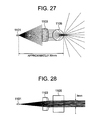
- Fig. 27 and Fig. 28 illustrate an example of configurations of conventional line generators.
- the line generator includes a laser diode light source 1101, a collimating lens having rotation symmetry 1103 and a rod lens 1105.
- Fig, 27 shows a cross sectional view in the vertical direction (fast-axis (FA) direction) of the laser diode light source 1101 while
- Fig, 28 shows a cross sectional view in the horizontal direction (slow-axis (SA) direction) of the laser diode light source 1101.
- FA fast-axis
- SA slow-axis
- light emitted by the laser diode light source 1101 is collimated by the collimating lens having rotation symmetry 1103 in the SA direction to generate a light beam having a width of 3 millimeters.
- the width of the light beam after the collimation is that of the line generated by the line generator.
- the light emitted by the laser diode light source 1101 is collimated by the collimating lens having rotation symmetry 1103 in the FA direction to generate a light beam having a width of approximately 6 millimeters.
- the light After being collimated by the collimating lens having rotation symmetry 1103, the light is diverged in the FA direction by the rod lens 1105 to generate the line.
- the size of the collimating lens 1103 is limited, only a part of the light which has become approximately 10 millimeter wide in the FA direction is utilized. As a result, maximum light utilizing efficiency is approximately 60 %. Further, although a wide diverging angle can be easily obtained, brightness along the line cannot be controlled.
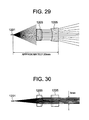
- Fig. 29 and Fig. 30 illustrate another example of configurations of conventional line generators.
- the line generator includes a laser diode light source 1201, a collimating lens having rotation symmetry 1203 and a cylindrical lens 1205.
- Fig, 29 shows a cross sectional view in the vertical direction (fast-axis (FA) direction) of the laser diode light source 1201 while
- Fig. 30 shows a cross sectional view in the horizontal direction (slow-axis (SA) direction) of the laser diode light source 1201.
- SA slow-axis
- the width of the light beam after the collimation is that of the line generated by the line generator.
- the light emitted by the laser diode light source 1201 is collimated by the collimating lens having rotation symmetry 1203 in the FA direction to generate a light beam having a width of approximately 6 millimeters.
- the light After being collimated by the collimating lens having rotation symmetry 1203, the light is diverged in the FA direction by the cylindrical lens 1205 to generate the line.
- the size of the collimating lens 1203 is limited, only a part of the light which has become approximately 10 millimeter wide in the FA direction is used. As a result, maximum light utilizing efficiency is approximately 60 %.
- Brightness along the line can be arbitrarily controlled by adjusting a shape of the optical surface of the cylindrical lens 1205.
- a tangential angle of the cylindrical shape can hardly be enlarged, and therefore a wide diverging angle can hardly be obtained.
- the light beam is designed to be focused at a position of a certain distance such that brightness along the line is made uniform. Accordingly, when the collimating lens 1203 is adjusted for focusing, brightness along the line will deviate from the designed value.
- a line generator includes a light source, a first lens group, and a second lens group.
- An optical axis is set to a path of a light beam which travels orthogonal to incidence surfaces of both the first and second lens groups and the first lens group is configured such that light beams from the light source are not collimated in a first direction in a plane orthogonal to the optical axis and are collimated or focused only in a second direction orthogonal to the first direction in the plane orthogonal to the optical axis and the second lens group is configured such that the light beams which have passed through the first group form a line.
- a lens group means one or plural lenses which has a predetermined function as the whole.
- a width of the line can be determined by adjusting shapes of optical surfaces of the first lens group while brightness distribution along the line can be arbitrarily adjusted by adjusting shapes of optical surfaces of the second lens group.
- light is collimated or focused only in one direction (a direction of width of the line) by the first lens group, and therefore a wide diverging angle can be obtained by the second group lens. Further, most portion of the light which has traveled thorough the first group lens enters the second group lens, and therefore light utilizing efficiency becomes higher.
- At least one of the first lens group and the second lens group is provided with a mechanism for adjustment of position along the optical axis.
- the focal position of the line can be easily adjusted while brightness distribution along the line is kept unchanged, by adjusting a position of the first lens group along the optical axis. Further, when one of the laser diode light sources light emitting conditions of which varies from one to another is used as the laser diode light source, brightness distribution along the line can be kept constant while the focal position is maintained by adjusting a position of the second lens along the optical axis.
- the light source is a laser diode and the first direction is set to the vertical direction (first-axis direction) of the laser diode and the second direction is set to the horizontal direction (slow-axis direction) of the laser diode.
- the FA direction is set to width direction of the line, and therefore a more compact line generator can be obtained.
- the light source is a laser diode and the second direction is set to the vertical direction (first-axis direction) of the laser diode and the first direction is set to the horizontal direction (slow-axis direction) of the laser diode.
- the SA direction is set to width direction of the line, and therefore a wider diverging angle can be obtained.
- At least one surface of the first and second lens groups is a free form surface which is symmetric with respect to the first direction and the second direction and a focal length in the first direction around the center differs from a focal length in the first direction at the periphery.
- collimating performance can be improved. More specifically, light can be focused in a narrower line or light can be focused on any surface as a line.
- a line generator according to an embodiment of the present invention is further provided with a phase plate having at least one free form surface.
- an optical element including a free form surface that is difficult to produce can be produced independently of lenses and therefore the producing process is simplified.
- to collimate also means “to focus light at a distant point”.
- Materials of lenses can be selected according to applications. Plastics are resistant to breaking and can be molded into complicated shapes at low costs. Glasses have coefficients of thermal expansion smaller than those of plastics and more heat-resistant than plastics, and therefore less insensitive to changes in surrounding environments and more reliable than plastics.
- Figs. 1 and 2 illustrate the configuration of a line generator according to Example 1 of the present invention.
- the line generator includes a laser diode light source 101, a first lens 103 which is a cylindrical lens and a second lens 105 which is a cylindrical lens.
- Fig. 1 shows a cross sectional view in the vertical direction (fast-axis (FA) direction) of the laser diode light source 101 while
- Fig. 2 shows a cross sectional view in the horizontal direction (slow-axis (SA) direction) of the laser diode light source 101.
- FA fast-axis
- SA slow-axis
- the width of the light beam after the collimation is that of the line generated by the line generator. Since the first lens 103 is a cylindrical one, the light is not collimated in the SA direction. The light collimated in the FA direction by the first lens 103 is diverged in the SA direction by the second lens 105 to generate the line.
- the light In the SA direction the light is not collimated by the first lens 103 and the diverged light is further diverged by the second lens 105. In other words, the light is not collimated in the SA direction in the present example. Accordingly, a diverging angle wider than those of conventional type line generators can be obtained. Further, most portion of the light which has traveled thorough the first lens 103 enters the second lens 105, and therefore light utilizing efficiency is 90% or more.
- brightness along the line can be made uniform or brightness at any portion can be increased.
- the first lens 103 is used to determine a width of the line while the second lens 105 is used to generate the line which has a desired brightness distribution along it.
- function of the first lens 103 and that of the second lens 105 are clearly separated from each other.
- the configuration in which the FA direction is set to the direction of the width of the line has the following advantage.
- the diverging angle in the FA direction is larger than that in the SA direction, and therefore a sufficient width of the line can be obtained with a short optical path length. This allows downsizing of the optical system.
- Table 1 shows data of the optical system of the line generator according to Example 1.
- the value entered at the cross point of the row labeled "light source” and the column labeled "surface interval” indicates an interval between the light source and the first lens.
- the value entered at the cross point of the row labeled "2" and the column labeled "surface interval” indicates a thickness of the first lens.
- the value entered at the cross point of the row labeled "3" and the column labeled "surface interval” indicates an interval between the first lens and the second lens.
- the value entered at the cross point of the row labeled "4" and the column labeled "surface interval” indicates a thickness of the second lens. Unit of length in Table 1 and the tables described below is millimeter. Table 1 Surface No.
- the optical surfaces of the first lens are represented by the following expressions.
- ⁇ 2 i represents correcting coefficients.
- Table 2 shows coefficients or constants in the expressions representing the second and third surfaces.
- Table 2 Second surface Third surface R 1.820144 infinity k -2.571631 0 a 4 5.85685x10 -6 0 ⁇ 6 2.113507x10 -7 0
- the optical surfaces of the second lens are represented by the following expressions.
- Table 3 shows coefficients or constants in the expressions representing the fourth and fifth surfaces.
- Table 3 Fourth surface Fifth surface a 2 -0.844902 0 a 4 0.359297 0 ⁇ 6 -0.099127 0 ⁇ 8 -0.012041 0 ⁇ 10 0.021224 0 ⁇ 12 -5.281427x10 -3 0
- Fig. 3 illustrates performance of the line generator according to Example 1.
- the horizontal axis of Fig. 3 represents distance between an arbitrary point on the line and the point of the intersection of the line and the optical axis.
- the vertical axis represents relative intensity of light at the arbitrary point.
- the illuminated surface is 1000 mm away from the light source and perpendicular to the optical axis. Brightness along the line on the illuminated surface is substantially uniform.
- parameters of the fourth surface should be determined appropriately.
- Figs. 4 and 5 illustrate the configuration of a line generator according to Example 2 of the present invention.
- the line generator includes a laser diode light source 201, a first lens 203 which is a cylindrical lens and a second lens 205 which is a cylindrical lens.
- Fig. 4 shows a cross sectional view in the vertical direction (fast-axis (FA) direction) of the laser diode light source 201 while
- Fig. 5 shows a cross sectional view in the horizontal direction (slow-axis (SA) direction) of the laser diode light source 201.
- FA fast-axis
- SA slow-axis
- light emitted by the laser diode light source 201 is collimated by the first lens 203 in the SA direction to generate a light beam having a width of 3 millimeters.
- the width of the light beam after the collimation is that of the line generated by the line generator. Since the first lens 203 is a cylindrical one, the light is not collimated in the FA direction. The light collimated in the SA direction by the first lens 203 is diverged in the FA direction by the second lens 205 to generate the line.
- the light In the FA direction the light is not collimated by the first lens 203 and the diverged light is further diverged by the second lens 205. In other words, the light is not collimated in the FA direction in the present example. Accordingly, a diverging angle wider than those of conventional type line generators can be obtained. Further, most portion of the light which has traveled thorough the first lens 203 enters the second lens 205, and therefore light utilizing efficiency is 80% or more.
- brightness along the line can be made uniform or brightness at any portion can be increased.
- the first lens 203 is used to determine a width of the line while the second lens 205 is used to generate the line which has a desired brightness distribution along it.
- function of the first lens 203 and that of the second lens 205 are clearly separated from each other.
- the configuration in which the SA direction is set to the direction of the width of the line has the following advantage.
- the diverging angle in the FA direction is larger, and therefore a wide diverging angle can be easily obtained.
- Table 4 shows data of the optical system of the line generator according to Example 2.
- Table 4 Surface No. Surface interval Refractive index Abbe constant Light source 3.0 2 First lens (Cylindrical surface) 4.3 2.09822 16.81 3 First lens (Cylindrical surface) 2.0 4 Second lens (Cylindrical surface) 1.5 2.09822 16.81 5 Second lens (Plane)
- the optical surfaces of the first lens are represented by the following expressions.
- Table 5 shows coefficients or constants in the expressions representing the second and third surfaces.
- Table 5 Second surface Third surface R -1.15912 -3.076346 k 0 -2.169073 a 4 0 -0.0074658746 ⁇ 6 0 -9.2201849x10 -5 ⁇ 8 0 -3.5989053x10 -5 ⁇ 10 0 1.3851247x10 -5 ⁇ 12 0 -1.1845873x10 -6
- the optical surfaces of the second lens are represented by the following expressions.
- ⁇ 2 i represents correcting coefficients.
- Table 6 shows coefficients or constants in the expressions representing the fourth and fifth surfaces.
- Table 6 Fourth surface Fifth surface R -3.47249 infinity k -14.57677 0 a 4 -0.029509 0 ⁇ 6 0.012712 0 ⁇ 8 -3.192851x10 -3 0 ⁇ 10 4.305014x10 -4 0 ⁇ 12 -2.556248x10 -5 0
- Fig. 6 illustrates performance of the line generator according to Example 2.
- the horizontal axis of Fig. 6 represents angle between the direction in which the light travels and the optical axis in the xz plane.
- the vertical axis of Fig. 6 represents relative intensity of the light corresponding to the angle.
- the relative intensity of the light is substantially uniform between 0 and 30 degrees.
- the parameters of the fourth surface should be determined appropriately.
- Example 3 of the present invention The configuration of a line generator according to Example 3 of the present invention is similar to that of Example 2 shown in Figs. 4 and 5 .
- Table 7 shows data of the optical system of the line generator according to Example 3.
- Table 7 Surface No. Surface interval Refractive index Abbe constant Light source 2.4 2 First lens (Cylindrical surface) 5.0 2.09822 16.81 3 First lens (Free form surface) 2.5 4 Second lens (Cylindrical surface) 1.5 1.80086 40.80 5 Second lens (Plane)
- the second surface (the surface on the object side of the first lens) is represented by the following expression.
- Table 8 shows coefficients or constants in the expressions representing the second surface.
- Table 8 Second surface R -0.957 k 0
- the third surface (the surface on the image side of the first lens) is represented by the following expression.
- the third surface is a so-called free form surface.
- the free form surface is determined such that it is symmetric with respect to x-axis and y-axis, the lens power in the direction along y-axis is larger than that in the direction along x-axis and lens power in the direction along y-axis around the center differs from that at the periphery.
- Table 9 shows coefficients or constants in the expressions representing the third surface.
- Table 9 Third surface A 02 -0.14924327 A 22 0.0020178249 A 04 -0.0024808517 A 42 -3.5489418x10 -5 A 21 0.00019047699 A 06 -0.00011399372
- the optical surfaces of the second lens are represented by the following expressions.
- ⁇ 2 i represents correcting coefficients.
- Table 10 shows coefficients or constants in the expressions representing the fourth and fifth surfaces.
- Table 10 Fourth surface Fifth surface R -1.717522 infinity k -1.768974 0 a 4 -0.018244111 0 ⁇ 6 0.0046760032 0 ⁇ 8 -0.00041391394 0
- Fig. 7 illustrates performance of the line generator according to Example 3.
- the horizontal axis of Fig. 7 represents angle between the direction in which the light travels and the optical axis in xz plane.
- the vertical axis of Fig. 7 represents relative intensity of the light corresponding to the angle.
- the relative intensity of the light is substantially uniform between 0 and approximately 45 degrees.
- the parameters of the fourth surface should be determined appropriately.
- collimating performance can be improved. More specifically, light can be focused in a narrower line or light can be focused on any surface as a line.
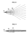
- Figs. 8 and 9 illustrate the configuration of a line generator according to Example 4 of the present invention.
- the line generator includes a laser diode light source 301, a first lens 303 which is a cylindrical lens and a second lens 305 which is a cylindrical lens.
- Fig. 8 shows a cross sectional view in the vertical direction (fast-axis (FA) direction) of the laser diode light source 301 while
- Fig. 9 shows a cross sectional view in the horizontal direction (slow-axis (SA) direction) of the laser diode light source 301.
- FA fast-axis
- SA slow-axis
- light emitted by the laser diode light source 301 is collimated by the first lens 303 in the SA direction to generate a light beam having a width of 3 millimeters.
- the width of the light beam after the collimation is that of the line generated by the line generator. Since the first lens 303 is a cylindrical one, the light is not collimated in the FA direction. The light collimated in the SA direction by the first lens 303 is diverged in the FA direction by the second lens 305 to generate the line.
- Table 11 shows data of the optical system of the line generator according to Example 4.
- Table 11 Surface No. Refractive index Abbe constant Surface interval Light source 3.0 2 First lens (Cylindrical surface) 1.80086 40.80 5.0 3 First lens (Free form surface) 3.0 4 Second lens (Cylindrical surface) 1.80086 40.80 2.0 5 Second lens (Cylindrical surface) 100
- the second surface (the surface on the object side of the first lens) is represented by the following expressions.
- Table 12 shows coefficients or constants in the expressions representing the second surface.
- Table 12 Second surface R -0.957 k 0
- the third surface (the surface on the image side of the first lens) is represented by the following expression.
- the third surface is a so-called free form surface.
- the free form surface is determined such that it is symmetric with respect to x-axis and y-axis, the lens power in the direction along y-axis is larger than that in the direction along x-axis and lens power in the direction along y-axis around the center differs from that at the periphery.
- Table 13 shows coefficients or constants in the expressions representing the third surface.
- Table 13 A02 -0.17820329 A22 0.0021122761 A04 -0.003687576 A42 -3.7905744x10 -5 A24 0.00018778603 A06 -0.0001530113 A62 9.073778x10 -7 A44 -1.2914223x10 -5 A26 2.627976x10 -5 A08 -1.1001855x10 -5
- the optical surfaces of the second lens are represented by the following expressions.
- Table 14 shows coefficients or constants in the expressions representing the fourth and fifth surfaces.
- Table 14 Fourth surface Fifth surface ⁇ 2 -0.17099751 -0.038119791 ⁇ 4 0.0 -0.00068518782
- the first lens 303 is used to determine a width of the line while the second lens 305 is used to generate the line which has a desired brightness distribution along it.
- function of the first lens 303 and that of the second lens 305 are clearly separated from each other.
- one of the laser diode light sources light emitting conditions of which varies from one to another is used as the laser diode light source 301, for example.
- brightness distribution along the line can be kept constant while the focal position is maintained by moving the second lens 305 along the optical axis.
- the focal position is adjusted by moving the first lens 303 in the optical direction, brightness distribution along the line remains unchanged.
- Figs. 25A and 25B illustrate an example of a mechanism used to move the first lens or the second lens along the optical axis.
- Fig. 25B shows a perspective view of the moving mechanism.
- the moving mechanism includes a lens barrel 2001 on the periphery of which a slit 2007 is provided in the longitudinal direction.
- Fig. 25A shows a cross sectional view of the moving mechanism.
- the cross section contains the central axis in the longitudinal direction.
- a lens holder 2003 is provided such that it can move along the central axis (that is, the optical axis).
- a handle 2005 is fixed to the lens holder 2003.
- the handle 2005 is configured such that it can be moved along the slit in the longitudinal direction. Accordingly, the lens holder 2003 can be moved along the optical axis by moving the handle 2005 along the slit 2007.
- Figs. 26A and 26B illustrate another example of a mechanism used to move the first lens or the second lens along the optical axis.
- Fig. 26A shows a cross sectional view of the moving mechanism.
- the cross section contains the central axis in the longitudinal direction.
- Fig. 26B shows another cross sectional view of the moving mechanism.
- the cross section is perpendicular to the central axis in the longitudinal direction.
- the moving mechanism includes a lens barrel 3001.
- An annular member 3005 is provided in a portion of the lens barrel 3001. The inside surface of the annular member 3005 is threaded.
- Inside the lens barrel 3001, a lens holder 3003 is provided inside the lens barrel 3001.
- the outside surface of the lens holder 3003 is threaded so as to be engaged with the threaded portion of the inside surface of the annular member 3005. Further, inside the lens barrel 3001, a stopper 3007 is provided such that the lens holder 3003 cannot rotate with respect to the lens barrel 3001. When the annular member 3005 is rotated with respect to the lens barrel 3001, the lens holder 3003 cannot rotate and therefore it moves in the longitudinal direction. Accordingly, the lens holder 3003 can be moved along the optical axis by rotating the annular member 3005.
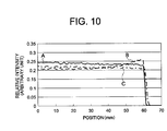
- Fig. 10 illustrates function to adjust an interval between the first and second lenses in the line generator according to Example 4.
- the horizontal axis of Fig. 10 represents distance between an arbitrary point on the line and the point of the intersection of the line and the optical axis.
- the vertical axis represents relative intensity of light at the arbitrary point.
- the illuminated surface is 100 mm away from the light source and perpendicular to the optical axis.
- Marked with A in Fig. 10 is intensity distribution of light along the line in the case that the diverging angle of the light source (laser diode) is 30 degrees (a designed value) and an interval between the first lens 303 and the second lens 305 is 3 millimeters. Intensity of light is substantially uniform along the line.
- Marked with B in Fig. 10 is intensity distribution of light along the line in the case that the diverging angle of the laser diode has been changed to 35 degrees. Intensity around the point of 60 millimeters is larger by 20 % or more than that around the optical axis.
- Marked with C in Fig. 10 is intensity distribution of light along the line in the case that the diverging angle of the laser diode is 35 degrees and an interval between the first lens 303 and the second lens 305 has been changed to 3 millimeters. By the adjustment of the interval between the lenses, intensity of light has become substantially uniform along the line.
- intensity of light can be maintained substantially uniform along the line by adjusting a position of the second lens 305 along the optical axis.
- Fig. 11 illustrates function to adjust an interval between the laser diode and the first lens in the line generator according to Example 4.
- the horizontal axis of Fig. 11 represents distance between an arbitrary point on the line and the point of the intersection of the line and the optical axis.
- the vertical axis represents relative intensity of light at the arbitrary point.
- Fig. 12 shows a layout of the line generator and the image plane.
- Marked with A in Fig. 11 is intensity distribution of light along the line in the case that an interval between the laser diode and the first lens is 4.0 millimeters. As shown in A of Fig. 12 , an interval between the second lens 305 and the image plane is 65 millimeters.
- Marked with B in Fig. 11 is intensity distribution of light along the line in the case that an interval between the laser diode and the first lens is 3.0 millimeters. As shown in B of Fig. 12 , an interval between the second lens 305 and the image plane is 100 millimeters.
- Marked with C in Fig. 11 is intensity distribution of light along the line in the case that an interval between the laser diode and the first lens is 2.5 millimeters. As shown in C of Fig. 12 , an interval between the second lens 305 and the image plane is 170 millimeters.
- intensity of light is substantially uniform along the line.
- intensity of light can be maintained substantially uniform along the line by adjusting the interval between the laser diode and the first lens.
- Figs. 13 and 14 illustrate the configuration of a line generator according to Example 5 of the present invention.
- the line generator includes a laser diode light source 401, a first lens 403 which is a cylindrical lens, a second lens 405 which is a cylindrical lens and a third lens 407 which is a cylindrical lens.
- Fig. 13 shows a cross sectional view in the vertical direction (fast-axis (FA) direction) of the laser diode light source 401 while
- Fig. 14 shows a cross sectional view in the horizontal direction (slow-axis (SA) direction) of the laser diode light source 401.
- FA fast-axis
- SA slow-axis
- light emitted by the laser diode light source 401 is collimated by the first lens 403 in the SA direction to generate a light beam having a width of 3 millimeters.
- the width of the light beam after the collimation is that of the line generated by the line generator. Since the first lens 403 is a cylindrical one, the light is not collimated in the FA direction.
- the light collimated in the SA direction by the first lens 403 is diverged in the FA direction by the second lens 405 and the third lens 407 to generate the line.
- Table 15 shows data of the optical system of the line generator according to Example 5.
- Table 15 Surface No. Refractive index Abbe constant Surface interval Light source 3.0 2 First lens (Cylindrical surface) 1.80086 40.80 5.0 3 First lens (Free form surface) 3.0 4 Second lens (Cylindrical surface) 1.80086 40.80 2.0 5 Second lens (Cylindrical surface) 2.0 6 Third surface (Cylindrical surface) 1.80086 40.80 2.0 7 Third surface (Plane)
- the second surface (the surface on the object side of the first lens) is represented by the following expressions.
- Table 16 shows coefficients or constants in the expressions representing the second surface.
- Table 16 Second surface R -0.957 k 0
- the third surface (the surface on the image side of the first lens) is represented by the following expression.
- the third surface is a so-called free form surface.
- the free form surface is determined such that it is symmetric with respect to x-axis and y-axis, the lens power in the direction along y-axis is larger than that in the direction along x-axis and lens power in the direction along y-axis around the center differs from that at the periphery.
- Table 17 shows coefficients or constants in the expressions representing the third surface.
- Table 17 A02 -0.17820329 A22 0.0021122761 A04 -0.003687576 A42 -3.7905744x10 -5 A24 0.00018778603 A06 -0.0001530113 A62 9.073778x10 -7 A44 -1.2914223x10 -5 A26 2.627976x10 -5 A08 -1.1001855x10 -5
- the optical surfaces of the second lens are represented by the following expression.
- Table 18 shows coefficients or constants in the expressions representing the fourth and fifth surfaces.
- Table 18 Fourth surface Fifth surface ⁇ 2 -0.105563 -0.045224 ⁇ 4 0.0 -1.968589x10 -3
- the optical surfaces of the third lens are represented by the following expressions.
- ⁇ 2 i represents correcting coefficients.
- Table 19 shows coefficients or constants in the expressions representing the sixth and seventh surfaces.
- Table 19 Sixth surface Seventh surface R -12.149557 infinity k 0 0
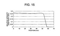
- Fig. 15 illustrates performance of the line generator according to Example 5.
- the horizontal axis of Fig. 15 represents distance between an arbitrary point on the line and the point of the intersection of the line and the optical axis.
- the vertical axis represents relative intensity of light at the arbitrary point.
- the illuminated surface is 100 mm away from the light source and perpendicular to the optical axis. Brightness along the line is substantially uniform.
- two lenses (the second lens 405 and the third lens 407) share function to diverge light in the FA direction.
- the second lens 405 and the third lens 407 form the second lens group.
- individual lenses in the second lens group can be designed and produced more easily.
- Figs. 16 and 17 illustrate the configuration of a line generator according to Example 6 of the present invention.
- the line generator includes a laser diode light source 501, a first lens 503 which is a cylindrical lens and a second lens 505 which has a free from surface as the image side surface (the fifth surface).
- Fig. 16 shows a cross sectional view in the vertical direction (fast-axis (FA) direction) of the laser diode light source 501
- Fig. 17 shows a cross sectional view in the horizontal direction (slow-axis (SA) direction) of the laser diode light source 501.
- FA fast-axis
- SA slow-axis
- light emitted by the laser diode light source 501 is collimated by the first lens 503 in the SA direction. Since the first lens 503 is a cylindrical one, the light is not collimated in the FA direction.
- the light collimated in the SA direction by the first lens 503 is diverged in the FA direction and focused in the SA direction by the
- Table 20 shows data of the optical system of the line generator according to Example 6.
- Table 20 Surface No. Refractive index Abbe constant Surface interval Light source 3.0 2 First lens (Plane) 1.80086 40.80 2.0 3 First lens (Cylindrical surface) 4.0 4 Second lens (Cylindrical surface) 1.80086 40.80 1.5 5 Second lens (Free surface) 65
- the second surface (the object side surface of the first lens) and the third surface (the image side surface of the first lens) are represented by the following expressions.
- the fourth surface (the object side surface of the second lens) is represented by the following expressions.
- Table 21 shows coefficients or constants in the expressions representing the second to fourth surfaces.
- Table 21 Second surface Third surface Fourth surface R infinity -3.3882 -15
- the fifth surface (the image side surface of the second lens) is represented by the following expressions.
- the fifth surface is a so-called free form surface.
- Table 22 shows coefficients or constants in the expressions representing the fifth surface.
- Table 22 A02 -1.451264E-02 A22 1.326452E-03 A04 1.798895E-03 A42 -5.888678E-06 A24 2.604972E-05 A06 8.171482E-05 A62 9.123176E-08 A44 2.833025E-06 A26 3.150682E-05 A08 7.367080E-05
- optimal focusing performance of a line generator which generates a line whose intensity distribution of light is not uniform along the line can be obtained as below. That is, to obtain optimal focusing performance, focusing property of the second lens is changed using the free form surface based on intensity distribution of light along the line while the specification of the first lens (group) is not changed.
- Figs. 18 and 19 illustrate the configuration of a line generator according to Example 7 of the present invention.
- the line generator includes a laser diode light source 601, a first lens 603 which is a cylindrical lens and a second lens 605 which is a cylindrical lens.
- the line generator according to the present example further includes a phase plate 607 which has a free form surface on the object side (the fourth surface) between the first lens 603 and the second lens 605.
- Fig. 18 shows a cross sectional view in the vertical direction (fast-axis (FA) direction) of the laser diode light source 601 while
- Fig. 19 shows a cross sectional view in the horizontal direction (slow-axis (SA) direction) of the laser diode light source 601.
- FA fast-axis
- SA slow-axis
- light emitted by the laser diode 601 is collimated by the first lens 603 in the SA direction. Since the first lens 603 is a cylindrical one, the light is not collimated in the FA direction.
- the light collimated in the SA direction by the first lens 603 is adjusted by the phase plate 607, diverged in the FA direction and focused in the SA direction by the second lens 605 to generate the line.
- Table 23 shows data of the optical system of the line generator according to Example 7.
- Table 23 Surface No. Refractive index Abbe constant Surface interval Light source 3.0 2 First lens (Plane) 1.80086 40.80 2.0 3 First lens (Cylindrical surface) 1.0 4 Phase plate (Free form surface) 1.51680 64.167 1.0 5 Phase plate (Plane) 2.0 6 Second lens (Cylindrical surface) 1.80086 40.80 1.5 7 Second lens (Plane) 65
- the second surface (the object side surface of the first lens) and the third surface (the image side surface of the first lens) are represented by the following expressions.
- the sixth surface (the object side surface of the second lens) and the seventh surface (the image side surface of the second lens) are represented by the following expressions.
- Table 24 shows coefficients or constants in the expressions representing the second, third, sixth and seventh surfaces.
- Table 24 Second surface Third surface Sixth surface Seventh surface R Second infinity -3.3882 -15 infinity
- the fourth surface (the image side surface of the phase plate) is represented by the following expressions.
- the fourth surface is a so-called free form surface.
- Table 25 shows coefficients or constants in the expressions representing the fourth surface.
- Table 25 A02 2.187796E-02 A22 -6.785688E-03 A04 -3.012261E-03 A42 1.595686E-04 A24 7.412937E-05 A06 -1.617339E-04 A62 -3.065133E-06 A44 -2.045186E-05 A26 -3.206443E-05 A08 -3.290733E-05
- an optical element including a free form surface that is difficult to produce can be produced independently of lenses and therefore the producing process is simplified.
- Figs. 20 and 21 illustrate the configuration of a line generator according to Example 8 of the present invention.
- the line generator includes a laser diode light source 701, a first lens 703 which has a free form surface on the image side (the third surface), a second lens 705 which is a cylindrical lens and a third lens 707 which is a cylindrical lens.
- Fig. 20 shows a cross sectional view in the vertical direction (fast-axis (FA) direction) of the laser diode light source 701 while
- Fig. 21 shows a cross sectional view in the horizontal direction (slow-axis (SA) direction) of the laser diode light source 701.
- FA fast-axis
- SA slow-axis
- light emitted by the laser diode 701 is collimated in the SA direction by the first lens 703 and the second lens 705.
- the first lens 703 and the second lens 705 form a first lens group.
- the light collimated in the SA direction by the first lens group is diverged in the FA direction by the third lens 707 to generate the line.
- Table 26 shows data of the optical system of the line generator according to Example 8.
- Table 26 Surface No. Refractive index Abbe constant Surface interval Light source 2.5 2 First lens (Cylindrical surface) 1.80086 40.8 1.0 3 First lens (Free form surface) 1.0 4 Second lens (Plane) 1.80086 40.8 2.0 5 Second lens (Cylindrical surface) 2.5 6 Third lens (Cylindrical surface) 1.5176 63.5 1.0 7 Third lens (Cylindrical surface) 5000
- the second surface (the object side surface of the first lens), the fourth surface (the object side surface of the second lens) and the fifth surface (the image side surface of the second lens) are represented by the following expressions.
- Table 27 shows coefficients or constants in the expressions representing the second, fourth and fifth surfaces.
- Table 27 Second surface Fourth surface Fifth surface R -2 infinity -3.348
- the third surface (the image side surface of the first lens) is represented by the following expression.
- the third surface is a so-called free form surface.
- Table 28 shows coefficients or constants in the expressions representing the third surface.
- Table 28 A02 -0.04702 A22 0.0344 A04 0.027209 A42 -0.00038 A24 0.009589 A06 0.004538 A62 0.000134 A44 6.15E-05 A26 0.001836 A08 0.000433 A82 -2.64E-06 A64 0.000423 A46 0.001679 A28 0.002551 A010 0.000792
- the sixth surface (the object side surface of the third lens) and the seventh surface (the image side surface of the third lens) are represented by the following expression.
- Table 29 shows coefficients or constants in the expressions representing the sixth and seventh surfaces. Table 29 Sixth surface Seventh surface A4 -4.00E-03 0 A6 -1.00E-03 0
- Fig. 22 illustrates intensity of light along the line on the plane located at a position 5 meters away from the light source plane when illuminated by the line generator according to Example 8.
- the horizontal axis of the graph in Fig. 22 represents distance from an illuminated spot to the intersection point of the illuminated surface and the line connecting the light source and the illuminated surface and perpendicular to the illuminated surface.
- the vertical axis represents intensity of light in arbitrary unit.
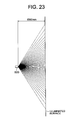
- Fig. 23 illustrates a positional relationship between the line generator 500 according to Example 8 and the illuminated surface.
- focusing performance can be improved by adjusting a shape of the first lens 703 in the first lens group while intensity of light along the line can be controlled by the second lens group (the third lens 707).
- intensity of light is made larger at the center (the intersection point described above) and intensity of light is made to gradually decrease depending on distance from the center to obtain a certain length of line.
- Fig. 24 illustrates a positional relationship between the line generator and the illuminated surface in general.
- point A indicates the intersection point of the illuminated surface and the line connecting the light source and the illuminated surface and perpendicular to the illuminated surface.
- Point B indicates a point on the line away form the point A.
- An optical path length from the light source to the point A is smaller than that form the light source to the point B.
- an optical path length from the light source to a point on the line on the illuminated surface will vary depending on diverging angle of light from the light source. Accordingly, it is difficult to collimate or to focus light for the whole length of the line with high accuracy. Under the situation described above, when a free form surface is used to adjust the focal position, light can be focused with higher accuracy at any point on the line on the illuminated surface which is a plane or a curved surface.
- laser diodes are used as the light source.
- Light emitting diodes or light transmitted through optical fibers are also used as the light source.
Landscapes
- Physics & Mathematics (AREA)
- General Physics & Mathematics (AREA)
- Optics & Photonics (AREA)
- Engineering & Computer Science (AREA)
- Radar, Positioning & Navigation (AREA)
- Remote Sensing (AREA)
- Lenses (AREA)
- Semiconductor Lasers (AREA)
Applications Claiming Priority (2)
| Application Number | Priority Date | Filing Date | Title |
|---|---|---|---|
| US18182209P | 2009-05-28 | 2009-05-28 | |
| PCT/JP2009/004563 WO2010137082A1 (ja) | 2009-05-28 | 2009-09-14 | ラインジェネレータ |
Publications (1)
| Publication Number | Publication Date |
|---|---|
| EP2256458A1 true EP2256458A1 (de) | 2010-12-01 |
Family
ID=43222228
Family Applications (1)
| Application Number | Title | Priority Date | Filing Date |
|---|---|---|---|
| EP10163168A Ceased EP2256458A1 (de) | 2009-05-28 | 2010-05-18 | Linienerzeuger |
Country Status (5)
| Country | Link |
|---|---|
| US (1) | US8085468B2 (de) |
| EP (1) | EP2256458A1 (de) |
| JP (1) | JPWO2010137082A1 (de) |
| CN (1) | CN101900843A (de) |
| WO (1) | WO2010137082A1 (de) |
Cited By (2)
| Publication number | Priority date | Publication date | Assignee | Title |
|---|---|---|---|---|
| US8974086B2 (en) | 2011-03-09 | 2015-03-10 | Nalux Co., Ltd. | Lens, mold for lens and method for machining mold |
| EP3581844A4 (de) * | 2017-02-13 | 2020-09-09 | Omron Corporation | Laserbeleuchtungsvorrichtung und damit ausgestatteter peripherer überwachungssensor |
Families Citing this family (6)
| Publication number | Priority date | Publication date | Assignee | Title |
|---|---|---|---|---|
| US9400391B2 (en) * | 2012-09-27 | 2016-07-26 | Coherent, Inc. | Uniformity adjustment method for a diode-laser line-projector |
| DE102013114083B4 (de) * | 2013-12-16 | 2018-10-25 | LIMO GmbH | Vorrichtung zur Formung von Laserstrahlung |
| EP3154520B1 (de) * | 2014-06-13 | 2020-04-29 | HEIDELTEC GmbH | Matrixstabilisierte liposomen |
| CN106940467A (zh) * | 2016-01-05 | 2017-07-11 | 北京雷动云合智能技术有限公司 | 一种用于激光测距装置的超广角条状视场镜头 |
| CN106249422A (zh) * | 2016-09-28 | 2016-12-21 | 北京万集科技股份有限公司 | 多路光束处理光学系统及其处理方法、多路激光探测器 |
| US11396994B1 (en) * | 2021-02-16 | 2022-07-26 | Ii-Vi Delaware, Inc. | Laser light source having diffuser element and light diverging optic |
Citations (6)
| Publication number | Priority date | Publication date | Assignee | Title |
|---|---|---|---|---|
| US5095386A (en) * | 1990-05-01 | 1992-03-10 | Charles Lescrenier | Optical system for generating lines of light using crossed cylindrical lenses |
| US5721416A (en) * | 1995-06-01 | 1998-02-24 | Microlas Lasersystem Gmbh | Optics for forming a sharp illuminating line of a laser beam |
| US6069748A (en) | 1998-10-20 | 2000-05-30 | Eastman Kodak Company | Laser line generator system |
| US20060176912A1 (en) * | 2005-02-07 | 2006-08-10 | Anikitchev Serguei G | Apparatus for projecting a line of light from a diode-laser array |
| WO2007048506A1 (en) * | 2005-10-28 | 2007-05-03 | Carl Zeiss Laser Optics Gmbh | Optical device for generating a line focus on a surface |
| JP2008058295A (ja) | 2006-08-02 | 2008-03-13 | Ayase:Kk | レーザラインジェネレータ、レーザモジュール及びレーザ墨出し装置 |
Family Cites Families (3)
| Publication number | Priority date | Publication date | Assignee | Title |
|---|---|---|---|---|
| JP2002221416A (ja) * | 2001-01-25 | 2002-08-09 | Naokuni Sato | 墨出し装置 |
| JP2007232696A (ja) * | 2006-03-03 | 2007-09-13 | Sts Kk | 墨出用のレーザー照射装置 |
| JP4332190B2 (ja) * | 2007-09-28 | 2009-09-16 | 株式会社 彩世 | レーザラインジェネレータ及びレーザラインジェネレータモジュール |
-
2009
- 2009-09-14 WO PCT/JP2009/004563 patent/WO2010137082A1/ja not_active Ceased
- 2009-09-14 JP JP2009550133A patent/JPWO2010137082A1/ja active Pending
-
2010
- 2010-05-18 EP EP10163168A patent/EP2256458A1/de not_active Ceased
- 2010-05-27 CN CN201010193390.0A patent/CN101900843A/zh active Pending
- 2010-07-06 US US12/830,545 patent/US8085468B2/en active Active
Patent Citations (6)
| Publication number | Priority date | Publication date | Assignee | Title |
|---|---|---|---|---|
| US5095386A (en) * | 1990-05-01 | 1992-03-10 | Charles Lescrenier | Optical system for generating lines of light using crossed cylindrical lenses |
| US5721416A (en) * | 1995-06-01 | 1998-02-24 | Microlas Lasersystem Gmbh | Optics for forming a sharp illuminating line of a laser beam |
| US6069748A (en) | 1998-10-20 | 2000-05-30 | Eastman Kodak Company | Laser line generator system |
| US20060176912A1 (en) * | 2005-02-07 | 2006-08-10 | Anikitchev Serguei G | Apparatus for projecting a line of light from a diode-laser array |
| WO2007048506A1 (en) * | 2005-10-28 | 2007-05-03 | Carl Zeiss Laser Optics Gmbh | Optical device for generating a line focus on a surface |
| JP2008058295A (ja) | 2006-08-02 | 2008-03-13 | Ayase:Kk | レーザラインジェネレータ、レーザモジュール及びレーザ墨出し装置 |
Cited By (3)
| Publication number | Priority date | Publication date | Assignee | Title |
|---|---|---|---|---|
| US8974086B2 (en) | 2011-03-09 | 2015-03-10 | Nalux Co., Ltd. | Lens, mold for lens and method for machining mold |
| EP3581844A4 (de) * | 2017-02-13 | 2020-09-09 | Omron Corporation | Laserbeleuchtungsvorrichtung und damit ausgestatteter peripherer überwachungssensor |
| US11269062B2 (en) | 2017-02-13 | 2022-03-08 | Omron Corporation | Laser illumination device and peripheral monitoring sensor provided with same |
Also Published As
| Publication number | Publication date |
|---|---|
| CN101900843A (zh) | 2010-12-01 |
| JPWO2010137082A1 (ja) | 2012-11-12 |
| US8085468B2 (en) | 2011-12-27 |
| US20110002042A1 (en) | 2011-01-06 |
| WO2010137082A1 (ja) | 2010-12-02 |
Similar Documents
| Publication | Publication Date | Title |
|---|---|---|
| EP2256458A1 (de) | Linienerzeuger | |
| US20220187611A1 (en) | Optical element arrangements for varying beam parameter product in laser delivery systems | |
| US6443594B1 (en) | One-piece lens arrays for collimating and focusing light and led light generators using same | |
| US6195208B1 (en) | Single aspherical lens for de-astigmatism, collimation, and circulation of laser beams | |
| US6407870B1 (en) | Optical beam shaper and method for spatial redistribution of inhomogeneous beam | |
| US9784934B2 (en) | Laser device | |
| EP3435141B1 (de) | Parallele lichterzeugungsvorrichtung | |
| US11435591B2 (en) | Apparatus for collimating a light ray field | |
| US20130293965A1 (en) | Free-space combining of laser beam radiation | |
| US20230117164A1 (en) | Diffuser device | |
| CN109791303A (zh) | 利用可变光束形状的激光的材料加工 | |
| KR20150096760A (ko) | 경사면들에서의 스팟 어레이의 발생 | |
| CN1997928A (zh) | 用于使光均匀化的装置和用这种装置进行照明或聚焦的结构 | |
| US7580601B2 (en) | Anamorphic aspherical beam focusing lens | |
| US20190173255A1 (en) | Laser Diode Device and a Projector Using Same | |
| JP2019020731A (ja) | レーザビームの線形強度分布を生成するための装置 | |
| US7495837B2 (en) | Collimating lens structures | |
| JP2005157358A (ja) | 特に高出力ダイオード・レーザに対するビーム整形のための屈折性・回折性ハイブリッド型レンズ | |
| TWI743493B (zh) | 光學組件和雷射系統 | |
| JP4599514B2 (ja) | ラインジェネレータ | |
| JP5546410B2 (ja) | 光学部材、これを用いた光通信モジュール及び調芯方法 | |
| US8974086B2 (en) | Lens, mold for lens and method for machining mold | |
| EP4524643A1 (de) | Vorrichtung zur erzeugung schmaler strahlen | |
| EP3730994B1 (de) | Parallele lichterzeugungsvorrichtung | |
| JP2017173717A (ja) | プロジェクタ |
Legal Events
| Date | Code | Title | Description |
|---|---|---|---|
| PUAI | Public reference made under article 153(3) epc to a published international application that has entered the european phase |
Free format text: ORIGINAL CODE: 0009012 |
|
| 17P | Request for examination filed |
Effective date: 20101013 |
|
| AK | Designated contracting states |
Kind code of ref document: A1 Designated state(s): AL AT BE BG CH CY CZ DE DK EE ES FI FR GB GR HR HU IE IS IT LI LT LU LV MC MK MT NL NO PL PT RO SE SI SK SM TR |
|
| AX | Request for extension of the european patent |
Extension state: BA ME RS |
|
| 17Q | First examination report despatched |
Effective date: 20110331 |
|
| STAA | Information on the status of an ep patent application or granted ep patent |
Free format text: STATUS: THE APPLICATION HAS BEEN REFUSED |
|
| 18R | Application refused |
Effective date: 20120301 |