EP2256751B1 - Bobine électromagnétique avec dispositifs de connection - Google Patents
Bobine électromagnétique avec dispositifs de connection Download PDFInfo
- Publication number
- EP2256751B1 EP2256751B1 EP10163596.9A EP10163596A EP2256751B1 EP 2256751 B1 EP2256751 B1 EP 2256751B1 EP 10163596 A EP10163596 A EP 10163596A EP 2256751 B1 EP2256751 B1 EP 2256751B1
- Authority
- EP
- European Patent Office
- Prior art keywords
- head portions
- pins
- electromagnetic coil
- coil means
- pin
- Prior art date
- Legal status (The legal status is an assumption and is not a legal conclusion. Google has not performed a legal analysis and makes no representation as to the accuracy of the status listed.)
- Active
Links
Images


Classifications
-
- H—ELECTRICITY
- H01—ELECTRIC ELEMENTS
- H01F—MAGNETS; INDUCTANCES; TRANSFORMERS; SELECTION OF MATERIALS FOR THEIR MAGNETIC PROPERTIES
- H01F5/00—Coils
- H01F5/04—Arrangements of electric connections to coils, e.g. leads
-
- H—ELECTRICITY
- H01—ELECTRIC ELEMENTS
- H01F—MAGNETS; INDUCTANCES; TRANSFORMERS; SELECTION OF MATERIALS FOR THEIR MAGNETIC PROPERTIES
- H01F7/00—Magnets
- H01F7/06—Electromagnets; Actuators including electromagnets
-
- H—ELECTRICITY
- H02—GENERATION; CONVERSION OR DISTRIBUTION OF ELECTRIC POWER
- H02K—DYNAMO-ELECTRIC MACHINES
- H02K3/00—Details of windings
- H02K3/46—Fastening of windings on the stator or rotor structure
- H02K3/52—Fastening salient pole windings or connections thereto
- H02K3/521—Fastening salient pole windings or connections thereto applicable to stators only
- H02K3/525—Annular coils, e.g. for cores of the claw-pole type
-
- H—ELECTRICITY
- H02—GENERATION; CONVERSION OR DISTRIBUTION OF ELECTRIC POWER
- H02K—DYNAMO-ELECTRIC MACHINES
- H02K5/00—Casings; Enclosures; Supports
- H02K5/04—Casings or enclosures characterised by the shape, form or construction thereof
- H02K5/22—Auxiliary parts of casings not covered by groups H02K5/06-H02K5/20, e.g. shaped to form connection boxes or terminal boxes
- H02K5/225—Terminal boxes or connection arrangements
-
- H—ELECTRICITY
- H01—ELECTRIC ELEMENTS
- H01F—MAGNETS; INDUCTANCES; TRANSFORMERS; SELECTION OF MATERIALS FOR THEIR MAGNETIC PROPERTIES
- H01F7/00—Magnets
- H01F7/06—Electromagnets; Actuators including electromagnets
- H01F2007/062—Details of terminals or connectors for electromagnets
-
- H—ELECTRICITY
- H01—ELECTRIC ELEMENTS
- H01F—MAGNETS; INDUCTANCES; TRANSFORMERS; SELECTION OF MATERIALS FOR THEIR MAGNETIC PROPERTIES
- H01F7/00—Magnets
- H01F7/06—Electromagnets; Actuators including electromagnets
- H01F7/08—Electromagnets; Actuators including electromagnets with armatures
- H01F7/16—Rectilinearly-movable armatures
- H01F2007/1692—Electromagnets or actuators with two coils
Definitions
- the present invention relates to the field of mechanical electronics; more particularly, to an electromagnetic coil means.
- Electromagnetic coil means may be applied in various fields. For example, it may be used as the coil of electronic expansion valve in an air-conditioner refrigeration system, which is a typical use thereof, or used as the stator part in a step motor, or used in an electronic device having a plurality of terminals connected with lead by means of soldering.
- US 5,057,732 describes an electric motor comprising a stator disposed in a housing and including a coil bobbing, an exciting coil wound on said coil bobbing and at least two connector plates fixed to said coil bobbing. Further, the electric motor comprises a rotor rotatably supported in the housing and positioned concentrically to the stator.
- JP 2008/253104 A describes a motor equipped with driving coils assembled in a stator and a terminal block at which a plurality of terminal pins are installed.
- the terminal pins are connected with the driving coils and are each composed of a mounting part mounted on the terminal block and a binding part connected with the driving coils.
- the mounting parts are installed so as to protrude in the radial direction of the motor while the binding parts are folded in the direction different from the radial direction of the motor.
- Fig.1 is a schematic view showing the structure of a typical electromagnetic coil means in the prior art.
- the electromagnetic coil means in the prior art includes a terminal part 12 and some pins 11 passing through the terminal part 12.
- the pins 11 are divided into a first group of pins connected with an upper coil stator and a second group of pins connected with a lower coil stator, in which the first and the second groups of pins are disposed spaced from each other.
- a head portion of the pin 11 passes through a pin leading-out surface 121 of the terminal part 12.
- the electromagnetic coil means has a frame including an upper frame 13 and a lower frame 14, which have an integral structure.
- the pins 11 of the electromagnetic coil means are connected with cable leads 15 by means of a circuit board 16.
- the circuit board 16 has pin holes 162 and core holes 161 each as many as the pins 11, and the pin holes 162 and the core holes 161 are arranged in pairs.
- the pin head portion 111 extends out from the pin hole 162, and a head portion 151 of the cable lead extends out from the core hole 161.
- the pin head portion 111 is soldered to the cable lead head portion 151 through soldering materials.
- the technical problem to be solved by the present invention is to provide an electromagnetic coil means which has a structure designed to be capable of improving the insulation performance between solder joints of pin head portions, and facilitating the soldering operation, thus to ensure the stability and reliability of the operation of the electromagnetic coil means.
- the present invention pro-vides an electromagnetic coil means according to claim 1.
- the pin leading-out surface is an inclined surface, and an appropriate acute angle is formed between the centerlines of the first and second head portions and the inclined surface.
- the pin leading-out surface comprises an upper step surface and a lower step surface substantially parallel to the upper step surface; the first head portions are substantially perpendicular to the upper step surface, and the second head portions are substantially perpendicular to the lower step surface.
- each of said pins has the same length, and every adjacent first inner section and second inner section have equal distance these between and lie in the same horizontal plane; the horizontal distance between the plane in which the centerlines of the first outer sections lies and the plane in which the centerlines of the second outer sections lies is less than 4 ⁇ 3 2 times the distance between adjacent first inner section and second inner section.
- the horizontal distance equals to 3 2 times the distance between adjacent first inner section and second inner section.
- the pin leading-out surface is an inclined surface; first middle portions between the first inner sections and the first head portions are substantially perpendicular to the first inner sections, and an appropriate angle is formed between the centerlines of the first head portions and that of the first middle portions; second middle portions between the second inner sections and the second head portions are substantially perpendicular to the second inner sections, and an appropriate angle is formed between the centerlines of the second head portions and that of the second middle portions; the first and second head portions are substantially perpendicular to the inclined surface.
- the electromagnetic coil means comprises cable leads and a circuit board, the first and second head portions being connected with the cable leads by means of the circuit board; and the terminal part has linear grooves for receiving the cable leads.
- the circuit board comprises pin holes and core holes each as many as the pins; the pin holes and core holes are arranged in pairs adjacent to each other and connected with each other by conducting materials; the first and second head portions extend out from the pin holes, and head portions of the cable leads extend out from the core holes; the first and second head portions are soldered with the head portions of the cable leads by soldering materials.
- the center distance between the pin holes and the core holes is greater than 0.5 times the sum of the diameter of the pin holes and the diametre of the core holes and less than 5 times thereof.
- the electromagnetic coil means may comprise a cover with a protruded locating portion, and the terminal part may comprise a locating groove engaging with the protruded locating portion; and the protruded locating portion may engage with the locating groove and may be sealed therewith by resin materials.
- the electromagnetic coil means may comprise a frame, which in turn comprises an upper frame and a lower frame detachable from the upper frame, and the upper and lower frames may have the same structure and size.
- both the first and second groups of pins are bent upward, and a distance between adjacent said first and second head portions is larger than that between adjacent said first and second root portions.
- the increase of the distance between adjacent first and second head portions enables to increase the distance between solder joints of adjacent pin head portions without increasing the overall volume of the electromagnetic coil means, thus the insulation performance between solder joints of adjacent pin head portions is improved and soldering operation is facilitated, ensuring the stability and reliability of the operation of the electromagnetic coil means.
- Fig.1 is a schematic view of the structure of a typical electromagnetic coil means in the prior art
- Fig.2 is an assembly flowchart of an electromagnetic coil means provided in a first embodiment of the present invention
- Fig.3 is a schematic view of the structure of an electromagnetic coil means provided in a second embodiment of the present invention.
- Fig.4 is a schematic view of the relative position of a first and a second groups of pins in the electromagnetic coil means provided in the second embodiment of the present invention
- Fig.5 is a top view of the relative position of the first and second groups of pins in the electromagnetic coil means provided in the second embodiment of the present invention.
- Fig.6 is a schematic view of the structure of an electromagnetic coil means provided in a third embodiment of the present invention.
- Fig.7 is schematic section view of the electromagnetic coil means provided in the third embodiment of the present invention.
- Fig.8 is a schematic view of the structure of an electromagnetic coil means not forming part of the present invention.
- Fig.9 is a schematic view of installation of a cover of electromagnetic coil means provided in the second embodiment of the present invention.
- Fig.10 a schematic view of installation of a cover of electromagnetic coil means shown in Fig. 8 .
- the present invention is intended to provide an electromagnetic coil means which is designed with a structure that improves the insulation performance between solder joints of pin head portions and facilitates the soldering operation, ensuring the stability and reliability of the operation of the electromagnetic coil means.
- Fig.2 is an assembly flowchart of an electromagnetic coil means provided in a first embodiment of the present invention.
- Enameled wire is wound onto an upper frame 271, and the ends of the enameled wire are connected with first root portions 212b of a first group of pins 21, forming an upper coil stator on which an upper electromagnetic polar board 281 is mounted.
- Enameled wire is wound onto a lower frame 272, and the ends of the enameled wire are connected with second root portions 222b of a second group of pins 22, forming a lower coil stator on which a lower electromagnetic polar board 282 is mounted.
- the upper coil stator mounted with the upper electromagnetic polar board 281 and the lower coil stator mounted with the lower electromagnetic polar board 281 are assembled together, forming an electromagnetic coil stator.
- the electromagnetic coil stator is assembled with an upper shell 292 and a lower shell 291, forming a stator component.
- stator component with bent pins is positioned into a plastic resin packaging model so as to be packaged by injection molding, forming a terminal part 23 of the electromagnetic coil means. Consequently, the assembly of the electromagnetic coil means is completed.
- a plurality of different embodiments of the electromagnetic coil means provided in the present invention are obtained depending on different bending ways of the pins of the stator component.
- the assembly process of the electromagnetic coil means provided in each of the following plurality of different embodiments of this invention is the same as that provided in the first embodiment, and the detailed description thereof will be omitted.
- both the first and second groups of pins 21, 22 are bent upward, in which first outer sections 211 are substantially perpendicular to first inner sections 212, and second outer sections 221 are substantially perpendicular to second inner sections 222.
- a plane in which the centerlines of the first outer sections 211 lie and a plane in which the centerlines of the second outer sections 221 lie are substantially parallel to each other and are of an appropriate distance horizontally.
- the first and second head portions 211a, 221a extend out from the pin leading-out surface of the terminal part 23 which is an inclined surface 231, and an appropriate acute angle is formed between the first and second head portions 211a, 221a and the inclined surface 231.
- the first and second groups of pins 21, 22 described in last paragraph are bent upward relative to the electromagnetic coil means disposed as shown in Fig.2 .
- the pin may be bent in the following way (and procedures before the bending of pins may be made a reference to the preceding description of Fig.2 ): the stator component is placed into a bending machine tool; by setting a distance on the machine tool, the pins are divided into a first group of pins 21 and a second group of pins 22 spaced by an appropriate distance; then, the pins are bent by downward pressure provided by a cylinder or other facilities; the angle of bending is 90°, and of course, could be any other appropriate angles. It is also possible to perform the bending procedure earlier, right after the enameled wires of the upper and lower coil stators are wounded, in this case, the bending way of the pins of the upper and lower coil stators are the same.
- first head portions 211a and the second head portions 221a there is a height difference between the first head portions 211a and the second head portions 221a in a vertical direction, and the pin leading-out surface is provided as an inclined surface 231 which has an appropriate acute angle with respect to the first head portions 211a and second head portions 221a.
- the first head portions 211a and the second head portions 221a protrude from the inclined surface 231, respectively, by lengths which are long enough and substantially equal, facilitating the soldering operation.
- Fig.3 is a schematic view of the structure of an electromagnetic coil means provided in a second embodiment of the present invention.
- the second embodiment of the present invention is a variation of the first embodiment in which the shape of the terminal part 23 is varied.
- the bending direction of the pins in the second embodiment is the same as that in the first embodiment, thus a detailed description thereof is omitted.
- the pin leading-out surface of the terminal part 23 includes an upper step surface 232 and a lower step surface 233 that is substantially parallel to the upper step surface 232.
- the first head portions 211a are substantially perpendicular to the upper step surface 232 and the second head portions 221a are substantially perpendicular to the lower step surface 233.
- the bending method of pins in the second embodiment is the same as that in the first embodiment, thus a detailed description thereof is omitted.
- the first and second head portions 211a, 221a are substantially perpendicular to the upper and lower step surfaces 232, 233, respectively, the first and second head portions 211a, 221a are enabled to protrude from the upper and lower step surfaces 232, 233 by lengths long enough, respectively, thus the operation of soldering is facilitated.
- the pin leading-out surface is provided as upper and lower step surfaces 232, 233 which have a height difference in the vertical direction.
- Fig.4 is a schematic view of the relative position of a first and a second groups of pins in the electromagnetic coil means provided in the second embodiment of the present invention
- Fig.5 is a top view of the relative position of the first and second groups of pins in the electromagnetic coil means provided in the second embodiment of the present invention.
- each of the pins has equal size, and adjacent first and second inner sections 212, 222 have equal distance therebetween and are disposed in the same horizontal plane.
- the distance between adjacent first and second inner sections 212, 222 are indicated with T, and the distance between adjacent first inner sections 212 and the distance between adjacent second inner sections 222 are indicated with 2T.
- the horizontal distance between the planes in which the centerlines of the first and second outer sections 211, 221 are disposed is indicated with L.
- the distances between adjacent ends of adjacent first head portion 211a, the second head portion 221a, and next first head portion 211a or the distances between adjacent ends of adjacent second head portion 221a, first head portion 211a, and next second head portion 221a are substantially equal, and a generally regular triangle is formed by the ends of the three adjacent head portions.
- the insulation distances between adjacent solder joints of those three adjacent pin head portions are substantially equal, thus a favorable comprehensive insulation performance between the solder joints of pin head portions is provided.
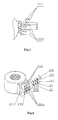
- Fig.6 is a schematic view of the structure of an electromagnetic coil means provided in a third embodiment of the present invention
- Fig.7 is schematic section view of the electromagnetic coil means provided in the third embodiment of the present invention.
- the pin leading-out surface is an inclined surface 234, and first and second groups of pins 21, 22 (both shown in Fig.2 ) bend upward.
- Middle portions 211b between the first inner sections 212 (shown in Fig.2 ) and the first head portion 211a are substantially perpendicular to the first inner sections 212, and an appropriate angle is formed between the first head portions 211a and the first middle portions 211b.
- Middle portions 221b between the second inner sections 222 and the second head portions 221a are substantially perpendicular to the second inner sections 222, and an appropriate angle is formed between the second head portions 221a and the second middle portions 221b.
- the first and second head portions 211a, 221a are substantially perpendicular to the inclined surface 234.
- the bending method in the third embodiment is the same as that in the first embodiment.
- the packaged stator component needs to be placed onto a machine tool.
- the first and second head portions 211a, 221a are bent under a downward pressure provided by a cylinder or other facilities bend by an appropriate angle, such that they are substantially perpendicular to the inclined surface 234.
- the first and second head portions 211a, 221a in the third embodiment are arranged to be generally perpendicular to the inclined surface 234. This arrangement facilitates the extending of first and second head portions 211a, 221a out from the inclined surface 234, thus the soldering operation is further facilitated while favorable insulation performance between solder joints of adjacent pin head portions is ensured.
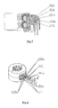
- Fig.8 is a schematic view of the structure of an electromagnetic coil means not forming part of the present invention.
- One group of the first and second groups of pins 21, 22 bends upward, while the other group bends downward.
- a plane in which the centerlines of the first outer sections 211 lie and a plane in which the centerlines of the second outer sections 221 lie are substantially parallel to each other and spaced with an appropriate distance in the vertical direction.
- the first and second head portions 211a, 221a are substantially perpendicular to the pin leading-out surface of the terminal part 23 (shown in Fig.10 ).
- one group bends upward while the other bends downward with respect to the electromagnetic coil means placed as shown in Fig.8 .
- the bending method of the pins in this embodiment is as follows: the upper and lower coil stators are wounded thereon with enamel wires and then placed on a pin bending machine tool.
- the die of the machine tool punches the pins of the upper and lower coil stators to be bent using the downward pressure of a cylinder.
- the pins of the upper and lower coil stators have the same bending shapes and need to be bent twice. It is also possible to carry out the bending procedure after the assembly of the stator component, by bending one group of pins upward and the other downward.
- Each pin may be further devised with the same dimension, and adjacent first and second root portions 212b, 222b have equal distances therebetween and lie in the same horizontal plane.
- the distance between adjacent first and second root portions 212b, 222b is indicated with T
- the distance between adjacent root portions of the first root portions 212b and that between adjacent root portions of the second root portions 222b are indicated with 2T
- the vertical distance between the plane in which the centerline of the first outer section 211 lies and the plane in which the centerline of the second outer section 221 lies is indicated with H.
- the distances between adjacent ends of adjacent first head portion 211a, the second head portion 221a, and next first head portion 211a or the distances between adjacent ends of adjacent second head portion 221a, first head portion 211a, and next second head portion 221a are substantially equal, and a generally regular triangle is formed by the ends of the three adjacent head portions.
- the insulation distances between adjacent solder joints of those three adjacent pin head portions are substantially equal, thus a favorable comprehensive insulation performance between the solder joints of pin head portions is provided.
- the first and second head portions 211a, 221a may be further connected with cable leads 25 through a circuit board 24, and the terminal part 23 may further have linear grooves 235 for receiving the cable leads 25.
- the number of the linear grooves 235 are equal to that of the cable leads 25, and each cable lead 25 is located within one linear groove 235, thereby on one hand the cable leads 25 are fixed while on the other hand, the cable leads 25 are insulated, further improving the insulation performance between cable leads 25.
- the circuit board 24 may further have pin holes 241 and core holes 242 each as many as the pins.
- the pin holes 241 and core holes 242 may be arranged in pairs adjacent to each other, and connected with each other by conducting materials which may be conducting copper foil particularly.
- the first and second head portions 211a, 221a extend out from pin holes 241, and the head portions 251 of the cable leads extend out from the core holes 242.
- the first and second head portions 211a, 221a are soldered with the cable lead head portions 251 by soldering materials which may be tin solder particularly.
- the first and second head portions 211a, 221a extend out from the pin holes 241, and the cable lead head portions 251 extend out from the core holes 242. Due to the fact that the pin holes 241 and core holes 242 are arranged adjacent to each other, the first and second head portions 211a, 221a can be close to the cable lead head portions 251, respectively, thus the soldering operation is facilitated and the soldering quality is improved.
- Fig.9 is a schematic view of installation of a cover of the electromagnetic coil means provided in the second embodiment of the present invention
- Fig.10 a schematic view of installation of a cover of the electromagnetic coil means shown in Fig. 8 .
- the electromagnetic coil means further comprises a cover 26 with a protruded locating portion 261, and the terminal part 23 has a locating groove 236 engaged with the protruded locating portion 261.
- the protruded locating portion 261 engages with the locating groove 236 and is sealed therewith by resin materials.
- the protrusion-groove engaging between the protruded locating portion 261 and the locating groove 236 can prevent the resin materials from leaking out.
- the frame of the electromagnetic coil means has an upper frame 271 and a lower frame 272 detachable from the upper frame 271.
- Each of the upper and lower frames 271, 272 have the same structure and size, thereby do not need to be distinguished from each other, resulting in an easy installation and a reduced operating cost.
Landscapes
- Engineering & Computer Science (AREA)
- Power Engineering (AREA)
- Physics & Mathematics (AREA)
- Electromagnetism (AREA)
- Insulation, Fastening Of Motor, Generator Windings (AREA)
- Motor Or Generator Frames (AREA)
Claims (9)
- Moyen de bobine électromagnétique, comportant un stator supérieur de bobine, un stator inférieur de bobine, un partie (23) de bornes et des broches (21, 22) passant à travers la partie (23) de bornes, les broches (21, 22) étant divisées en un premier groupe (21) de broches reliées au stator supérieur de bobine et un deuxième groupe (22) de broches reliées au stator inférieur de bobine, et le premier groupe (21) de broches et le deuxième groupe (22) de broches étant espacés l'un par rapport à l'autre ; chaque broche du premier groupe (21) de broches comportant une première section extérieure (211) dotée d'une première partie (211a) de tête et une première section intérieure (212) dotée d'une première partie (212b) d'emplanture ; chaque broche du deuxième groupe (22) de broches comportant une deuxième section extérieure (221) dotée d'une deuxième partie (221a) de tête et une deuxième section intérieure (222) dotée d'une deuxième partie (222b) d'emplanture ; les premières et deuxièmes parties (211a, 221a) de tête s'étendant vers l'extérieur à partir d'une surface de départ de broches de la partie (23) de bornes, caractérisé en ce que les broches du premier ainsi que du deuxième groupe de broches (21 ; 22) sont coudées vers le haut par rapport au moyen de bobine électromagnétique et en ce que la distance entre lesdites premières et deuxièmes parties (211a, 221a) de tête adjacentes est supérieure à celle entre lesdites premières et deuxièmes parties (212b, 222b) d'emplanture adjacentes ; la première section extérieure (211) étant sensiblement perpendiculaire à la première section intérieure (212), et la deuxième section extérieure (221) étant sensiblement perpendiculaire à la deuxième section intérieure (222) ; et le plan dans lequel se situent les axes de symétrie des premières sections extérieures (211) et le plan dans lequel se situent les axes de symétrie des deuxièmes sections extérieures (221) étant sensiblement parallèles entre eux et présentant entre eux une distance horizontale (L) appropriée.
- Moyen de bobine électromagnétique selon la revendication 1, caractérisé en ce que la surface de départ de broches est une surface inclinée (231), et en ce qu'un angle aigu approprié est formé entre les axes de symétrie des premières et deuxièmes parties (211a, 221a) de tête et la surface inclinée (231 ; 234).
- Moyen de bobine électromagnétique selon la revendication 1, caractérisé en ce que la surface de départ de broches comporte une surface (232) d'échelon supérieur et une surface (233) d'échelon inférieur sensiblement parallèle à la surface (232) d'échelon supérieur ; en ce que les premières parties de tête (211a) sont sensiblement perpendiculaires à la surface (232) d'échelon supérieur, et en ce que les deuxièmes parties (221a) de tête sont sensiblement perpendiculaires à la surface (233) d'échelon inférieur.
- Moyen de bobine électromagnétique selon la revendication 3, caractérisé en ce que chacune desdites broches (21, 22) présente la même longueur, et en ce que chaque première section intérieure (212) et chaque deuxième section intérieure (222) adjacentes présentent entre elles des distances égales (T) et se situent dans le même plan horizontal ; en ce que la distance horizontale (L) entre le plan dans lequel se situent les axes de symétrie des premières sections extérieures (211) et le plan dans lequel se situent les axes de symétrie des deuxièmes sections extérieures (221) est inférieure à

- Moyen de bobine électromagnétique selon la revendication 4, caractérisé en ce que la distance horizontale (L) égale

- Moyen de bobine électromagnétique selon la revendication 1, caractérisé en ce que la surface de départ de broches est une surface inclinée (234) ; en ce que des premières parties médianes (211b) entre les premières sections intérieures (212) et les premières parties de tête (211a) sont sensiblement perpendiculaires aux premières sections intérieures (212), et en ce qu'un angle approprié est formé entre les axes de symétrie des premières parties de tête (211a) et ceux des premières parties médianes (211b); en ce que des deuxièmes parties médianes (22 1 b) entre la deuxièmes sections intérieures (222) et les deuxièmes parties (221a) de tête sont sensiblement perpendiculaires aux deuxièmes sections intérieures (222), et en ce qu'un angle approprié est formé entre les axes de symétrie des deuxièmes parties (221a) de tête et ceux des deuxièmes parties médianes (221b) ; en ce que les premières et deuxièmes parties (211a, 221a) de tête sont sensiblement perpendiculaires à la surface inclinée (234).
- Moyen de bobine électromagnétique selon l'une quelconque des revendications 1 à 6, caractérisé en ce qu'il comporte en outre des brins (25) de câble et une carte (24) à circuit, les premières et deuxièmes parties (211a, 221a) de tête étant reliées aux brins (25) de câble par l'intermédiaire de la carte (24) à circuit ; et en ce que la partie (23) de bornes comprend des rainures linéaires (235) servant à recevoir les brins (25) de câble.
- Moyen de bobine électromagnétique selon la revendication 7, caractérisé en ce que la carte (24) à circuit comporte des trous (241) de broches et des trous (242) d'âmes en nombre respectivement égal à celui des broches (21, 22) ; en ce que les trous (241) de broches et les trous (242) d'âmes sont disposés par paires, adjacents entre eux et reliés ensemble par des matériaux conducteurs ; en ce que les premières et deuxièmes parties (211a, 221a) de tête dépassent des trous (241) de broches, et des parties (251) de tête des brins (25) de câble dépassent des trous (242) d'âmes ; en ce que les premières et deuxièmes parties (211a, 221a) de tête sont soudées aux parties (251) de tête des brins (25) de câble par des matériaux de soudure.
- Moyen de bobine électromagnétique selon la revendication 8, caractérisé en ce que l'entre-axe entre les trous (241) de broches et les trous (242) d'âmes est supérieur à 0,5 fois la somme du diamètre des trous (241) de broches et du diamètre des trous (242) d'âmes et inférieur à 5 fois celle-ci.
Applications Claiming Priority (1)
| Application Number | Priority Date | Filing Date | Title |
|---|---|---|---|
| CN2009101437965A CN101901661B (zh) | 2009-05-26 | 2009-05-26 | 一种电磁线圈装置 |
Publications (3)
| Publication Number | Publication Date |
|---|---|
| EP2256751A2 EP2256751A2 (fr) | 2010-12-01 |
| EP2256751A3 EP2256751A3 (fr) | 2012-09-12 |
| EP2256751B1 true EP2256751B1 (fr) | 2014-08-27 |
Family
ID=42668924
Family Applications (1)
| Application Number | Title | Priority Date | Filing Date |
|---|---|---|---|
| EP10163596.9A Active EP2256751B1 (fr) | 2009-05-26 | 2010-05-21 | Bobine électromagnétique avec dispositifs de connection |
Country Status (5)
| Country | Link |
|---|---|
| US (1) | US8305180B2 (fr) |
| EP (1) | EP2256751B1 (fr) |
| JP (1) | JP5177582B2 (fr) |
| KR (1) | KR101096957B1 (fr) |
| CN (1) | CN101901661B (fr) |
Families Citing this family (21)
| Publication number | Priority date | Publication date | Assignee | Title |
|---|---|---|---|---|
| CN102537479A (zh) * | 2010-12-30 | 2012-07-04 | 浙江三花股份有限公司 | 线圈装置及其制造方法和包括该线圈装置的电子膨胀阀 |
| US8423249B2 (en) * | 2011-01-20 | 2013-04-16 | GM Global Technology Operations LLC | Torque sensor system with integrated electrical connectors |
| CN102751834A (zh) * | 2011-04-18 | 2012-10-24 | 浙江三花股份有限公司 | 直流无刷电机泵的电机及直流无刷电机泵 |
| CN102916514B (zh) * | 2011-08-04 | 2016-01-13 | 浙江三花股份有限公司 | 一种线圈部件及其制造方法 |
| CN103023262A (zh) * | 2011-09-27 | 2013-04-03 | 浙江三花股份有限公司 | 直流无刷电机泵、电机、定子组件及组装电机的方法 |
| JP6039976B2 (ja) * | 2012-09-12 | 2016-12-07 | ミネベア株式会社 | 多相コイル端子装置およびこれを備えたモータ |
| CN102931749B (zh) * | 2012-11-19 | 2015-01-21 | 常州乐士雷利电机有限公司 | 小型电机 |
| CN104283397B (zh) * | 2013-07-10 | 2018-05-29 | 浙江三花汽车零部件有限公司 | 一种步进电机线圈 |
| CN104283398B (zh) * | 2013-07-10 | 2018-07-03 | 浙江三花汽车零部件有限公司 | 一种步进电机线圈及步进电机控制系统 |
| CN104113149B (zh) * | 2013-08-15 | 2016-11-16 | 广东威灵电机制造有限公司 | 电机定子组件及其装配方法和电机 |
| WO2015043536A1 (fr) * | 2013-09-30 | 2015-04-02 | 浙江三花股份有限公司 | Soupape de détente électronique et dispositif de bobine pour celle-ci |
| JP2016123218A (ja) * | 2014-12-25 | 2016-07-07 | 株式会社不二工機 | コイル装置及びそれを用いた電気的駆動弁 |
| MX389411B (es) * | 2017-02-01 | 2025-03-11 | Horton Inc | Conjunto de conexion de bobina electromagnetica y procedimiento asociado |
| JP7027770B2 (ja) * | 2017-09-29 | 2022-03-02 | 日本電産株式会社 | モータ、及び、ステータ |
| CN110224234B (zh) * | 2018-03-02 | 2024-03-22 | 日本电产三协电子(东莞)有限公司 | 驱动装置 |
| JP7072427B2 (ja) * | 2018-03-30 | 2022-05-20 | 日本電産サンキョー株式会社 | モータ |
| CN108831673A (zh) * | 2018-06-07 | 2018-11-16 | 江苏华阳电器有限公司 | 电磁线圈 |
| JP6647723B1 (ja) * | 2019-07-31 | 2020-02-14 | 株式会社エス・エッチ・ティ | カレントトランスモジュール |
| WO2021247954A1 (fr) * | 2020-06-05 | 2021-12-09 | Milwaukee Electric Tool Corporation | Moteur sans balais pour outil électrique |
| CN216487647U (zh) * | 2021-12-15 | 2022-05-10 | 浙江盾安人工环境股份有限公司 | 线圈组件及具有其的电子膨胀阀 |
| CN116972209A (zh) * | 2022-04-24 | 2023-10-31 | 浙江盾安禾田金属有限公司 | 线圈组件及具有其的电子膨胀阀 |
Family Cites Families (39)
| Publication number | Priority date | Publication date | Assignee | Title |
|---|---|---|---|---|
| JPH0687638B2 (ja) * | 1984-11-14 | 1994-11-02 | 松下電器産業株式会社 | モ−タの端子装置 |
| US4841190A (en) * | 1987-05-01 | 1989-06-20 | Minebea Co., Ltd. | Resin-filled permanent-magnet stepping motor |
| JPH0354347U (fr) * | 1989-09-28 | 1991-05-27 | ||
| JP2581261B2 (ja) * | 1990-04-27 | 1997-02-12 | ブラザー工業株式会社 | ステップモータ |
| DE69323314T2 (de) * | 1992-08-12 | 1999-06-17 | Seiko Epson Corp., Tokio/Tokyo | Steuerverfahren eines bürstenlosen gleichstrommotor |
| AU660249B2 (en) * | 1993-07-08 | 1995-06-15 | Mitsubishi Materials Corporation | Stepping motor |
| US5465911A (en) * | 1994-08-18 | 1995-11-14 | Siemens Automotive L.P. | Angled terminal/coil design for small diameter fuel injector |
| JP3017037B2 (ja) * | 1995-02-21 | 2000-03-06 | 愛三工業株式会社 | モータ |
| US5774036A (en) * | 1995-06-30 | 1998-06-30 | Siemens Electric Limited | Bobbin-mounted solenoid coil and method of making |
| JP3096003B2 (ja) * | 1996-05-21 | 2000-10-10 | 株式会社東富士製作所 | ステッピングモータ |
| KR200234422Y1 (ko) | 1997-10-09 | 2001-11-16 | 이형도 | 플라이백 트랜스포머의 고압보빈 절연구조 |
| KR200202664Y1 (ko) | 1997-12-30 | 2000-11-15 | 권호택 | 플라이백 트랜스포머의 고압보빈 단자 결합구조 |
| JPH11297535A (ja) * | 1998-04-14 | 1999-10-29 | Tamura Seisakusho Co Ltd | カバー付小型トランス |
| US6078240A (en) * | 1999-05-07 | 2000-06-20 | Huang; Ming Shih | Isolating cover for transformer |
| DE10003055B4 (de) * | 2000-01-25 | 2004-09-09 | Fci Automotive Deutschland Gmbh | Steuereinheit einer Ventilmechanik |
| JP2001332418A (ja) * | 2000-05-23 | 2001-11-30 | Sanden Corp | コイルボビン |
| JP4647185B2 (ja) * | 2000-08-18 | 2011-03-09 | 三菱電機株式会社 | イグナイタ用トランス |
| US7093362B2 (en) * | 2001-03-30 | 2006-08-22 | Siemens Vdo Automotive Corporation | Method of connecting components of a modular fuel injector |
| US6583703B2 (en) * | 2001-06-20 | 2003-06-24 | Koninklijke Philips Electronics N.V. | Electrical apparatus having an electromagnetic device operable at multiple inductance values |
| KR100442241B1 (ko) | 2001-09-05 | 2004-07-30 | 엘지전자 주식회사 | 전자동 세탁기용 클러치에 있어서의 솔레노이드의 보빈과단자와의 조립구조 |
| JP2003244923A (ja) * | 2002-02-14 | 2003-08-29 | Minebea Co Ltd | 扁平型ステッピングモータ |
| JP3984846B2 (ja) * | 2002-03-26 | 2007-10-03 | 日本電産サンキョー株式会社 | モータおよびその製造方法 |
| JP4039931B2 (ja) | 2002-10-31 | 2008-01-30 | 株式会社鷺宮製作所 | 電磁アクチュエータおよびその製造方法 |
| JP2005033860A (ja) * | 2003-07-08 | 2005-02-03 | Minebea Co Ltd | クローポール型ステッピングモータのモータ構造 |
| JP3825024B2 (ja) * | 2003-09-02 | 2006-09-20 | ミネベア株式会社 | クローポール型ステッピングモータ |
| US7446442B2 (en) * | 2004-04-21 | 2008-11-04 | Canon Kabushiki Kaisha | Stepping motor and drive device |
| JP4389652B2 (ja) * | 2004-04-30 | 2009-12-24 | オムロン株式会社 | 電磁継電器 |
| JP4303162B2 (ja) * | 2004-05-25 | 2009-07-29 | ミネベア株式会社 | アクチュエータ |
| US7511392B2 (en) * | 2005-06-17 | 2009-03-31 | Hamilton Sundstrand Corporation | Rotating rectifier module |
| CN100386836C (zh) * | 2005-07-26 | 2008-05-07 | 杨晓厦 | 一种小型大功率继电器 |
| JP4810937B2 (ja) * | 2005-09-06 | 2011-11-09 | オムロン株式会社 | 開閉装置 |
| CN1945944A (zh) * | 2005-10-09 | 2007-04-11 | 精工电子有限公司 | 步进电机及电子器械 |
| CN1945943B (zh) | 2005-10-09 | 2011-02-09 | 精工电子有限公司 | 步进电机及电子器械 |
| CN200994101Y (zh) * | 2006-12-26 | 2007-12-19 | 一诠精密工业股份有限公司 | 微型振动马达及其电极弹片 |
| JP4971009B2 (ja) * | 2007-03-30 | 2012-07-11 | 日本電産サンキョー株式会社 | モータ |
| JP2009033848A (ja) * | 2007-07-26 | 2009-02-12 | Keihin Corp | ブラシレスモータ |
| JP5106086B2 (ja) * | 2007-12-25 | 2012-12-26 | 株式会社不二工機 | コイル装置のリード線引出し構造 |
| JP5096939B2 (ja) * | 2008-01-21 | 2012-12-12 | 日本電産サンキョー株式会社 | モータ装置 |
| TWM343332U (en) * | 2008-05-13 | 2008-10-21 | Tricore Corp | Motor structure capable of reducing magnetic path interference |
-
2009
- 2009-05-26 CN CN2009101437965A patent/CN101901661B/zh active Active
-
2010
- 2010-05-20 US US12/784,332 patent/US8305180B2/en active Active
- 2010-05-21 EP EP10163596.9A patent/EP2256751B1/fr active Active
- 2010-05-24 KR KR1020100047907A patent/KR101096957B1/ko active Active
- 2010-05-26 JP JP2010120969A patent/JP5177582B2/ja active Active
Also Published As
| Publication number | Publication date |
|---|---|
| CN101901661B (zh) | 2011-12-21 |
| CN101901661A (zh) | 2010-12-01 |
| JP5177582B2 (ja) | 2013-04-03 |
| US8305180B2 (en) | 2012-11-06 |
| EP2256751A3 (fr) | 2012-09-12 |
| JP2010279244A (ja) | 2010-12-09 |
| KR101096957B1 (ko) | 2011-12-20 |
| US20100301984A1 (en) | 2010-12-02 |
| KR20100127710A (ko) | 2010-12-06 |
| EP2256751A2 (fr) | 2010-12-01 |
Similar Documents
| Publication | Publication Date | Title |
|---|---|---|
| EP2256751B1 (fr) | Bobine électromagnétique avec dispositifs de connection | |
| US8740655B2 (en) | Low height connector and method of producing the same | |
| US12573541B2 (en) | Coil and method of manufacturing the coil | |
| US20140091655A1 (en) | Bus Bar for Use in Electric Motor | |
| CN108198679B (zh) | 高性能大电流功率电感器 | |
| EP2782224A1 (fr) | Procédé de fabrication de bobine | |
| KR20020005955A (ko) | 회전전기용 권선도체 | |
| CN1008569B (zh) | 芯片电感器及其制造方法 | |
| US20110140823A1 (en) | Transformer module | |
| US12176133B2 (en) | Inductive component and method for producing the same | |
| EP2075882A2 (fr) | Procédé de fabrication de bloc de connexion pour connecteur rotatif | |
| US20180247756A1 (en) | Filter Structure, Welding Fixture, and Manufacturing Method of the Filter Structure | |
| US11309774B2 (en) | Electric motor with busbar unit | |
| JP2007037313A (ja) | 回転電機の固定子の製造方法 | |
| CN105743236A (zh) | 一种伺服电机的无齿槽拼装定子及其装配工艺 | |
| CN216121990U (zh) | 定子组件及使用该定子组件的无刷电机 | |
| CN107005113B (zh) | 绕组装置和具有这种绕组装置的电机 | |
| CN101272067B (zh) | 一种电机定子及其制造方法 | |
| KR101215824B1 (ko) | 8자 형태의 적층 코일의 제조 방법 | |
| JP6613454B2 (ja) | コイル部品 | |
| US20130113590A1 (en) | Inductive component and manufacturing method thereof | |
| CN117748767A (zh) | 一种电机定子设计方法 | |
| CN214124985U (zh) | 电连接件、具有该电连接件的电机以及动力工具 | |
| CN208521768U (zh) | 一种电子芯片封装外壳 | |
| US20210057970A1 (en) | Active part for an electrical machine comprising a coil with prefabricated push-on elements and connecting elements, electrical machine, and method of production |
Legal Events
| Date | Code | Title | Description |
|---|---|---|---|
| PUAI | Public reference made under article 153(3) epc to a published international application that has entered the european phase |
Free format text: ORIGINAL CODE: 0009012 |
|
| AK | Designated contracting states |
Kind code of ref document: A2 Designated state(s): AL AT BE BG CH CY CZ DE DK EE ES FI FR GB GR HR HU IE IS IT LI LT LU LV MC MK MT NL NO PL PT RO SE SI SK SM TR |
|
| AX | Request for extension of the european patent |
Extension state: BA ME RS |
|
| RIN1 | Information on inventor provided before grant (corrected) |
Inventor name: WEI, XIANRANG Inventor name: YUAN, ZE |
|
| PUAL | Search report despatched |
Free format text: ORIGINAL CODE: 0009013 |
|
| AK | Designated contracting states |
Kind code of ref document: A3 Designated state(s): AL AT BE BG CH CY CZ DE DK EE ES FI FR GB GR HR HU IE IS IT LI LT LU LV MC MK MT NL NO PL PT RO SE SI SK SM TR |
|
| AX | Request for extension of the european patent |
Extension state: BA ME RS |
|
| RIC1 | Information provided on ipc code assigned before grant |
Ipc: H01F 7/06 20060101ALI20120803BHEP Ipc: H02K 5/22 20060101ALI20120803BHEP Ipc: H02K 3/52 20060101ALI20120803BHEP Ipc: H01F 5/04 20060101AFI20120803BHEP |
|
| 17P | Request for examination filed |
Effective date: 20121109 |
|
| GRAP | Despatch of communication of intention to grant a patent |
Free format text: ORIGINAL CODE: EPIDOSNIGR1 |
|
| INTG | Intention to grant announced |
Effective date: 20130913 |
|
| GRAP | Despatch of communication of intention to grant a patent |
Free format text: ORIGINAL CODE: EPIDOSNIGR1 |
|
| INTG | Intention to grant announced |
Effective date: 20140417 |
|
| GRAS | Grant fee paid |
Free format text: ORIGINAL CODE: EPIDOSNIGR3 |
|
| GRAA | (expected) grant |
Free format text: ORIGINAL CODE: 0009210 |
|
| AK | Designated contracting states |
Kind code of ref document: B1 Designated state(s): AL AT BE BG CH CY CZ DE DK EE ES FI FR GB GR HR HU IE IS IT LI LT LU LV MC MK MT NL NO PL PT RO SE SI SK SM TR |
|
| REG | Reference to a national code |
Ref country code: GB Ref legal event code: FG4D |
|
| REG | Reference to a national code |
Ref country code: CH Ref legal event code: EP |
|
| REG | Reference to a national code |
Ref country code: AT Ref legal event code: REF Ref document number: 684862 Country of ref document: AT Kind code of ref document: T Effective date: 20140915 |
|
| REG | Reference to a national code |
Ref country code: IE Ref legal event code: FG4D |
|
| REG | Reference to a national code |
Ref country code: SE Ref legal event code: TRGR |
|
| REG | Reference to a national code |
Ref country code: DE Ref legal event code: R096 Ref document number: 602010018508 Country of ref document: DE Effective date: 20141009 |
|
| REG | Reference to a national code |
Ref country code: AT Ref legal event code: MK05 Ref document number: 684862 Country of ref document: AT Kind code of ref document: T Effective date: 20140827 |
|
| REG | Reference to a national code |
Ref country code: LT Ref legal event code: MG4D |
|
| REG | Reference to a national code |
Ref country code: NL Ref legal event code: VDEP Effective date: 20140827 |
|
| PG25 | Lapsed in a contracting state [announced via postgrant information from national office to epo] |
Ref country code: NO Free format text: LAPSE BECAUSE OF FAILURE TO SUBMIT A TRANSLATION OF THE DESCRIPTION OR TO PAY THE FEE WITHIN THE PRESCRIBED TIME-LIMIT Effective date: 20141127 Ref country code: LT Free format text: LAPSE BECAUSE OF FAILURE TO SUBMIT A TRANSLATION OF THE DESCRIPTION OR TO PAY THE FEE WITHIN THE PRESCRIBED TIME-LIMIT Effective date: 20140827 Ref country code: BG Free format text: LAPSE BECAUSE OF FAILURE TO SUBMIT A TRANSLATION OF THE DESCRIPTION OR TO PAY THE FEE WITHIN THE PRESCRIBED TIME-LIMIT Effective date: 20141127 Ref country code: ES Free format text: LAPSE BECAUSE OF FAILURE TO SUBMIT A TRANSLATION OF THE DESCRIPTION OR TO PAY THE FEE WITHIN THE PRESCRIBED TIME-LIMIT Effective date: 20140827 Ref country code: FI Free format text: LAPSE BECAUSE OF FAILURE TO SUBMIT A TRANSLATION OF THE DESCRIPTION OR TO PAY THE FEE WITHIN THE PRESCRIBED TIME-LIMIT Effective date: 20140827 Ref country code: PT Free format text: LAPSE BECAUSE OF FAILURE TO SUBMIT A TRANSLATION OF THE DESCRIPTION OR TO PAY THE FEE WITHIN THE PRESCRIBED TIME-LIMIT Effective date: 20141229 Ref country code: GR Free format text: LAPSE BECAUSE OF FAILURE TO SUBMIT A TRANSLATION OF THE DESCRIPTION OR TO PAY THE FEE WITHIN THE PRESCRIBED TIME-LIMIT Effective date: 20141128 |
|
| PG25 | Lapsed in a contracting state [announced via postgrant information from national office to epo] |
Ref country code: LV Free format text: LAPSE BECAUSE OF FAILURE TO SUBMIT A TRANSLATION OF THE DESCRIPTION OR TO PAY THE FEE WITHIN THE PRESCRIBED TIME-LIMIT Effective date: 20140827 Ref country code: IS Free format text: LAPSE BECAUSE OF FAILURE TO SUBMIT A TRANSLATION OF THE DESCRIPTION OR TO PAY THE FEE WITHIN THE PRESCRIBED TIME-LIMIT Effective date: 20141227 Ref country code: CY Free format text: LAPSE BECAUSE OF FAILURE TO SUBMIT A TRANSLATION OF THE DESCRIPTION OR TO PAY THE FEE WITHIN THE PRESCRIBED TIME-LIMIT Effective date: 20140827 Ref country code: AT Free format text: LAPSE BECAUSE OF FAILURE TO SUBMIT A TRANSLATION OF THE DESCRIPTION OR TO PAY THE FEE WITHIN THE PRESCRIBED TIME-LIMIT Effective date: 20140827 Ref country code: HR Free format text: LAPSE BECAUSE OF FAILURE TO SUBMIT A TRANSLATION OF THE DESCRIPTION OR TO PAY THE FEE WITHIN THE PRESCRIBED TIME-LIMIT Effective date: 20140827 |
|
| PG25 | Lapsed in a contracting state [announced via postgrant information from national office to epo] |
Ref country code: NL Free format text: LAPSE BECAUSE OF FAILURE TO SUBMIT A TRANSLATION OF THE DESCRIPTION OR TO PAY THE FEE WITHIN THE PRESCRIBED TIME-LIMIT Effective date: 20140827 |
|
| PG25 | Lapsed in a contracting state [announced via postgrant information from national office to epo] |
Ref country code: SK Free format text: LAPSE BECAUSE OF FAILURE TO SUBMIT A TRANSLATION OF THE DESCRIPTION OR TO PAY THE FEE WITHIN THE PRESCRIBED TIME-LIMIT Effective date: 20140827 Ref country code: DK Free format text: LAPSE BECAUSE OF FAILURE TO SUBMIT A TRANSLATION OF THE DESCRIPTION OR TO PAY THE FEE WITHIN THE PRESCRIBED TIME-LIMIT Effective date: 20140827 Ref country code: CZ Free format text: LAPSE BECAUSE OF FAILURE TO SUBMIT A TRANSLATION OF THE DESCRIPTION OR TO PAY THE FEE WITHIN THE PRESCRIBED TIME-LIMIT Effective date: 20140827 Ref country code: EE Free format text: LAPSE BECAUSE OF FAILURE TO SUBMIT A TRANSLATION OF THE DESCRIPTION OR TO PAY THE FEE WITHIN THE PRESCRIBED TIME-LIMIT Effective date: 20140827 Ref country code: RO Free format text: LAPSE BECAUSE OF FAILURE TO SUBMIT A TRANSLATION OF THE DESCRIPTION OR TO PAY THE FEE WITHIN THE PRESCRIBED TIME-LIMIT Effective date: 20140827 |
|
| REG | Reference to a national code |
Ref country code: DE Ref legal event code: R097 Ref document number: 602010018508 Country of ref document: DE |
|
| PG25 | Lapsed in a contracting state [announced via postgrant information from national office to epo] |
Ref country code: PL Free format text: LAPSE BECAUSE OF FAILURE TO SUBMIT A TRANSLATION OF THE DESCRIPTION OR TO PAY THE FEE WITHIN THE PRESCRIBED TIME-LIMIT Effective date: 20140827 |
|
| PLBE | No opposition filed within time limit |
Free format text: ORIGINAL CODE: 0009261 |
|
| STAA | Information on the status of an ep patent application or granted ep patent |
Free format text: STATUS: NO OPPOSITION FILED WITHIN TIME LIMIT |
|
| 26N | No opposition filed |
Effective date: 20150528 |
|
| PG25 | Lapsed in a contracting state [announced via postgrant information from national office to epo] |
Ref country code: SI Free format text: LAPSE BECAUSE OF FAILURE TO SUBMIT A TRANSLATION OF THE DESCRIPTION OR TO PAY THE FEE WITHIN THE PRESCRIBED TIME-LIMIT Effective date: 20140827 |
|
| REG | Reference to a national code |
Ref country code: CH Ref legal event code: PL |
|
| GBPC | Gb: european patent ceased through non-payment of renewal fee |
Effective date: 20150521 |
|
| PG25 | Lapsed in a contracting state [announced via postgrant information from national office to epo] |
Ref country code: MC Free format text: LAPSE BECAUSE OF FAILURE TO SUBMIT A TRANSLATION OF THE DESCRIPTION OR TO PAY THE FEE WITHIN THE PRESCRIBED TIME-LIMIT Effective date: 20140827 Ref country code: LI Free format text: LAPSE BECAUSE OF NON-PAYMENT OF DUE FEES Effective date: 20150531 Ref country code: CH Free format text: LAPSE BECAUSE OF NON-PAYMENT OF DUE FEES Effective date: 20150531 Ref country code: LU Free format text: LAPSE BECAUSE OF FAILURE TO SUBMIT A TRANSLATION OF THE DESCRIPTION OR TO PAY THE FEE WITHIN THE PRESCRIBED TIME-LIMIT Effective date: 20150521 |
|
| REG | Reference to a national code |
Ref country code: IE Ref legal event code: MM4A |
|
| PG25 | Lapsed in a contracting state [announced via postgrant information from national office to epo] |
Ref country code: GB Free format text: LAPSE BECAUSE OF NON-PAYMENT OF DUE FEES Effective date: 20150521 Ref country code: IE Free format text: LAPSE BECAUSE OF NON-PAYMENT OF DUE FEES Effective date: 20150521 |
|
| REG | Reference to a national code |
Ref country code: FR Ref legal event code: PLFP Year of fee payment: 7 |
|
| PG25 | Lapsed in a contracting state [announced via postgrant information from national office to epo] |
Ref country code: BE Free format text: LAPSE BECAUSE OF FAILURE TO SUBMIT A TRANSLATION OF THE DESCRIPTION OR TO PAY THE FEE WITHIN THE PRESCRIBED TIME-LIMIT Effective date: 20140827 |
|
| PG25 | Lapsed in a contracting state [announced via postgrant information from national office to epo] |
Ref country code: MT Free format text: LAPSE BECAUSE OF FAILURE TO SUBMIT A TRANSLATION OF THE DESCRIPTION OR TO PAY THE FEE WITHIN THE PRESCRIBED TIME-LIMIT Effective date: 20140827 |
|
| REG | Reference to a national code |
Ref country code: DE Ref legal event code: R082 Ref document number: 602010018508 Country of ref document: DE Representative=s name: WITTE, WELLER & PARTNER PATENTANWAELTE MBB, DE Ref country code: DE Ref legal event code: R081 Ref document number: 602010018508 Country of ref document: DE Owner name: ZHEJIANG SANHUA INTELLIGENT CONTROLS CO., LTD., CN Free format text: FORMER OWNER: ZHEJIANG SANHUA CO., LTD., CHENGGUAN TOWN, XINCHANG COUNTY, CN |
|
| REG | Reference to a national code |
Ref country code: FR Ref legal event code: PLFP Year of fee payment: 8 |
|
| PG25 | Lapsed in a contracting state [announced via postgrant information from national office to epo] |
Ref country code: HU Free format text: LAPSE BECAUSE OF FAILURE TO SUBMIT A TRANSLATION OF THE DESCRIPTION OR TO PAY THE FEE WITHIN THE PRESCRIBED TIME-LIMIT; INVALID AB INITIO Effective date: 20100521 Ref country code: SM Free format text: LAPSE BECAUSE OF FAILURE TO SUBMIT A TRANSLATION OF THE DESCRIPTION OR TO PAY THE FEE WITHIN THE PRESCRIBED TIME-LIMIT Effective date: 20140827 |
|
| REG | Reference to a national code |
Ref country code: FR Ref legal event code: CA Effective date: 20170626 Ref country code: FR Ref legal event code: CD Owner name: ZHEJIANG SANHUA INTELLIGENT CONTROLS CO., LTD., CN Effective date: 20170626 |
|
| PG25 | Lapsed in a contracting state [announced via postgrant information from national office to epo] |
Ref country code: TR Free format text: LAPSE BECAUSE OF FAILURE TO SUBMIT A TRANSLATION OF THE DESCRIPTION OR TO PAY THE FEE WITHIN THE PRESCRIBED TIME-LIMIT Effective date: 20140827 |
|
| REG | Reference to a national code |
Ref country code: FR Ref legal event code: PLFP Year of fee payment: 9 |
|
| PG25 | Lapsed in a contracting state [announced via postgrant information from national office to epo] |
Ref country code: MK Free format text: LAPSE BECAUSE OF FAILURE TO SUBMIT A TRANSLATION OF THE DESCRIPTION OR TO PAY THE FEE WITHIN THE PRESCRIBED TIME-LIMIT Effective date: 20140827 |
|
| PG25 | Lapsed in a contracting state [announced via postgrant information from national office to epo] |
Ref country code: AL Free format text: LAPSE BECAUSE OF FAILURE TO SUBMIT A TRANSLATION OF THE DESCRIPTION OR TO PAY THE FEE WITHIN THE PRESCRIBED TIME-LIMIT Effective date: 20140827 |
|
| P01 | Opt-out of the competence of the unified patent court (upc) registered |
Effective date: 20230530 |
|
| PGFP | Annual fee paid to national office [announced via postgrant information from national office to epo] |
Ref country code: DE Payment date: 20250513 Year of fee payment: 16 |
|
| PGFP | Annual fee paid to national office [announced via postgrant information from national office to epo] |
Ref country code: IT Payment date: 20250509 Year of fee payment: 16 |
|
| PGFP | Annual fee paid to national office [announced via postgrant information from national office to epo] |
Ref country code: FR Payment date: 20250530 Year of fee payment: 16 |
|
| PGFP | Annual fee paid to national office [announced via postgrant information from national office to epo] |
Ref country code: SE Payment date: 20250519 Year of fee payment: 16 |