EP2256774A2 - Unterbrechungseinrichtung für eine elektrische schaltung - Google Patents
Unterbrechungseinrichtung für eine elektrische schaltung Download PDFInfo
- Publication number
- EP2256774A2 EP2256774A2 EP10176837A EP10176837A EP2256774A2 EP 2256774 A2 EP2256774 A2 EP 2256774A2 EP 10176837 A EP10176837 A EP 10176837A EP 10176837 A EP10176837 A EP 10176837A EP 2256774 A2 EP2256774 A2 EP 2256774A2
- Authority
- EP
- European Patent Office
- Prior art keywords
- circuit
- actuator
- circuit interrupter
- interrupter
- housing
- Prior art date
- Legal status (The legal status is an assumption and is not a legal conclusion. Google has not performed a legal analysis and makes no representation as to the accuracy of the status listed.)
- Granted
Links
Images




Classifications
-
- H—ELECTRICITY
- H01—ELECTRIC ELEMENTS
- H01H—ELECTRIC SWITCHES; RELAYS; SELECTORS; EMERGENCY PROTECTIVE DEVICES
- H01H33/00—High-tension or heavy-current switches with arc-extinguishing or arc-preventing means
- H01H33/60—Switches wherein the means for extinguishing or preventing the arc do not include separate means for obtaining or increasing flow of arc-extinguishing fluid
- H01H33/66—Vacuum switches
- H01H33/666—Operating arrangements
- H01H33/6662—Operating arrangements using bistable electromagnetic actuators, e.g. linear polarised electromagnetic actuators
-
- H—ELECTRICITY
- H01—ELECTRIC ELEMENTS
- H01H—ELECTRIC SWITCHES; RELAYS; SELECTORS; EMERGENCY PROTECTIVE DEVICES
- H01H1/00—Contacts
- H01H1/58—Electric connections to or between contacts; Terminals
- H01H1/5822—Flexible connections between movable contact and terminal
-
- H—ELECTRICITY
- H01—ELECTRIC ELEMENTS
- H01H—ELECTRIC SWITCHES; RELAYS; SELECTORS; EMERGENCY PROTECTIVE DEVICES
- H01H33/00—High-tension or heavy-current switches with arc-extinguishing or arc-preventing means
- H01H33/60—Switches wherein the means for extinguishing or preventing the arc do not include separate means for obtaining or increasing flow of arc-extinguishing fluid
- H01H33/66—Vacuum switches
- H01H33/662—Housings or protective screens
- H01H33/66207—Specific housing details, e.g. sealing, soldering or brazing
- H01H2033/6623—Details relating to the encasing or the outside layers of the vacuum switch housings
-
- H—ELECTRICITY
- H01—ELECTRIC ELEMENTS
- H01H—ELECTRIC SWITCHES; RELAYS; SELECTORS; EMERGENCY PROTECTIVE DEVICES
- H01H3/00—Mechanisms for operating contacts
- H01H3/22—Power arrangements internal to the switch for operating the driving mechanism
- H01H3/227—Interlocked hand- and power-operating mechanisms
-
- H—ELECTRICITY
- H01—ELECTRIC ELEMENTS
- H01H—ELECTRIC SWITCHES; RELAYS; SELECTORS; EMERGENCY PROTECTIVE DEVICES
- H01H33/00—High-tension or heavy-current switches with arc-extinguishing or arc-preventing means
- H01H33/02—Details
- H01H33/027—Integrated apparatus for measuring current or voltage
-
- H—ELECTRICITY
- H01—ELECTRIC ELEMENTS
- H01H—ELECTRIC SWITCHES; RELAYS; SELECTORS; EMERGENCY PROTECTIVE DEVICES
- H01H33/00—High-tension or heavy-current switches with arc-extinguishing or arc-preventing means
- H01H33/60—Switches wherein the means for extinguishing or preventing the arc do not include separate means for obtaining or increasing flow of arc-extinguishing fluid
- H01H33/66—Vacuum switches
- H01H33/6606—Terminal arrangements
-
- H—ELECTRICITY
- H01—ELECTRIC ELEMENTS
- H01H—ELECTRIC SWITCHES; RELAYS; SELECTORS; EMERGENCY PROTECTIVE DEVICES
- H01H71/00—Details of the protective switches or relays covered by groups H01H73/00 - H01H83/00
- H01H71/10—Operating or release mechanisms
- H01H71/12—Automatic release mechanisms with or without manual release
- H01H71/123—Automatic release mechanisms with or without manual release using a solid-state trip unit
-
- H—ELECTRICITY
- H01—ELECTRIC ELEMENTS
- H01H—ELECTRIC SWITCHES; RELAYS; SELECTORS; EMERGENCY PROTECTIVE DEVICES
- H01H75/00—Protective overload circuit-breaking switches in which excess current opens the contacts by automatic release of mechanical energy stored by previous operation of power reset mechanism
- H01H75/02—Details
- H01H75/04—Reset mechanisms for automatically reclosing a limited number of times
-
- H—ELECTRICITY
- H01—ELECTRIC ELEMENTS
- H01H—ELECTRIC SWITCHES; RELAYS; SELECTORS; EMERGENCY PROTECTIVE DEVICES
- H01H9/00—Details of switching devices, not covered by groups H01H1/00 - H01H7/00
- H01H9/0066—Auxiliary contact devices
-
- H—ELECTRICITY
- H01—ELECTRIC ELEMENTS
- H01H—ELECTRIC SWITCHES; RELAYS; SELECTORS; EMERGENCY PROTECTIVE DEVICES
- H01H9/00—Details of switching devices, not covered by groups H01H1/00 - H01H7/00
- H01H9/08—Arrangements to facilitate replacement of a switch, e.g. cartridge housing
Definitions
- an object of the present invention is to provide a circuit interrupting device that is compact and less expensive than conventional circuit interrupting devices.
- Another object of the present invention is to provide a circuit interrupting device that can be retro-fit to various existing circuit interrupter mountings of a power distribution system pole.
- a further object of the present invention is to provide a circuit interrupting device that can be easily removed from the system, facilitating maintenance and visually indicating to a lineman that the current path of the system has been interrupted.
- a circuit interrupting device for use with an electrical power distribution system, comprising a circuit interrupter that has a closed position allowing current to pass through the circuit interrupter and an open position preventing the current from passing through the circuit interrupter.
- An actuator is coupled to the circuit interrupter. The actuator moves the circuit interrupter between the closed and open positions upon occurrence of a fault current.
- First and second terminals are electrically connected to the circuit interrupter and are adapted for electrical connection to the power distribution system.
- a current path is defined between the first terminal, the circuit interrupter, and the second terminal, allowing current of the power distribution system to pass through the current path so that the potential of the circuit interrupter is the same as the potential of the power distribution system.
- the circuit interrupter and the actuator are not mounted in a grounded container, and the first terminal, the circuit interrupter, the actuator, and the second terminal are ungrounded.
- the actuator is received in a housing and includes a shaft coupled to the movable contact of the circuit interrupter for substantially simultaneous movement without insulation being disposed between the shaft and the movable contact.
- the shaft moves the circuit interrupter between the closed and open positions upon occurrence of a fault current.
- First and second terminals are electrically connected to the circuit interrupter. At least one of the first and second terminals is connected to the first conductive bracket.
- a current path is defined between the first terminal, the circuit interrupter and the second terminal, allowing current of the power distribution system to pass through the current path so that the potential of the circuit interrupter is the same as the potential of the power distribution system.
- the circuit interrupter and the actuator are not mounted in a grounded container. The first terminal, the circuit interrupter, the actuator, and the second terminal are ungrounded.
- a recloser for use with an electrical power distribution system comprising a circuit interrupter including a primary contact and a movable contact movable relative to the primary contact between a closed position allowing current to pass through the circuit interrupter and an open position separating the contacts and preventing current from passing through the circuit interrupter.
- An actuator is coupled to the circuit interrupter and includes a movable shaft coupled to the movable contact of the circuit interrupter for substantially simultaneous movement therewith and without insulation being disposed between the movable contact and the movable shaft.
- An electronic control is electrically connected to the actuator.
- the electronic control communicates with the actuator upon occurrence of a fault current to trigger the shaft to move the movable contact of the circuit interrupter from the closed position to the open position and to trigger the shaft to reclose the movable contact from the open position to the closed position upon termination of the fault current.
- a recloser for use with an electrical power distribution system comprising a circuit interrupter movable between a closed position allowing current to pass through the circuit interrupter and an open position preventing current from passing through the circuit interrupter.
- An actuator is coupled to the circuit interrupter and moves the circuit interrupter between the closed and open positions.
- a rotatable handle mechanism coupled to the actuator and movable between first and second positions corresponding to the closed and open positions of the circuit interrupter and adapted to move the actuator from the closed position to the open position.
- An electronic control is electrically connected to each of the actuator and the handle mechanism. The electronic control triggers the actuator to move the circuit interrupter from the closed position to the open position and triggers the handle mechanism to rotate from the first position to the second position.
- the electronic control triggers the actuator to move the circuit interrupter from the closed position to the open position and triggers the handle mechanism to rotate from the first position to the second position with the handle mechanism being incapable of moving the actuator from the open position back to the closed position.
- the circuit interrupting device can be made lightweight and compact for removable mounting in various circuit interrupter mountings of a power distribution system.
- the device also provides a visual indication to a lineman of whether the circuit of the system has been interrupted in the lock-out condition.
- FIG. 1 is a front elevational view of a circuit interrupting device in accordance with an embodiment of the present invention, showing the circuit interrupting device mounted between insulator posts of an electrical power distribution system;
- FIG. 2 is a side elevational view of the circuit interrupting device illustrated in FIG. 1 ;
- FIG. 3 is a side elevational view of the circuit interrupting device illustrated in FIG. 1 ;
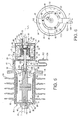
- FIG. 6 is a side elevational view of the vacuum interrupter and the solenoid of the circuit interrupting device illustrated in FIG. 1 ;
- FIG. 7 is a diagrammatic view of the electronic control of the circuit interrupting device illustrated in FIG. 1 ;
- FIG. 8 is a rear elevational view of the circuit interrupting device illustrated in FIG. 1 , showing a handle mechanism and a lever mechanism of the handle and lever mechanism assembly in the closed and normal positions, respectively;
- FIG. 9 is a top plan view of the handle and lever mechanism assembly of the circuit interrupting device illustrated in FIG. 1 , showing the handle and lever mechanisms in the closed and normal positions, respectively;
- FIG. 12 is a partial, sectional, front elevational view of the handle and lever mechanism assembly of the circuit interrupting device illustrated in FIG. 4 , showing the handle mechanism opened manually and the lever mechanism in the normal position;
- FIG. 13 is a partial, sectional, front elevational view of the handle and lever mechanism assembly of the circuit interrupting device illustrated in FIG. 4 , showing the handle mechanism in the closed position during reclose and the lever mechanism in the normal position;
- FIG. 14 is a partial, sectional, front elevational view of the handle and lever mechanism assembly of the circuit interrupting device illustrated in FIG. 4 , showing the handle mechanism in the closed position and the lever mechanism in the lock-out position.
- a circuit interrupting device 10 for a power distribution system in accordance with an embodiment of the present invention is supported by first and second insulator posts 12 and 14 mounted to a power distribution base 16 attached to cross arm or pole 17 of the system to permit electrically connecting the circuit interrupting device 10 to the system.
- circuit interrupting device 10 is used with a high voltage power distribution system, but can also be used in low voltage applications.
- Circuit interrupting device 10 generally includes a circuit interrupter 18 actuated by an actuator 20, which is electrically controlled by an electronic control assembly 22.
- Circuit interrupter 18 is preferably a vacuum interrupter, but can be any type of interrupter such as SF6 gas interrupter or a solid dielectric interrupter.
- Actuator 20 is preferably a solenoid, but can be any known electrical or mechanical actuating or operating mechanism.
- Circuit interrupting device 10 is maintained at the same potential as the distribution system by not grounding device 10 to earth ground, thereby eliminating the need for traditional grounded enclosures and additional insulation. Also, circuit interrupting device 10 is exposed and is not received in an outer container that is grounded, such as in an oil or gas filled tank. The reduction in insulative materials significantly reduces costs and provides a compact and lighter circuit interrupting device 10 than conventional devices. The compact design also allows circuit interrupting device 10 to be mounted with various circuit interrupter mountings or be retro-fitted to various existing circuit interrupter mountings of the system.
- Vacuum interrupter 18 provides voltage switching and generally includes a vacuum bottle 24 having a ceramic outer shell 26 with first and second opposing ends 28 and 30.
- a stationary or primary contact 32 is fixed at first end 28 and a movable contact 34 is slidably supported in an opening at second end 30.
- a seal (not shown) can be provided to ensure a vacuum is maintained in vacuum bottle 24.
- Contacts 32 and 34 are preferably made of a conductive material, such as copper. Vacuum is defined as being substantially evacuated of air.
- the movable contact 34 is connected to and operated by actuator or solenoid 20.
- Vacuum interrupter 18 should meet certain minimum requirements for industry standards. For example, when used in a recloser application, vacuum interrupter 18 should meet industry standards outlined in for example ANSI/IEEE C37.60 for reclosers.
- Vacuum interrupter 18 is supported by a dielectric housing 36 preferably made of a glass filled polyester.
- Housing 36 is a unitary one-piece member that is hollow and generally cylindrical in shape to accommodate vacuum interrupter 18.
- a first end 38 of housing 36 includes an opening 40 for receiving a conductive insert or first terminal 42 molded into opening 40 of housing 36.
- a bolt 43 extends through insert 42 into vacuum interrupter stationary contact 32 thereby connecting insert 42 to vacuum interrupter 18.
- Insert 42 provides a mechanism for electrically connecting stationary contact 32 and vacuum interrupter 18 directly or indirectly to the power distribution system.
- housing 36 includes a radial support plate 46 for rigidly coupling vacuum bottle 24 and solenoid 20.
- Radial support plate 46 preferably includes three leg extensions 48, as seen in FIGS.
- mounting plate 50 that connect to a mounting plate 50 via fasteners 53 for mounting solenoid 20 to radial support plate 46.
- Mounting plate 50 can either be fastened to solenoid 20, such as by screws (not shown), or made unitary with solenoid 20.
- solenoid 20 is a latching or bistable mechanism that moves movable contact 34 between and holds it in the open and closed positions with respect to stationary contact 32. Since circuit interrupting device 10 is at the same potential as the system, solenoid 20 can be directly connected adjacent to vacuum interrupter 18.
- Solenoid 20 includes a generally cylindrical housing 56 with a longitudinal shaft 58 received therein.
- Shaft 58 includes a first part 60 with a first connection end 62 for connecting to vacuum interrupter movable contact 34 and an opposite end 63 without any insulation therebetween.
- a second part 64 of shaft 58 includes a second connection end 66 remote from first connection end 62 for connecting to a manual handle and lever mechanism assembly 68, described below, for manually opening and closing vacuum interrupter 18 and an opposite end 65.
- actuating block 70 that is generally cylindrical and receives ends 63 and 65 of first and second parts 60 and 64, respectively, of shaft 58 within an inner bore 72.
- Actuating block 70 includes a first end 74 with end 63 of shaft first part 60 extending therethrough into inner bore 72. End 65 of shaft second part 64 extends through a second end 76 opposite first end 74 and into inner bore 72.
- Block second end 76 also includes a shoulder 78 that engages position limit switch 80 supported by bracket 82 for conveying the position of shaft 58 and vacuum interrupter 18, either opened or closed, to electronic control assembly 22 as block 70 slidably moves along a longitudinal axis 71 within solenoid 20.
- a first biasing member 84 is disposed in inner bore 72 between ends 63 and 65 of shaft first and second parts 60 and 64.
- First biasing member 84 is preferably a plurality of Belleville washers.
- Shaft first part 60 is trapped between vacuum interrupter movable contact 34 and first biasing member 84 of actuator block 70.
- Shaft second part 64 screws into actuating block inner bore 72 with end 65 to adjust the load applied by first biasing member 84 on shaft first part 60 by increasing or decreasing the load applied to biasing member 84 by end 65 of shaft second part 64. This allows selection of the appropriate amount of load to ensure the proper connection between shaft first part 60 and movable contact 34 and thus between vacuum interrupter stationary and movable contacts 32 and 34.
- a second biasing member 88 Disposed around the outer surface 86 of support block 70 is a second biasing member 88 which is preferably a compression spring.
- a permanent magnet 90 preferably any rare earth magnet, abuts actuating block first end 74, and holds actuating block 70 toward magnet 90 forcing shaft first part 60 and movable contact 34 against stationary 32 in the vacuum interrupter closed position.
- a radial lip 94 of actuating block 70 compresses spring 88, as seen in Fig. 5 .
- the permanent magnet 90 and flux concentrator 91 allow the solenoid 20 to hold the vacuum interrupter contacts 32 and 34 closed without power.
- An energy coil 92 surrounds actuator block 70 and spring 88.
- Coil 92 creates an opposing magnetic force to magnet 90, releasing spring 88 and actuator block 70 away from magnet 90 when energized by electronic control assembly 22 in a first direction.
- spring 88 abuts radial lip 94 of actuating block 70 to force block 70 away from magnet 90 and vacuum interrupter 18. This in turn moves movable contact 34 away from stationary contact 32 to the open position.
- Coil 92 can also create a magnetic force in the same direction as magnet 90 which overcomes spring 88 and moves contact 34 back to the closed position when energized by electronic control assembly 22 in a second direction opposite the first direction.
- Solenoid 20 is received within a housing 106, as best seen in FIG. 4 .
- Housing 106 includes first and second halves 108 and 110 shaped to accommodate solenoid 20 with vacuum interrupter 18 connected to housing 106 by radial support plate 46 of dielectric housing 36.
- radial support plate 46 includes a plurality of threaded holes 112, which may include threaded inserts (not shown), as best seen in FIG. 6 , that align with holes (not shown) of housing 106.
- Fasteners extend through holes 112 of radial support plate 46 and the holes of conductive housing 106.
- Leg extensions 48 of radial support plate 46 extend through an opening in a first side 114 of housing 106 so that radial support plate 46 abuts side 114 thereby closing off the opening.
- a second side 116 of housing 106 opposite side 114 and dielectric housing 36 includes a conductive extension or second terminal 118.
- housing 106 is made of a conductive material forming part of the electrical connection between second terminal 118 and first terminal 42.
- Housing 106 can be made of any conductive material such as aluminum.
- housing 106 can be made of a non-conductive material, such as plastic, or a poor conductive material, such as stainless steel, with a conductive shunt (not shown) connected to second terminal 118 and electrically connected indirectly to first terminal 42.
- a flexible conductive strap 120 preferably formed of thin copper ribbons, directs the current from vacuum interrupter 18 to electronic control 22 and substantially prevents the current from going through solenoid 20.
- Strap 120 includes opposite first and second ends 122 and 124 and each end having an opening or cutout 126, as seen in FIG. 6 (showing only second end 124 with cutout 126).
- First end 122 of strap 120 is coupled to vacuum interrupter 18 and solenoid 20 at adapter 96.
- strap first end 122 is sandwiched between adapter 96 and a nut 128 with shaft first part 60 extending through the cutout of strap first end 122.
- a battery 150 is preferably used as a power source for electronic control assembly 22 to close vacuum interrupter contacts 32 and 34 when initially installing device 10 and after lock-out of device 10 due to a permanent fault.
- Battery 150 is also received within housing 106 and removably secured thereto.
- Battery 150 includes a plastic tube 152 that carries a plurality of lithium batteries and provides a current path through housing 106 to electronics board 132.
- a ring 154 at the distal end of battery 150 extends outside of conductive housing 106 and provides an attachment point for a tool, such as a hot stick, for installing and removing battery 150.
- An external power source can be used in lieu of the battery to close the interrupter contacts upon initial installation and lock-out.
- a counter mechanism 156 Also connected to electronics board 132 and received within housing 106 is a counter mechanism 156, as seen in FIG. 4 . Since most fault currents are temporary, a variable time period generally ranging between 0 and 60 seconds, such as for example 4 seconds, is programmed into electronics board 132 of electronic control 22 for closing vacuum interrupter 18, thereby reclosing the current path of the system. However, if a fault current is still detected by electronic control 22 after several operations of solenoid 20 and vacuum interrupter 18, electronic control 22 will maintain vacuum interrupter 18 in an open or lock-out position, thereby isolating the fault current from the rest of the system.
- a counter mechanism 156 tracks the number of times vacuum interrupter 18 is opened and closed independently of electronic control 22.
- manual handle and lever mechanism assembly 68 is coupled to solenoid 20 and received within housing 106.
- Manual handle and lever mechanism assembly 68 includes an operating handle mechanism 160 and a lock out lever mechanism 162.
- Operating handle mechanism 160 communicates with electronic control 22, preferably through limit switches, to allow a lineman to open vacuum interrupter 18, if necessary to interrupt the circuit, by manually rotating a handle 164 of handle mechanism 160.
- Handle 164 will also provide a visual indication of when device 10 and contacts 32 and 34 are closed or in permanent lock-out.
- Lock-out lever mechanism 162 allows the lineman to prevent electronic control 22 from signaling solenoid 20 and vacuum interrupter 18 to reclose after a fault current has been detected by manually rotating a lever 166 of lever mechanism 162. This is particularly useful when the lineman is testing or performing maintenance on the system to prevent reclosure while work is being performed.
- Handle mechanism 160 and lever mechanism 162 operate independently of one another.
- Handle mechanism 160 includes handle 164 connected to a rotatable shaft 168 which supports a drive spring 170 that is loaded when handle 164 is in the normal or closed position, as seen in FIG. 8 .
- Drive spring 170 is preferably a double torsion spring.
- Mechanism 160 also includes a secondary solenoid assembly 172 supported by a bracket 175 (seen in FIGS. 9 and 10 ). When secondary solenoid assembly 172 is stimulated by electronic control 22 that fault conditions are present and permanent (i.e. not temporary), solenoid assembly 172 releases the stored energy in drive spring 170 to move handle 164 about seventy degrees downwardly to the open position indicating that vacuum interrupter 18 is in the open position.
- At least one nut or catch 195 is disposed at shaft connection end between U-shaped bracket 192 and pin 196 to engage U-shaped bracket 192 for mechanically pulling solenoid shaft 58 and actuator block 70 in response to the lineman rotating the handle which in turn pulls vacuum interrupter movable contact 34 out of contact with stationary contact 32 when the electronic control is inoperative.
- circuit interrupting device 10 is assembled by rigidly coupling vacuum interrupter 18 and solenoid 20 using adapter 96. Specifically, adapter first end 98 is threaded into the end 100 of vacuum interrupter movable contact 34 and connection end 62 of solenoid shaft first part 60 is threaded into adapter second end 102. Solenoid 20 will be adjacent vacuum interrupter 18 and no insulation is placed in the connection between movable contact 34 and shaft first part 60 since circuit interrupting device 10 will be maintained at system potential and not grounded. This allows for a compact design of circuit interrupting device 10. Also, mounting plate 50 attached to solenoid 20 is mounted to leg extensions 48 of radial support plate 46 of vacuum interrupter dielectric housing 36 via fasteners 53, such as screws.
- Dielectric housing 36 is connected to housing 106, with solenoid 20, electronic control 22 and handle and lever mechanism assembly 68 being received within housing 106.
- dielectric housing 36 is attached to housing 106 by aligning threaded holes 112 of radial support plate 46 with holes in housing 106 allowing fasteners, such as screws, to be inserted and threaded therein thereby coupling dielectric housing 36 and conductive housing 106.
- Handle 164 and lever 166 of handle and lever mechanism assembly 68 extend outside of housing 106 and can include a protective cover 212, as seen in FIGS. 2 and 3 .
- the assembled circuit interrupting device 10 can be mounted in a variety of mountings of the power distribution system as long as first and second terminals 42 and 118 of device 10 are electrically connected to the system.
- circuit interrupting device 10 is mounted between posts 12 and 14 of a conventional switching device (switch not shown).
- first and second terminals 42 and 118 are engaged with first and second brackets 208 and 210 of posts 12 and 14, respectively, thereby supporting circuit interrupting device 10 and electrically connecting circuit interrupting device 10 to the system.
- the engagement of first and second terminals 42 and 118 with brackets 208 and 210, respectively, allow for easy installation of device 10 as well as removal of device 10. This allows a lineman to completely remove circuit interrupting device 10 from the system, such as for maintenance, and once removed also provides a clear visual indication that the circuit has been interrupted.
- Capacitor 140 provides an energy pulse to coil 92 of solenoid 20 in a first direction that cancels magnetic force of magnet 90 of solenoid 20, thereby releasing compression spring 88 and actuator block 70. Due to the force of spring 88 on actuator block 70, block 70 and shaft 58 will move away from magnet 90 and vacuum interrupter 18. Since first part 60 of shaft 58 is connected to movable contact 34 of vacuum interrupter 18, movable contact 34 will separate from stationary contact 32 to the open position thereby breaking the current path and interrupting the fault.
- the second capacitor 142 is triggered via microcontroller 148 and switch 146 to provide an energy pulse in a second direction, opposite the first direction of the first capacitor 140, to coil 92 which creates a magnetic force that overcomes the spring 88 thereby moving actuator block 70 back against magnet 90 and movable contact 34 back into contact with stationary contact 32 to the closed position, thereby reclosing the current path. If after several of these operations, the fault conditions remain, electronic control 22 will trigger solenoid 20 and vacuum interrupter contacts 32 and 34 to remain in the open or lock-out position, thereby permanently isolating the fault from the system.
- Microcontroller 148 includes a memory for recording data after a fault has occurred such as the amplitude of the fault current, the duration of the fault current, the number of reclose operations performed, the time of day, and the date. This data can then be downloaded. Preferably, microcontroller 148 continually stores the last 12 events.
- Handle and lever mechanism assembly 68 is shown in the normal operating position, as seen in FIGS. 4 , and 8-10 , when vacuum interrupter contacts 32 and 34 are in the closed position.
- handle 164 of handle mechanism 160 is in the closed position or extending horizontally with respect to housing 106 and lever 166 is the normal position or extending horizontally in a direction opposite that of handle 164, as seen in FIG. 8 .
- Drive spring 170 is loaded and restrained by lever 178 and housing plate 179.
- Lever 178 is restrained under retainer block 176 of secondary solenoid assembly 172.
- Compression spring 182 of over toggle spring assembly 180 biases handle shaft 168 and handle 164 in the closed position.
- lever 200 of lever mechanism 162 engages switch 202 which signals electronic control 22 to operate under normal reclose conditions.
- Over toggle spring 206 biases lever 200 toward switch 202 and lever 166 in the normal position.
- handle and lever mechanism assembly 68 is shown in a position after a fault current is determined to be permanent and electronic control 22 signaled vacuum interrupter contacts 32 and 34 (seen in FIG. 5 ) to remain permanently in the open or lock-out position.
- electronic control 22 signaled solenoid 174 of solenoid assembly 172 to release the stored energy of drive spring 170 by retracting retaining block 176 allowing lever 178 to rotate with respect to handle shaft 168 upwardly toward drive spring 170 to release drive spring 170.
- Pin 181 engaged lever 178 which in turn rotated handle shaft 168 and handle 164 to the open position (not shown) with handle 164 extending vertically downwardly with respect to housing 106.
- handle and lever mechanism assembly 68 is shown in a position after a lineman has manually moved handle mechanism 160 to the open position by rotating handle 164 downwardly to a vertical position (not shown). Rotation of handle 164 will cause cam 188 on handle shaft 168 (seen in FIG. 10 ) to trigger switch 186 which communicates with electronic control 22 (seen in FIG. 4 ) to open solenoid 20 and vacuum interrupter contacts 32 and 34 (seen in FIG. 5 ).
- Drive spring 170 remains loaded and lever 178 is retained under retaining block 176 of solenoid assembly 172. If electronic control 22 has malfunctioned, shaft 168 of handle mechanism 160 rotates U-shaped bracket 192 which engages nut or catch 195 (seen in FIG.
- lever 166 of lever mechanism 162 is maintained in its normal position, as seen in FIG. 8 .
- a circuit interrupting device for use with an electrical power distribution system, comprising: circuit interrupter including a primary contact and a movable contact movable relative to said primary contact between a closed position allowing current to pass through said circuit interrupter and an open position separating said contacts and preventing current from passing through said circuit interrupter; an actuator coupled to said circuit interrupter, said actuator including a shaft coupled to said movable contact of said circuit interrupter for substantially simultaneous movement without insulation being disposed between said shaft and said movable contact, said shaft moving said movable contact from said closed position to said open position upon occurrence of a fault current; and an electronic control electrically connected to said actuator and communicating with said actuator to trigger said shaft to move said movable contact of said circuit interrupter from said closed position to said open position.
- a circuit interrupting device wherein said electronic control includes first and second capacitors that provide energy to said actuator in first and second opposing directions, respectively, with said first and second directions corresponding to shaft movement towards said closed and open positions.
- a circuit interrupting device wherein said dielectric housing of said circuit interrupter and said housing of said actuator are ungrounded.
- a circuit interrupting device wherein a wire strap is disposed between said circuit interrupter and said electronic control to direct the current path therebetween and isolate said actuator from the current path.
- a circuit interrupting device according to statement 1, wherein said movable contact and said shaft are coupled by a mechanical connection.
- circuit interrupting device is a vacuum interrupter that includes a substantially vacuum enclosure that encloses said movable contact and said primary contact.
- a circuit interrupting device wherein a rotating handle is coupled to said shaft and is movable between first and second positions for mechanically moving said movable contact from said closed position to said open position.
- a circuit interrupting device wherein said handle includes a handle shaft with a bracket pivotally connected to said shaft of said actuator; and said handle is axially spaced from said shaft of said actuator.
- a circuit interrupting device wherein said electronic control is electrically connected to said handle for selectively moving said handle between said first and second positions substantially simultaneously with moving said movable contact between said closed and open positions.
- a circuit interrupting device according to statement 1, wherein said electronic control is programmable.
- a circuit interrupting device according to statement 19, wherein said electronic control stores data related to the fault current.
- a circuit interrupting device according to statement 1, wherein a power source is removably and electrically connected to said electronic control to supply power to said electronic control and to be at the same potential as said circuit interrupter.
- a circuit interrupting device according to statement 21, wherein said power source is a battery.
- a circuit interrupting device according to statement 1, wherein said electronic control comprises a current transformer at line potential as a power source.
- a circuit interrupting device for use with an electrical power distribution system, comprising: a circuit interrupter having a closed position allowing current to pass through said circuit interrupter and an open position preventing current from passing through said circuit interrupter; an actuator electrically and mechanically coupled to said circuit interrupter, said actuator moves said circuit interrupter between said closed and open positions upon occurrence of a fault current; and first and second terminals electrically connected to said circuit interrupter and being adapted for electrical connection to the power distribution system, defining a current path between said first terminal, said circuit interrupter, and said second terminal, allowing current of the power distribution system to pass through said current path so that the potential of said circuit interrupter is the same as the potential of the power distribution system, whereby said circuit interrupter and said actuator are not mounted in a grounded container, and said first terminal, said circuit interrupter, said actuator, and said second terminal being ungrounded.
- a circuit interrupting device wherein said circuit interrupter includes a primary contact and a movable contact that moves relative to said primary contact between said closed positions and said open position; and said actuator includes a shaft coupled to said movable contact for substantially simultaneous movement with said movable contact between said closed and open positions.
- a circuit interrupting device wherein an electronic control is electrically connected to each of said circuit interrupter and said actuator, respectively, said electronic control communicates with said actuator to move said movable contact of said circuit interrupter from said closed position to said open position upon occurrence of the fault current.
- a circuit interrupting device wherein said circuit interrupter is supported by a dielectric housing; and said actuator is received in a housing, said housing of said actuator is coupled to said dielectric housing of said circuit interrupter.
- a circuit interrupting device according to statement 28, wherein said housing of said actuator is made of a conductive material.
- a circuit interrupting device according to statement 28, wherein said dielectric housing of said circuit interrupter and said housing of said actuator are ungrounded.
- a circuit interrupting device wherein said first terminal extends from said circuit interrupter; and said second terminal extends from said housing of said actuator remote from said first terminal.
- a circuit interrupting device according to statement 24, wherein said actuator is a solenoid.
- a circuit interrupting assembly for an electrical power distribution system comprising: a first insulator adapted for connection to the power distribution system, said insulator has a first conductive bracket; and a circuit interrupting device coupled to said first conductive bracket of said insulator, said circuit interrupting device including, a circuit interrupter including a dielectric housing with a primary contact and a movable contact enclosed therein, said movable contact being movable relative to said primary contact between a closed position allowing current to pass through said circuit interrupter and an open position separating said contacts and preventing current from passing through said circuit interrupter, an actuator coupled to and disposed adjacent to said circuit interrupter, said actuator being received in a housing and including a shaft coupled to said movable contact of said circuit interrupter for substantially simultaneous movement without insulation being disposed between said shaft and said movable contact, said shaft moves said circuit interrupter between said closed and open positions upon occurrence of a fault current, and first and second terminals electrically connected to said circuit interrupter contacts, and at least one of said first and second terminals
- a circuit interrupting assembly according to statement 34, wherein said first and second terminals are removably coupled to said first and second conductive brackets, respectively, allowing complete removal of said circuit interrupting device thereby providing a visual interruption in said current path.
- a circuit interrupting assembly according to statement 36, wherein said housing of said actuator is formed of a conductive material and electrically connected to said second terminal so that the current path is defined through said housing of said actuator.
- a circuit interrupting assembly according to statement 37 wherein said dielectric housing is formed of a polyester material; and said conductive housing is formed of aluminum.
- a circuit interrupting assembly according to statement 33, wherein an electronic control is received in said housing of said actuator and is electrically connected to said actuator, said electronic control communicates with said actuator to trigger said shaft to move said movable contact of said circuit interrupter from said closed position to said open position upon occurrence of the fault current.
- a recloser for use with an electrical power distribution system comprising: a circuit interrupter including a primary contact and a movable contact movable relative to said primary contact between a closed position allowing current to pass through said circuit interrupter and an open position separating said contacts and preventing current from passing through said circuit interrupter; an actuator coupled to said circuit interrupter, said actuator including a movable shaft coupled to said movable contact of said circuit interrupter for substantially simultaneous movement therewith and without insulation being disposed between said movable contact and said movable shaft; and an electronic control electrically connected to said actuator, said electronic control communicating with said actuator upon occurrence of a fault current to trigger said shaft to move said movable contact of said circuit interrupter from said closed position to said open position and to trigger said shaft to reclose said movable contact from said open position to said closed position upon termination of the fault current.
- circuit interrupter includes a dielectric housing enclosing said movable contact; each of said actuator and said electronic control are received in a housing with said dielectric housing connected to said housing of said actuator and said electronic control.
- first and second terminals are electrically connected to each of said circuit interrupter and said electronic control, respectively, and adapted for electrical connection to the power distribution system, and define a current path between said first terminal, said circuit interrupter, said electronic control and said second terminal, allowing current of the power distribution system to pass through said current path so that the potential of each of said circuit interrupter, said electronic control, respectively, is the same as the potential of the power distribution system, and said first terminal, said circuit interrupter, said actuator, and said second terminal, being ungrounded.
- first and second terminals are electrically connected to said circuit interrupter and said electronic control, respectively, and are remote from one another, said first and second terminals are adapted for removable connection to the power distribution system allowing complete removal of said circuit interrupter, said actuator, and said electronic control from the power distribution system thereby providing a visible break in said current path.
- a recloser for use with an electrical power distribution system comprising: a circuit interrupter movable between a closed position allowing current to pass through said circuit interrupter and an open position preventing current from passing through said circuit interrupter; an actuator coupled to said circuit interrupter and moving said circuit interrupter between said closed and open positions; a rotatable handle mechanism coupled to said actuator and movable between first and second positions corresponding to said closed and open positions of said circuit interrupter, respectively; and an electronic control electrically connected to each of said actuator and said handle mechanism for said electronic control to trigger said actuator to move said circuit interrupter from said closed position to said open position and for said handle mechanism to trigger said electronic control to cause said actuator to move said circuit interrupter from said open position to said closed position upon movement of said handle from said second position to said first position, said handle mechanism upon movement from said second position to said first position being incapable of mechanically moving said circuit interrupter to said closed position.
- said circuit interrupter includes a primary contact and a movable contact movable relative to said primary contact between said closed position with said contacts being in contact and said open position with said contacts being separated;
- said actuator includes a shaft coupled to said movable contact for substantially simultaneous movement with said movable contact; and said handle mechanism is coupled to said shaft for mechanically moving said actuator from said closed position to said open position.
- a recloser according to statement 52 wherein said handle mechanism includes a bracket slidably coupled to said shaft allowing said shaft to slide between said closed and open positions; and said shaft includes a catch that can engage said bracket when said handle mechanism is mechanically moved from said first position to said second position to move said actuator mechanically from said closed position to said open position without operation of said electronic control.
- a recloser according to statement 51 wherein said electronic control substantially simultaneously triggers said actuator to move said circuit interrupter from said closed to said open position and moves said handle mechanism from said first position to said second position during permanent fault conditions.
- a recloser according to statement 51 wherein a lever mechanism separate from said handle mechanism is electrically connected to said electronic control for preventing said electronic control from triggering said circuit interrupter and said actuator to reclose from said open position to said closed position.
- lever mechanism includes a lever and a rotatable shaft whereby rotating of said lever and said rotatable shaft triggers said electronic control to prevent said circuit interrupter and said actuator from reclosing from said open position to said closed position.
Landscapes
- Physics & Mathematics (AREA)
- Electromagnetism (AREA)
- Driving Mechanisms And Operating Circuits Of Arc-Extinguishing High-Tension Switches (AREA)
- Emergency Protection Circuit Devices (AREA)
- Breakers (AREA)
- Gas-Insulated Switchgears (AREA)
Applications Claiming Priority (3)
| Application Number | Priority Date | Filing Date | Title |
|---|---|---|---|
| US29458301P | 2001-06-01 | 2001-06-01 | |
| US10/117,338 US6753493B2 (en) | 2001-06-01 | 2002-04-08 | Electrical circuit interrupting device |
| EP02737261.4A EP1402548B1 (de) | 2001-06-01 | 2002-05-30 | Unterbrechungseinrichtung für eine elektrische schaltung |
Related Parent Applications (3)
| Application Number | Title | Priority Date | Filing Date |
|---|---|---|---|
| EP02737261.4A Division EP1402548B1 (de) | 2001-06-01 | 2002-05-30 | Unterbrechungseinrichtung für eine elektrische schaltung |
| EP02737261.4A Division-Into EP1402548B1 (de) | 2001-06-01 | 2002-05-30 | Unterbrechungseinrichtung für eine elektrische schaltung |
| EP02737261.4 Division | 2002-05-30 |
Publications (3)
| Publication Number | Publication Date |
|---|---|
| EP2256774A2 true EP2256774A2 (de) | 2010-12-01 |
| EP2256774A3 EP2256774A3 (de) | 2014-05-14 |
| EP2256774B1 EP2256774B1 (de) | 2016-11-09 |
Family
ID=26815179
Family Applications (3)
| Application Number | Title | Priority Date | Filing Date |
|---|---|---|---|
| EP02737261.4A Expired - Lifetime EP1402548B1 (de) | 2001-06-01 | 2002-05-30 | Unterbrechungseinrichtung für eine elektrische schaltung |
| EP10176841.4A Expired - Lifetime EP2256775B1 (de) | 2001-06-01 | 2002-05-30 | Unterbrechungseinrichtung für eine elektrische schaltung |
| EP10176837.2A Expired - Lifetime EP2256774B1 (de) | 2001-06-01 | 2002-05-30 | Unterbrechungseinrichtung für eine elektrische schaltung |
Family Applications Before (2)
| Application Number | Title | Priority Date | Filing Date |
|---|---|---|---|
| EP02737261.4A Expired - Lifetime EP1402548B1 (de) | 2001-06-01 | 2002-05-30 | Unterbrechungseinrichtung für eine elektrische schaltung |
| EP10176841.4A Expired - Lifetime EP2256775B1 (de) | 2001-06-01 | 2002-05-30 | Unterbrechungseinrichtung für eine elektrische schaltung |
Country Status (9)
| Country | Link |
|---|---|
| US (3) | US6753493B2 (de) |
| EP (3) | EP1402548B1 (de) |
| AU (5) | AU2002310200B2 (de) |
| BR (1) | BRPI0210117B1 (de) |
| CA (1) | CA2448487C (de) |
| MX (1) | MXPA03010815A (de) |
| TW (1) | TW552608B (de) |
| WO (1) | WO2002099826A1 (de) |
| ZA (1) | ZA200309203B (de) |
Families Citing this family (79)
| Publication number | Priority date | Publication date | Assignee | Title |
|---|---|---|---|---|
| JP4135870B2 (ja) * | 2002-04-16 | 2008-08-20 | 株式会社日立製作所 | 真空スイッチ |
| NL1020581C2 (nl) * | 2002-05-13 | 2003-11-14 | Holec Holland Nv | Schakelinstallatie voorzien van elektrisch isolerende barriÞre. |
| US6936779B2 (en) * | 2003-08-28 | 2005-08-30 | Hubbell Incorporated | Bypass recloser assembly |
| CN100367588C (zh) * | 2004-03-01 | 2008-02-06 | 株式会社东芝 | 固体绝缘开关设备、树脂模制品及该树脂模制品的制造方法 |
| US20060001497A1 (en) * | 2004-07-01 | 2006-01-05 | Minteer Timothy M | Magnetic actuator trip and close circuit and related methods |
| AR047212A1 (es) * | 2004-08-03 | 2006-01-11 | Coesp Ltda Componentes Eletric | Metodo para seccionar con un seccionador una linea de distribucion de energia electrica de media tension que presenta una pertubacion, seccionador de lineas de distribucion de energia electrica de media tension de aplicacion en el mismo y circuito electronico de deteccion de una corriente de falla c |
| US6930271B1 (en) * | 2004-08-13 | 2005-08-16 | Eaton Corporation | Circuit interrupter including linear actuator and manual pivot member |
| US7495574B2 (en) * | 2004-09-03 | 2009-02-24 | Cooper Technologies Company | Electrical system controlling device with wireless communication link |
| DE102004047276B4 (de) | 2004-09-24 | 2006-11-30 | Siemens Ag | Selbsthaftende Elastomerschicht in feststoffisolierten Schalterpolen |
| JP4612407B2 (ja) * | 2004-12-22 | 2011-01-12 | 株式会社東芝 | 開閉装置 |
| AU2006306689B2 (en) † | 2005-10-27 | 2011-10-06 | S & C Electric Company | Circuit testing closer apparatus and method with in-rush current awareness |
| US7672108B2 (en) * | 2005-10-28 | 2010-03-02 | S & C Electric Company | Fault interrupter and disconnect device |
| EP2372741B1 (de) | 2005-11-28 | 2014-01-29 | S & C Electric Company | Verfahren zur Bestimmung des Lebensendes eines Vakuumschalters |
| US7545245B2 (en) * | 2006-05-01 | 2009-06-09 | Eaton Corporation | Manual opening device and electrical switching apparatus employing the same |
| US7534976B2 (en) * | 2006-06-26 | 2009-05-19 | Fci Americas Technology, Inc. | Vacuum recloser |
| US7869170B2 (en) * | 2006-07-14 | 2011-01-11 | Susan Jean Walker Colsch | Method and system for time synchronized trip algorithms for breaker self protection |
| US20080180866A1 (en) * | 2007-01-29 | 2008-07-31 | Honor Tone, Ltd. | Combined arc fault circuit interrupter and leakage current detector interrupter |
| US8630688B2 (en) * | 2007-03-16 | 2014-01-14 | Siemens Energy, Inc. | Winding for use in high temperature superconducting generator |
| DE102007018344B4 (de) * | 2007-04-16 | 2022-08-04 | Siemens Energy Global GmbH & Co. KG | Vorrichtung zum Schutz von Umrichtermodulen |
| US7630189B2 (en) * | 2007-05-17 | 2009-12-08 | Energie H.T. International Inc. | High voltage disconnecting switch control |
| US7999416B2 (en) * | 2008-04-14 | 2011-08-16 | Emergie H. T. International Inc. | Module for controlling a switch in a high voltage electrical substation |
| US8941960B2 (en) * | 2008-10-22 | 2015-01-27 | Siemens Ltd. | Electrical switching apparatus |
| WO2010096290A1 (en) * | 2009-02-17 | 2010-08-26 | Abb Technology Ag | Manual tripping device for circuit breaker |
| EP2270823B1 (de) * | 2009-07-01 | 2012-02-08 | ABB Technology AG | Spannungsschütz mit Mehrphasenmedium |
| DE102009040692B4 (de) * | 2009-09-04 | 2019-03-21 | Siemens Aktiengesellschaft | Leistungsschalter |
| EP2312606B1 (de) * | 2009-10-14 | 2013-02-27 | ABB Technology AG | Bistabiler magnetischer Aktuator für einen Mittelspannungsschutzschalter |
| EP2337052B1 (de) | 2009-12-17 | 2017-02-22 | ABB Schweiz AG | Schaltvorrichtung und Schaltanlage |
| US8269130B2 (en) * | 2010-02-24 | 2012-09-18 | Eaton Corporation | Retainer, vacuum interrupter, and electrical switching apparatus including the same |
| US8178801B2 (en) * | 2010-03-29 | 2012-05-15 | Eaton Corporation | Electrical switching apparatus including a carrier, and pole for the same |
| CN101908435B (zh) * | 2010-08-05 | 2012-12-19 | 西安通大思源电器有限公司 | 一种永磁操动的真空断路器 |
| CN102013355B (zh) * | 2010-08-05 | 2013-05-01 | 西安通大思源电器有限公司 | 一种提高永磁操动真空断路器寿命的控制方法 |
| US8497446B1 (en) | 2011-01-24 | 2013-07-30 | Michael David Glaser | Encapsulated vacuum interrupter with grounded end cup and drive rod |
| DE102011007900A1 (de) * | 2011-04-21 | 2012-10-25 | Siemens Aktiengesellschaft | Spannungswandler für eine Schaltanlage |
| CN103608884B (zh) | 2011-06-16 | 2016-06-01 | Abb技术有限公司 | 开关装置和开关柜 |
| WO2012171569A1 (en) | 2011-06-16 | 2012-12-20 | Abb Technology Ag | A switching device and a switchgear |
| JP5579323B2 (ja) * | 2011-07-07 | 2014-08-27 | 三菱電機株式会社 | 電磁操作装置 |
| US9031795B1 (en) * | 2011-12-13 | 2015-05-12 | Finley Lee Ledbetter | Electromagnetic test device to predict a usable life of a vacuum interrupter in the field |
| USD709462S1 (en) * | 2012-03-23 | 2014-07-22 | Mitsubishi Electric Corporation | Case for vacuum circuit breaker |
| EP2847777B1 (de) * | 2012-05-07 | 2016-03-30 | S & C Electric Co. | Spannungsabfallausgleicher |
| JP5872388B2 (ja) * | 2012-06-18 | 2016-03-01 | 株式会社日立製作所 | 操作装置または真空開閉器 |
| US9679721B2 (en) | 2012-08-31 | 2017-06-13 | Hubbell Incorporated | Air break electrical switch having a blade toggle mechanism |
| US9761394B2 (en) | 2013-02-08 | 2017-09-12 | Hubbell Incorporated | Current interrupter for high voltage switches |
| US10978256B1 (en) | 2013-03-15 | 2021-04-13 | Innovative Switchgear IP, LLC | Electrical switching device |
| CN105164781B (zh) * | 2013-03-18 | 2017-09-15 | Abb技术股份公司 | 用于电流开关装置的磁致动装置 |
| JP6161354B2 (ja) * | 2013-03-25 | 2017-07-12 | 三菱電機株式会社 | 真空バルブ |
| CN103337407B (zh) * | 2013-05-30 | 2015-04-01 | 许昌南方鑫达工业有限公司 | 顺时针转动的真空断路器的传动机构 |
| DE102013216018B4 (de) * | 2013-08-13 | 2021-06-02 | Siemens Aktiengesellschaft | Vorrichtung zur Übertragung von Kräften |
| US20170006882A1 (en) | 2014-01-28 | 2017-01-12 | Unigel S.A.S. Di Claudio Zanaglio & C. | Process for the production of a bakery product |
| US9520007B2 (en) | 2014-05-05 | 2016-12-13 | James C. Stippich | Remotely operable lockout system |
| US9396896B2 (en) * | 2014-06-09 | 2016-07-19 | Eaton Corporation | Modular vacuum interruption apparatus |
| EP3317892B1 (de) * | 2015-06-30 | 2019-08-28 | Eaton Intelligent Power Limited | Kombination eines elektromagnetischen schalters, eines steuergeräts und einer externen stromversorgung |
| KR102508490B1 (ko) * | 2015-12-18 | 2023-03-10 | 주식회사 유라코퍼레이션 | 전기자동차 충전케이블 제어장치의 자동 재폐로 장치 및 방법 |
| US9640311B1 (en) * | 2016-01-26 | 2017-05-02 | Goodrich Corporation | Systems and methods for solenoid state determination |
| CN210403590U (zh) * | 2016-05-02 | 2020-04-24 | 豪倍公司 | 电路中断设备 |
| EP3285276B1 (de) * | 2016-08-19 | 2021-09-29 | General Electric Technology GmbH | Antriebstab und verfahren zur herstellung eines antriebstabs |
| KR101918237B1 (ko) * | 2017-03-28 | 2018-11-13 | 엘에스산전 주식회사 | 고속스위치 |
| US10685778B2 (en) * | 2017-04-12 | 2020-06-16 | Carte International Inc. | Intra-tank under-oil vacuum primary switches for medium voltage transformer applications |
| WO2019133611A1 (en) | 2017-12-29 | 2019-07-04 | Abb Schweiz Ag | Cutout mounted recloser |
| CO2018006379A1 (es) * | 2018-06-20 | 2018-07-10 | Celsa S A S | Dispositivo para la interrupción y reconexión automática de circuitos de media tensión instalable en bases intercambiables |
| CN108565176B (zh) * | 2018-07-03 | 2024-03-12 | 四川奇通电气成套设备有限公司 | 高抗凝露的户外无重燃真空断路器 |
| BR102018016974A2 (pt) * | 2018-08-20 | 2020-03-10 | Energisa S/A | Religador monofásico, equipotencial, autoalimentado, de baixo custo e de fácil instalação |
| FR3089342B1 (fr) * | 2018-12-04 | 2021-09-17 | Schneider Electric Ind Sas | Système d'actionnement pour une ampoule à vide |
| US11181567B2 (en) | 2019-03-22 | 2021-11-23 | Electrical Materials Company | Apparatus for isolating high impedance fault in multi-tap electrical power distribution system |
| USD907594S1 (en) * | 2019-06-06 | 2021-01-12 | Ningbo C.F Electronic Tech Co., Ltd | Electrolyzer |
| GB2585833A (en) * | 2019-07-16 | 2021-01-27 | Eaton Intelligent Power Ltd | Circuit breaker |
| WO2021045961A1 (en) * | 2019-09-06 | 2021-03-11 | S&C Electric Company | Power distribution lateral protection system and method |
| US12462998B2 (en) * | 2019-10-25 | 2025-11-04 | Eaton Intelligent Power Limited | Mounting assembly and switching system with universal mounting system |
| US11996687B2 (en) | 2020-01-24 | 2024-05-28 | Hubbell Incorporated | PWM control for power distribution circuit interrupting devices |
| EP4128303A4 (de) | 2020-03-31 | 2024-04-17 | Hubbell Incorporated | System und verfahren zum betreiben eines elektrischen schalters |
| US11728117B2 (en) | 2020-09-04 | 2023-08-15 | Eaton Intelligent Power Limited | Switching apparatus with electrically isolated user interface |
| US11552466B2 (en) * | 2020-09-30 | 2023-01-10 | S&C Electric Company | Method for restoring power in an underground radial loop network |
| US12355194B2 (en) | 2021-04-07 | 2025-07-08 | Eaton Intelligent Power Limited | Electrical connector for a medium-power or high-power electrical distribution network |
| US12451313B2 (en) | 2021-04-07 | 2025-10-21 | Eaton Intelligent Power Limited | Current interrupting module with a resettable current interruption device |
| IT202100011870A1 (it) * | 2021-05-10 | 2022-11-10 | Univ Degli Studi Roma La Sapienza | Dispositivo meccatronico di comando |
| DE102021112268A1 (de) * | 2021-05-11 | 2022-11-17 | Bayerische Motoren Werke Aktiengesellschaft | Schalteinrichtung für ein mehrpoliges Hochvolt-Bordnetz eines elektrisch antreibbaren Kraftfahrzeugs, elektronische Steuereinheit sowie Kraftfahrzeug |
| US12494335B2 (en) | 2021-12-02 | 2025-12-09 | Eaton Intelligent Power Limited | Control system for separable load-break electrical connectors |
| US12094670B2 (en) * | 2022-02-22 | 2024-09-17 | S&C Electric Company | Snap together assembly for vacuum interrupter drive rod |
| US12580378B2 (en) * | 2022-10-11 | 2026-03-17 | S&C Electric Company | Point on wave polarity detection method for saturation mitigation |
| WO2025137287A1 (en) * | 2023-12-22 | 2025-06-26 | Hubbell Incorporated | Sparkless fuse |
Citations (7)
| Publication number | Priority date | Publication date | Assignee | Title |
|---|---|---|---|---|
| US4323871A (en) | 1980-03-21 | 1982-04-06 | A. B. Chance Company | Circuit protecting apparatus including resettable vacuum fuse and switch |
| US4568804A (en) | 1983-09-06 | 1986-02-04 | Joslyn Mfg. And Supply Co. | High voltage vacuum type circuit interrupter |
| US5099382A (en) | 1990-01-11 | 1992-03-24 | A. B. Chance Company | Electrical recloser having external mounting arrangement for electronics assembly |
| US5103364A (en) | 1990-01-11 | 1992-04-07 | A. B. Chance Company | Recloser apparatus |
| US5175403A (en) | 1991-08-22 | 1992-12-29 | Cooper Power Systems, Inc. | Recloser means for reclosing interrupted high voltage electric circuit means |
| US5663712A (en) | 1994-12-30 | 1997-09-02 | Hubbell Incorporated | Electrical contact position indicator assembly |
| US6242708B1 (en) | 2000-01-03 | 2001-06-05 | Eaton Corporation | Isolator switch |
Family Cites Families (43)
| Publication number | Priority date | Publication date | Assignee | Title |
|---|---|---|---|---|
| US559792A (en) * | 1896-05-12 | Of same place | ||
| JPS4876064A (de) * | 1972-01-18 | 1973-10-13 | ||
| IT1047627B (it) | 1974-10-01 | 1980-10-20 | Reyrolle Parsons Ltd | Perfezionamento negli interrutto ri per alte tensioni |
| GB1525460A (en) | 1974-10-11 | 1978-09-20 | Reyrolle Parsons Ltd | High-voltage circuit-interrupters |
| US4124790A (en) | 1975-03-06 | 1978-11-07 | Mcgraw-Edison Company | Protective switch device and operating mechanism therefor |
| NL162238C (nl) | 1976-02-19 | 1980-04-15 | Hazemeijer Bv | Vacuumschakelaar met coaxiale magneetspoel. |
| US4272687A (en) * | 1979-03-05 | 1981-06-09 | Borkan William N | Power manageable circuit breaker |
| US4381435A (en) | 1981-01-02 | 1983-04-26 | General Electric Company | Vacuum circuit breaker with means for selectively latching a wipe cage |
| US4506121A (en) | 1982-11-10 | 1985-03-19 | Cooper Industries, Inc. | Anti-overload operating linkage for enclosed interlocked receptacle with safety switch or circuit breaker |
| US4503411A (en) | 1983-11-23 | 1985-03-05 | Cooper Industries | Dual plunger solenoid device |
| US4562506A (en) | 1984-02-14 | 1985-12-31 | Cooper Industries, Inc. | Distribution line powered switchgear control |
| US4680706A (en) | 1984-05-31 | 1987-07-14 | Cooper Industries, Inc. | Recloser control with independent memory |
| US4527028A (en) | 1984-06-27 | 1985-07-02 | Joslyn Mfg. And Supply Co. | Modular vacuum interrupter |
| DD226690A1 (de) | 1984-09-24 | 1985-08-28 | Buchwitz Otto Starkstrom | Schalterpol |
| US4625189A (en) | 1985-09-20 | 1986-11-25 | Cooper Industries, Inc. | Circuit recloser with actuator for trip, close and lock out operation |
| JPS63304543A (ja) | 1987-06-05 | 1988-12-12 | Hitachi Ltd | 真空遮断器 |
| US4797777A (en) | 1987-10-20 | 1989-01-10 | A. B. Chance Company | Electronic sectionalizer and mounting structure for switchgear |
| US4839481A (en) | 1988-02-16 | 1989-06-13 | Cooper Industries, Inc. | Vacuum interrupter |
| US4879441A (en) | 1988-08-04 | 1989-11-07 | Cooper Industries, Inc. | Dielectric barrier for a vacuum interrupter |
| CA1331470C (en) | 1988-09-19 | 1994-08-16 | Miguel B. Yamat | Interrupter actuator |
| US4935715A (en) | 1988-12-21 | 1990-06-19 | A. B. Chance Company | Sectionalizer with externally mounted electronic controller |
| JPH02281521A (ja) | 1989-03-16 | 1990-11-19 | Sprecher Energ Ag | 多極真空遮断器および多極真空遮断器のための絶縁支持枠 |
| US5117325A (en) | 1990-01-23 | 1992-05-26 | Cooper Industries, Inc. | Controllable recloser for power line |
| DE4021945C2 (de) * | 1990-07-10 | 1999-12-30 | Alstom Sachsenwerk Gmbh | Schaltvorrichtung zur Unterbrechung von Fehlerströmen |
| DE4133092A1 (de) * | 1991-09-30 | 1993-04-01 | Siemens Ag | Mehrpoliger vakuumschalter mit einer polantriebseinheit fuer jede vakuumschaltroehre |
| DE4210716A1 (de) | 1992-03-27 | 1993-09-30 | Siemens Ag | Mehrpoliger Vakuumschalter mit einer jede Vakuumröhre umgebenden Isolieranordnung |
| MX9304342A (es) | 1992-07-20 | 1994-04-29 | Gec Alsthom Ltd | Reconectores automaticos. |
| JPH06215672A (ja) | 1993-01-20 | 1994-08-05 | Toshiba Corp | 真空遮断器 |
| US5747766A (en) | 1993-03-16 | 1998-05-05 | Cooper Industries, Inc. | Operating mechanism usable with a vacuum interrupter |
| WO1994025973A1 (en) | 1993-04-29 | 1994-11-10 | Lindsey Manufacturing Company | Integrated electrical system |
| US5497096A (en) | 1993-07-02 | 1996-03-05 | Cooper Industries, Inc. | Faulted circuit indictor with three-dimensional display device |
| US5387772A (en) | 1993-11-01 | 1995-02-07 | Cooper Industries, Inc. | Vacuum switch |
| GB2292249A (en) * | 1994-08-04 | 1996-02-14 | Gec Alsthom Ltd | A method of activating batteries subject to electrode passivation prior to connection to feed current to a primary load |
| AUPM774694A0 (en) * | 1994-08-30 | 1994-09-22 | Photonic Technologies Pty Ltd | Split-beam fourier filter |
| US5597992A (en) | 1994-12-09 | 1997-01-28 | Cooper Industries, Inc. | Current interchange for vacuum capacitor switch |
| GB2300305B (en) * | 1995-04-27 | 1999-04-28 | Gec Alsthom Ltd | Circuit interrupter arrangement |
| KR100438526B1 (ko) * | 1995-05-15 | 2004-09-10 | 쿠퍼 인더스트리스, 인코포레이티드 | 스위치기어액츄에이터용제어장치와방법 |
| MY119298A (en) | 1996-09-13 | 2005-04-30 | Cooper Ind Inc | Encapsulated vacuum interrupter and method of making same |
| US5912604A (en) | 1997-02-04 | 1999-06-15 | Abb Power T&D Company, Inc. | Molded pole automatic circuit recloser with bistable electromagnetic actuator |
| JP3441360B2 (ja) | 1997-03-25 | 2003-09-02 | 株式会社東芝 | しゃ断器の操作装置 |
| US6144005A (en) | 1997-07-23 | 2000-11-07 | Hitachi, Ltd. | Vacuum switch and a vacuum switchgear using the same |
| US6198062B1 (en) | 1999-05-17 | 2001-03-06 | Joslyn Hi-Voltage Corporation | Modular, high-voltage, three phase recloser assembly |
| US6373015B1 (en) * | 2000-01-03 | 2002-04-16 | Eaton Corporation | Integral load connector module |
-
2002
- 2002-04-08 US US10/117,338 patent/US6753493B2/en not_active Expired - Lifetime
- 2002-05-30 AU AU2002310200A patent/AU2002310200B2/en not_active Expired
- 2002-05-30 EP EP02737261.4A patent/EP1402548B1/de not_active Expired - Lifetime
- 2002-05-30 CA CA002448487A patent/CA2448487C/en not_active Expired - Lifetime
- 2002-05-30 MX MXPA03010815A patent/MXPA03010815A/es active IP Right Grant
- 2002-05-30 BR BRPI0210117-3A patent/BRPI0210117B1/pt active IP Right Grant
- 2002-05-30 EP EP10176841.4A patent/EP2256775B1/de not_active Expired - Lifetime
- 2002-05-30 WO PCT/US2002/016966 patent/WO2002099826A1/en not_active Ceased
- 2002-05-30 EP EP10176837.2A patent/EP2256774B1/de not_active Expired - Lifetime
- 2002-05-30 TW TW091111574A patent/TW552608B/zh not_active IP Right Cessation
-
2003
- 2003-11-26 ZA ZA2003/09203A patent/ZA200309203B/en unknown
-
2004
- 2004-01-20 US US10/759,087 patent/US6794596B2/en not_active Expired - Lifetime
- 2004-01-20 US US10/759,086 patent/US6852939B2/en not_active Expired - Lifetime
-
2006
- 2006-04-21 AU AU2006201685A patent/AU2006201685B2/en not_active Expired
- 2006-04-21 AU AU2006201686A patent/AU2006201686B9/en not_active Expired
- 2006-04-21 AU AU2006201687A patent/AU2006201687B2/en not_active Expired
- 2006-04-21 AU AU2006201684A patent/AU2006201684B2/en not_active Expired
Patent Citations (7)
| Publication number | Priority date | Publication date | Assignee | Title |
|---|---|---|---|---|
| US4323871A (en) | 1980-03-21 | 1982-04-06 | A. B. Chance Company | Circuit protecting apparatus including resettable vacuum fuse and switch |
| US4568804A (en) | 1983-09-06 | 1986-02-04 | Joslyn Mfg. And Supply Co. | High voltage vacuum type circuit interrupter |
| US5099382A (en) | 1990-01-11 | 1992-03-24 | A. B. Chance Company | Electrical recloser having external mounting arrangement for electronics assembly |
| US5103364A (en) | 1990-01-11 | 1992-04-07 | A. B. Chance Company | Recloser apparatus |
| US5175403A (en) | 1991-08-22 | 1992-12-29 | Cooper Power Systems, Inc. | Recloser means for reclosing interrupted high voltage electric circuit means |
| US5663712A (en) | 1994-12-30 | 1997-09-02 | Hubbell Incorporated | Electrical contact position indicator assembly |
| US6242708B1 (en) | 2000-01-03 | 2001-06-05 | Eaton Corporation | Isolator switch |
Also Published As
| Publication number | Publication date |
|---|---|
| AU2006201685B2 (en) | 2008-03-13 |
| EP2256775A2 (de) | 2010-12-01 |
| AU2006201684A1 (en) | 2006-05-18 |
| ZA200309203B (en) | 2005-02-23 |
| TW552608B (en) | 2003-09-11 |
| WO2002099826A1 (en) | 2002-12-12 |
| US6753493B2 (en) | 2004-06-22 |
| EP1402548A4 (de) | 2005-03-16 |
| US6852939B2 (en) | 2005-02-08 |
| US20040144757A1 (en) | 2004-07-29 |
| MXPA03010815A (es) | 2004-02-17 |
| AU2006201685A1 (en) | 2006-05-18 |
| EP2256774B1 (de) | 2016-11-09 |
| AU2006201686A1 (en) | 2006-05-18 |
| BRPI0210117B1 (pt) | 2020-11-10 |
| EP2256775B1 (de) | 2016-10-26 |
| CA2448487A1 (en) | 2002-12-12 |
| BR0210117A (pt) | 2004-06-29 |
| US20040144756A1 (en) | 2004-07-29 |
| AU2002310200B2 (en) | 2006-05-04 |
| CA2448487C (en) | 2008-09-16 |
| US6794596B2 (en) | 2004-09-21 |
| EP1402548B1 (de) | 2017-07-26 |
| EP2256774A3 (de) | 2014-05-14 |
| US20020179571A1 (en) | 2002-12-05 |
| EP1402548A1 (de) | 2004-03-31 |
| AU2006201686B9 (en) | 2008-03-13 |
| AU2006201684B2 (en) | 2007-11-22 |
| AU2006201686B2 (en) | 2007-08-09 |
| AU2006201687B2 (en) | 2008-03-13 |
| EP2256775A3 (de) | 2014-05-14 |
| AU2006201687A1 (en) | 2006-05-18 |
Similar Documents
| Publication | Publication Date | Title |
|---|---|---|
| US6753493B2 (en) | Electrical circuit interrupting device | |
| AU2002310200A1 (en) | Electrical circuit interrupting device | |
| US6687110B2 (en) | Isolating circuit breaker and circuit protection arrangement | |
| EP1665314B1 (de) | Mittelspannungs-vakuum-unterbrecherschalter | |
| EP2186107B1 (de) | Schutzschalter mit mechanisch arretiertem hochgeschwindigkeits-erdungsschalter | |
| US5103364A (en) | Recloser apparatus | |
| EP2061057A2 (de) | Sekundäres Auslösesystem für einen Leistungsschalter | |
| CN1897376B (zh) | 真空绝缘开关设备 | |
| CA2633874A1 (en) | Fault interrupter and operating method | |
| US4363063A (en) | Load break switch with built-in ground fault sensing | |
| US20250246383A1 (en) | Interrupter with inverted configuration and self-unlatching mechanism | |
| AU768686B2 (en) | Isolating circuit breaker and circuit protection arrangement | |
| KR19980010112U (ko) | 차단기의 인출방지장치 |
Legal Events
| Date | Code | Title | Description |
|---|---|---|---|
| PUAI | Public reference made under article 153(3) epc to a published international application that has entered the european phase |
Free format text: ORIGINAL CODE: 0009012 |
|
| AC | Divisional application: reference to earlier application |
Ref document number: 1402548 Country of ref document: EP Kind code of ref document: P |
|
| AK | Designated contracting states |
Kind code of ref document: A2 Designated state(s): GB IE NL |
|
| 17P | Request for examination filed |
Effective date: 20110412 |
|
| RIN1 | Information on inventor provided before grant (corrected) |
Inventor name: RHEN, DAVID Inventor name: QUALLS, MICHAEL Inventor name: DAVIS, BRADLEY |
|
| PUAL | Search report despatched |
Free format text: ORIGINAL CODE: 0009013 |
|
| AK | Designated contracting states |
Kind code of ref document: A3 Designated state(s): GB IE NL |
|
| RIC1 | Information provided on ipc code assigned before grant |
Ipc: H01H 75/04 20060101ALN20140408BHEP Ipc: H01H 33/66 20060101AFI20140408BHEP Ipc: H01H 3/22 20060101ALN20140408BHEP Ipc: H01H 1/58 20060101ALN20140408BHEP |
|
| GRAP | Despatch of communication of intention to grant a patent |
Free format text: ORIGINAL CODE: EPIDOSNIGR1 |
|
| RIC1 | Information provided on ipc code assigned before grant |
Ipc: H01H 33/66 20060101AFI20160418BHEP Ipc: H01H 3/22 20060101ALN20160418BHEP Ipc: H01H 75/04 20060101ALN20160418BHEP Ipc: H01H 1/58 20060101ALN20160418BHEP |
|
| RIC1 | Information provided on ipc code assigned before grant |
Ipc: H01H 33/66 20060101AFI20160512BHEP |
|
| INTG | Intention to grant announced |
Effective date: 20160525 |
|
| RIN1 | Information on inventor provided before grant (corrected) |
Inventor name: QUALLS, MICHAEL Inventor name: DAVIS, BRADLEY Inventor name: RHEN, DAVID |
|
| GRAS | Grant fee paid |
Free format text: ORIGINAL CODE: EPIDOSNIGR3 |
|
| GRAA | (expected) grant |
Free format text: ORIGINAL CODE: 0009210 |
|
| AC | Divisional application: reference to earlier application |
Ref document number: 1402548 Country of ref document: EP Kind code of ref document: P |
|
| AK | Designated contracting states |
Kind code of ref document: B1 Designated state(s): GB IE NL |
|
| REG | Reference to a national code |
Ref country code: GB Ref legal event code: FG4D |
|
| REG | Reference to a national code |
Ref country code: IE Ref legal event code: FG4D |
|
| REG | Reference to a national code |
Ref country code: NL Ref legal event code: FP |
|
| PLBE | No opposition filed within time limit |
Free format text: ORIGINAL CODE: 0009261 |
|
| STAA | Information on the status of an ep patent application or granted ep patent |
Free format text: STATUS: NO OPPOSITION FILED WITHIN TIME LIMIT |
|
| 26N | No opposition filed |
Effective date: 20170810 |
|
| PGFP | Annual fee paid to national office [announced via postgrant information from national office to epo] |
Ref country code: GB Payment date: 20210428 Year of fee payment: 20 Ref country code: IE Payment date: 20210426 Year of fee payment: 20 |
|
| PGFP | Annual fee paid to national office [announced via postgrant information from national office to epo] |
Ref country code: NL Payment date: 20210415 Year of fee payment: 20 |
|
| REG | Reference to a national code |
Ref country code: NL Ref legal event code: MK Effective date: 20220529 |
|
| REG | Reference to a national code |
Ref country code: GB Ref legal event code: PE20 Expiry date: 20220529 |
|
| REG | Reference to a national code |
Ref country code: IE Ref legal event code: MK9A |
|
| PG25 | Lapsed in a contracting state [announced via postgrant information from national office to epo] |
Ref country code: IE Free format text: LAPSE BECAUSE OF EXPIRATION OF PROTECTION Effective date: 20220530 Ref country code: GB Free format text: LAPSE BECAUSE OF EXPIRATION OF PROTECTION Effective date: 20220529 |