EP2257257B1 - Sonde für den nachweis von flüssigkeitsauslauf mit mehreren schichten - Google Patents
Sonde für den nachweis von flüssigkeitsauslauf mit mehreren schichten Download PDFInfo
- Publication number
- EP2257257B1 EP2257257B1 EP09718638.1A EP09718638A EP2257257B1 EP 2257257 B1 EP2257257 B1 EP 2257257B1 EP 09718638 A EP09718638 A EP 09718638A EP 2257257 B1 EP2257257 B1 EP 2257257B1
- Authority
- EP
- European Patent Office
- Prior art keywords
- layer
- probe
- distal
- conductive layer
- proximal
- Prior art date
- Legal status (The legal status is an assumption and is not a legal conclusion. Google has not performed a legal analysis and makes no representation as to the accuracy of the status listed.)
- Not-in-force
Links
- 239000000523 sample Substances 0.000 title claims description 128
- 239000012530 fluid Substances 0.000 title claims description 45
- 238000001514 detection method Methods 0.000 title claims description 18
- 239000003990 capacitor Substances 0.000 claims description 40
- 238000000034 method Methods 0.000 claims description 16
- 239000000853 adhesive Substances 0.000 claims description 15
- 230000001070 adhesive effect Effects 0.000 claims description 15
- 239000000463 material Substances 0.000 claims description 12
- 238000004519 manufacturing process Methods 0.000 claims description 10
- 239000010410 layer Substances 0.000 description 153
- 239000008280 blood Substances 0.000 description 16
- 210000004369 blood Anatomy 0.000 description 16
- 238000005520 cutting process Methods 0.000 description 7
- 238000011282 treatment Methods 0.000 description 6
- 230000001954 sterilising effect Effects 0.000 description 5
- 238000004659 sterilization and disinfection Methods 0.000 description 5
- 238000003780 insertion Methods 0.000 description 4
- 230000037431 insertion Effects 0.000 description 4
- 239000002390 adhesive tape Substances 0.000 description 3
- 238000005259 measurement Methods 0.000 description 3
- 230000035515 penetration Effects 0.000 description 3
- 206010016717 Fistula Diseases 0.000 description 2
- 229920000297 Rayon Polymers 0.000 description 2
- 230000002745 absorbent Effects 0.000 description 2
- 239000002250 absorbent Substances 0.000 description 2
- 239000012790 adhesive layer Substances 0.000 description 2
- 239000000306 component Substances 0.000 description 2
- 230000003890 fistula Effects 0.000 description 2
- 229910052751 metal Inorganic materials 0.000 description 2
- 239000002184 metal Substances 0.000 description 2
- 238000001179 sorption measurement Methods 0.000 description 2
- 239000000126 substance Substances 0.000 description 2
- 238000012360 testing method Methods 0.000 description 2
- IAYPIBMASNFSPL-UHFFFAOYSA-N Ethylene oxide Chemical compound C1CO1 IAYPIBMASNFSPL-UHFFFAOYSA-N 0.000 description 1
- 208000032843 Hemorrhage Diseases 0.000 description 1
- 239000004831 Hot glue Substances 0.000 description 1
- 239000004698 Polyethylene Substances 0.000 description 1
- 239000004820 Pressure-sensitive adhesive Substances 0.000 description 1
- 206010051101 Puncture site haemorrhage Diseases 0.000 description 1
- FAPWRFPIFSIZLT-UHFFFAOYSA-M Sodium chloride Chemical compound [Na+].[Cl-] FAPWRFPIFSIZLT-UHFFFAOYSA-M 0.000 description 1
- 238000010521 absorption reaction Methods 0.000 description 1
- 238000009825 accumulation Methods 0.000 description 1
- 239000004411 aluminium Substances 0.000 description 1
- 229910052782 aluminium Inorganic materials 0.000 description 1
- XAGFODPZIPBFFR-UHFFFAOYSA-N aluminium Chemical compound [Al] XAGFODPZIPBFFR-UHFFFAOYSA-N 0.000 description 1
- 238000002617 apheresis Methods 0.000 description 1
- 238000013459 approach Methods 0.000 description 1
- 210000001367 artery Anatomy 0.000 description 1
- 230000015572 biosynthetic process Effects 0.000 description 1
- 230000000740 bleeding effect Effects 0.000 description 1
- 239000012503 blood component Substances 0.000 description 1
- 230000006835 compression Effects 0.000 description 1
- 238000007906 compression Methods 0.000 description 1
- 239000004020 conductor Substances 0.000 description 1
- 230000008021 deposition Effects 0.000 description 1
- 239000000645 desinfectant Substances 0.000 description 1
- 238000010586 diagram Methods 0.000 description 1
- 238000000502 dialysis Methods 0.000 description 1
- 238000009792 diffusion process Methods 0.000 description 1
- 238000009826 distribution Methods 0.000 description 1
- 230000005611 electricity Effects 0.000 description 1
- 239000006260 foam Substances 0.000 description 1
- 239000003292 glue Substances 0.000 description 1
- 238000001631 haemodialysis Methods 0.000 description 1
- 230000000322 hemodialysis Effects 0.000 description 1
- 238000002615 hemofiltration Methods 0.000 description 1
- 230000002209 hydrophobic effect Effects 0.000 description 1
- 238000002847 impedance measurement Methods 0.000 description 1
- 239000012535 impurity Substances 0.000 description 1
- 230000014759 maintenance of location Effects 0.000 description 1
- 239000000615 nonconductor Substances 0.000 description 1
- 238000004806 packaging method and process Methods 0.000 description 1
- 230000010412 perfusion Effects 0.000 description 1
- 238000002616 plasmapheresis Methods 0.000 description 1
- 239000011505 plaster Substances 0.000 description 1
- 229920000728 polyester Polymers 0.000 description 1
- -1 polyethylene Polymers 0.000 description 1
- 229920000573 polyethylene Polymers 0.000 description 1
- 229920000307 polymer substrate Polymers 0.000 description 1
- 238000012545 processing Methods 0.000 description 1
- 210000004243 sweat Anatomy 0.000 description 1
- 230000002792 vascular Effects 0.000 description 1
- 210000003462 vein Anatomy 0.000 description 1
Images




Classifications
-
- A—HUMAN NECESSITIES
- A61—MEDICAL OR VETERINARY SCIENCE; HYGIENE
- A61F—FILTERS IMPLANTABLE INTO BLOOD VESSELS; PROSTHESES; DEVICES PROVIDING PATENCY TO, OR PREVENTING COLLAPSING OF, TUBULAR STRUCTURES OF THE BODY, e.g. STENTS; ORTHOPAEDIC, NURSING OR CONTRACEPTIVE DEVICES; FOMENTATION; TREATMENT OR PROTECTION OF EYES OR EARS; BANDAGES, DRESSINGS OR ABSORBENT PADS; FIRST-AID KITS
- A61F13/00—Bandages or dressings; Absorbent pads
- A61F13/15—Absorbent pads, e.g. sanitary towels, swabs or tampons for external or internal application to the body; Supporting or fastening means therefor; Tampon applicators
- A61F13/42—Absorbent pads, e.g. sanitary towels, swabs or tampons for external or internal application to the body; Supporting or fastening means therefor; Tampon applicators with wetness indicator or alarm
-
- Y—GENERAL TAGGING OF NEW TECHNOLOGICAL DEVELOPMENTS; GENERAL TAGGING OF CROSS-SECTIONAL TECHNOLOGIES SPANNING OVER SEVERAL SECTIONS OF THE IPC; TECHNICAL SUBJECTS COVERED BY FORMER USPC CROSS-REFERENCE ART COLLECTIONS [XRACs] AND DIGESTS
- Y10—TECHNICAL SUBJECTS COVERED BY FORMER USPC
- Y10T—TECHNICAL SUBJECTS COVERED BY FORMER US CLASSIFICATION
- Y10T29/00—Metal working
- Y10T29/49—Method of mechanical manufacture
- Y10T29/49002—Electrical device making
- Y10T29/49117—Conductor or circuit manufacturing
Definitions
- the present invention relates to a probe for detecting a leak or the presence of an electrically conductive fluid, such as blood or plasma, and to its method of manufacture.
- the invention has an application particularly in the field of extracorporeal treatment of blood or plasma, where blood is withdrawn from and returned to the patient for the entire duration of a session.
- a fluid is injected into a cavity or body conduit of the patient or donor by means of a channel having one end connected to a source of fluid and another end connected to a tube, such as a cannula or a catheter, with a shape, a length, a flexibility or a rigidity that are chosen to facilitate penetration of the tube into a conduit or a given cavity.
- the source of fluid is formed by the vascular circuit of the patient/donor, and the fluid is the blood of the patient/donor, which blood, pumped in an artery, is caused to circulate in a blood treatment apparatus (hemodialyzer, hemofilter, plasma filter, centrifuge, etc.) and, once freed of its impurities or having a fraction of one of its components reduced, is reinjected into a vein of the patient/donor.
- a blood treatment apparatus hemodialyzer, hemofilter, plasma filter, centrifuge, etc.
- the tube which is inserted into the conduit or body cavity, is generally held in place by means of a piece of adhesive tape placed over the channel in order to bind it to the patient's body.
- the adhesive tape comes unstuck and, as a result of the movements of the patient/donor, the tube comes completely or partially out of the cavity or conduit into which it had been inserted. It can also happen that the patient/donor, who is drowsy for example, does not notice the removal of the tube from the cavity or conduit. The incident may prove fatal, especially when the fluid injected into the patient/ donor is his own blood.
- a first invention concerning detection of physiological fluid is described in the patent FR 2 737 124 of which the device is shown in Figures 1 and 2 . It is a device for detecting accidental removal of a tube (2, 3, 29) that has been inserted into a conduit or a body cavity of a patient, the tube being connected via a channel to a source (1, 21) of a fluid circulating in the direction of the tube. Said device comprises means for detecting an effusion of fluid near the site of penetration of the tube into the patient's body.
- the means for detecting an effusion of fluid comprise a probe 7 which is sensitive to a physical or chemical characteristic of the fluid, is able to emit a corresponding signal and is intended to be affixed to the patient's body near the site of penetration of the tubular body into the patient's body, and means for processing the signal (9, 10) delivered by the probe.
- the probe is, for example, a probe for measuring conductivity or impedance.
- the probe comprises two electrodes that are connected to a control housing via two conducting wires 10, the control housing being connected to acoustic or luminous alarm means (12, 15), even to occlusion means 13 for closing the channel.
- the control housing comprises means for triggering an alarm and for causing occlusion of the channel when the voltage measured between the electrodes of the probe exceeds the predetermined threshold value and/or when the kinetics of evolution of this voltage exceed a predetermined threshold value.
- the inserted tube can be the end of the venous line of an extracorporeal blood treatment circuit, as is shown in Figure 2 .
- the prior art includes the probe described in the patent US 5 557 263 and shown in Figure 3 , which discloses an apparatus for detecting the presence of electrically conductive fluids, the concept of which device is similar to that described above, and requiring the use of a probe (or sensor) composed of a pair of electrodes (96, 98) which are of identical width, are parallel to each other and are placed on an absorbent material 130, which has the shape of an elongate strip 94 and which can be wound up on itself. The user is able to unroll the strip and cut it to the desired length.
- this strip is very simple to manufacture, it has been found that its use is not optimal in terms of detecting a leak of fluid and that it does not provide sufficient comfort when applied to a patient's arm for several hours at a time. In addition, this approach is not especially suitable for supplying the probe in an individual and sterile package.
- US 6 175 310 discloses an apparatus for detecting the presence of electrically conductive fluids, of which the concept is similar to that described above, requiring the use of a probe (or sensor) in the form of a flat strip composed of a pair of electrodes which are of identical width, are extremely flat, parallel to each other and placed on a support layer.
- the electrodes can take the form of streamlined conductors placed on the strip in order to facilitate connection to the device for measuring leaks, having different spacings between the terminals.
- US 5 579 765 discloses a monitor for detecting external bleeding from a puncture site on a patient.
- the monitor is provided with a self-sticking bandage portion on one end connected by means of a flexible connecting strip to a self-sticking holder portion on an opposite end.
- the bandage portion is applied so the puncture site is visible through a transparent window provided over a central opening in the bandage portion.
- a pair of spaced apart wires encircles the central opening, extends across the connecting strip and removably secures to a portable alarm device containing a battery and alarm connected in series by means of the wires.
- the inventors have developed a probe that provides optimized detection and optimal user comfort for the patient.
- the invention provides a disposable medical probe 1 in accordance with claim 1.
- the distal zone represents the zone that will be farthest away from the electrical connector clip for forming the electrical detection circuit, while the proximal zone represents the zone that will be nearest to the electrical connector clip.
- the invention also relates to a method for the manufacture of a disposable medical probe in accordance with claim 14.
- the disposable medical probe 1 for detecting a leak of physiological fluid through an opening made in the human body, by operating in conjunction with an electrical detection circuit comprises the following layers:
- hydrophilic layer ensures adsorption and retention of the conductive fluid at the distal zone of the conductive layer. It also allows the fluid to be detected to undergo internal lateral diffusion as far as the two detection electrodes.
- the electrodes being "placed exclusively on each side of the longitudinal axis A of the conductive layer” means that the electrodes are each on one side of a longitudinal axis A contained in the plane of the electrodes and that the electrodes do not touch or cross this axis.
- the distance d between the electrodes of the proximal zone can be substantially constant.
- the probe can thus comprise a covering layer 40 intended to be in contact with the skin and on top of at least a part of the conductive layer 20.
- This layer is intended to isolate the patient's skin from the conductive layer, and to cover and protect at least the conductive layer left uncovered by the hydrophilic layer.
- the covering layer 40 does not cover the proximal end 211', 221' of the proximal part 21', 22' of each electrode, in order to permit access to each uncovered end, called the contact end 211', 221'.
- the contact surface area of this contact end is sufficient to permit electrical contact with the conductive jaws of an electrical connector clip intended to connect each probe to the electrical measurement circuit.
- the covering layer could cover these contact ends but not be glued to these contact ends.
- the edge 41 of the covering layer 40 which covers the distal zone 21'' of the conductive layer can be perpendicular to the longitudinal axis A of the electrodes.
- This edge 41 designates the proximal edge of the covering layer, which is not necessarily aligned on the contour of the electrode.
- a second covering layer could conceivably be used to cover the support layer.
- the described series of layers defines layers that are placed on one another and that are in contact with one another according to the described order of positioning.
- the longitudinal axis A of the two electrodes according to the invention can represent an axis of symmetry of the two proximal parts 21', 22' of the electrodes, hence overall of the whole conductive layer 30.
- the distal part of the electrodes is in this case entirely symmetrical with respect to the longitudinal axis A.
- the longitudinal axis A of the at least two distal electrode parts 21'', 22" can also represent an axis of symmetry of substantially the entire probe.
- the distal part of the probe is in this case entirely symmetrical with respect to the longitudinal axis A.
- the probe can be a longitudinal probe extending along the longitudinal axis (A) of the probe. This permits a secure hold along the patient's arm.
- the length L' of the proximal zone 20' of the conductive layer is greater than the length L'' of the distal zone 20'' of the conductive layer. More particularly, the length L' of the proximal zone 20' of the conductive layer is approximately twice the length L'' of the distal zone 20'' of the conductive layer.
- the materials of each layer used can be flexible materials.
- the hydrophilic layer can be composed of a material of the compress type, for example of viscose, or of viscose and polyethylene, in the form of a woven, nonwoven or foam structure. It must have a thickness sufficient to absorb fluid and to improve and accelerate the absorption of fluid present at its surface, either laterally or in the direction of its thickness. The presence of small holes through the layer makes it possible in particular to improve adsorption. The thickness and compression capacity of this layer permits better distribution, across the skin surface, of the pressure induced by the adhesive tapes of the sticking plaster type, which will be attached to the probe in order to fix it to the arm.
- the conductive layer must be as fine as possible in order to reduce the rigidity of the probe while at the same time maintaining continuous electrical conduction. It can be a laminated layer of conductive metal alone or of conductive metal on a polymer substrate; it can be made of aluminium placed on polyester.
- the proximal part of the conductive layer is long, not very wide and not very thick, and should have low rigidity in order to allow fairly easy distortion thereof so as to reduce the mechanical stresses applied to this zone and due in particular to the attachment of a device such as an electrical clip.
- the contact ends which are wider than the rest of the proximal zone, mean that the connection surface does not distort and can be easily inserted into a clip.
- the support layer can be composed of a nonwoven material. It must be as fine as possible in order to reduce rigidity and to permit contact of the probe along the entire surface of the patient's arm.
- This layer and the adhesive layer on top can be electrically insulating or have a high electrical resistance value when the probe is dry. It would also be conceivable to have a support layer that is also an absorbent layer. This layer will preferably have low extensibility in order to preserve the mechanical dimensions of the probe during the method of manufacture by assembly of the layers, since this layer has a support and transport function during manufacture.
- the covering layer can be composed of a nonwoven material.
- This layer is a layer that covers and in particular preserves the electrodes. Moreover, it prevents the electrodes from coming into contact with the patient's skin, especially when a current passes through the electrodes.
- This layer and the adhesive applied to it in order to fix it to the face of the conductive layer, act as an electrical insulator or electrical resistor of very high value in order to permit great resistance to the dry sensor (probe).
- this layer can be hydrophobic so as to prevent false alarms due to the presence of fluid between only the proximal parts of the electrodes, for example because of residues of disinfectant or because of the patient's sweat.
- the support layer and the covering layer can be composed of the same material, even of the same sheet of material.
- the two electrodes 21, 22 can be in the form of conducting strips of substantially constant width. Each of the two strips can be continuous, made in one piece.
- the adhesive used can be, for example, a hot-melt adhesive material and/or a pressure-sensitive adhesive.
- the distal part 20'' of the conductive layer exhibits an increase in the gap e between each distal electrode part 21", 22", running in the direction from the border 20A between the proximal part and the distal part to the distal end 20B of the distal part. This makes it possible to increase the "reception" area for leaking fluid in the distal zone.
- the increase in distance apart e from said border 20A to the distal end 20B can be followed by a decrease in the gap e between the distal parts of the electrodes, as is shown in Figures 6a and 6b .
- the shape of the two distal electrode parts 21", 22" can be inscribed on an ellipse, the major axis of which is preferably the longitudinal axis A of the conductive layer.
- the ellipse can be a circle in one particular case.
- the ellipse is illustrated in Figure 6a .
- the leak detection capacity seems to be greater in the case of an ellipse rather than a truncated cone shape, especially if the needle is inserted at a large angle of incidence relative to the skin.
- the reason is that cutting the distal zone in a substantially elliptical shape and/or the elliptical shape of the electrodes permits, compared to an embodiment with frustoconical electrodes and/or cutting of the distal zone in a substantially rectangular shape, a folding of the probe in the longitudinal axis A of the probe and permits better detection of the fluid. This is because the probe more easily adapts to the shape of the fistula in the patient's arm.
- the probe can have the following two zones: a proximal probe part 1' and a distal probe part 1'', where the proximal probe part 1' is superimposed with the proximal zone 20' of the conductive layer, and the distal probe part 1'' is superimposed with the distal zone 20'' of the conductive layer.
- the greater width 1'' of the distal part 1'' of the probe can be substantially twice the constant width 1' of the proximal part 1' of the probe.
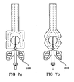
- the probe can have at least one notch 100 made on the edge of the distal part 1'' of the probe.
- at least said notch 100 is placed on an axis among the following: the longitudinal axis of the probe, and an axis perpendicular to the longitudinal axis of the probe and passing substantially through the middle of the proximal zone of the probe. As is illustrated in Figures 7a and 7b , this notch makes it possible to maintain the needle or tube inserted in the patient.
- the notch made on the edge of the probe can in fact be in the form of a half disc or of a triangle or rectangle, simply a slit, or a slit followed by an orifice, the orifice having another geometrical shape for receiving and fixing the section of the needle (1000) inserted in the patient, for example a disc.
- the probe can comprise two or three notches, or even more, depending on the position of use of the probe relative to the needle and relative to the angle of insertion of the needle.
- the probe comprises a supplementary layer called the capacitor layer 50 positioned between the support layer and the conductive layer, comprising:
- the capacitor layer permits formation of a resistor/ capacitor circuit in parallel in the area of the probe, as is illustrated in Figure 10 .
- the illustration shows that the capacitor layer 50 inserted between the conductive layer 20 and the support layer 10 will form two capacitors C1, C2: the first C1 between, on the one hand, the first electrode and the capacitor layer, and the second C2, on the other hand, the second electrode of the capacitor layer.
- the characteristics of C1 and C2 can of course be calculated by the insulating distance that separates them from the conductive layer and by their surface area.
- This supplementary layer produces, between the two contact electrodes, an electrical circuit of variable resistance R (depending on the presence of fluid) in parallel with a total capacitor.
- This phenomenon is amplified especially for 0.5 ⁇ X ⁇ 1, because of the connection in series.
- the presence of a single short circuit does not prevent the probe from functioning and detecting fluids.
- the capacitor value in the normal state will have to be fixed as high as possible, and the thickness between the two electrically active layers must be as low as possible.
- the capacitor layer 50 can be replaced by two layer elements (identical to the single capacitor layer 50 with respect to the definition of layers) placed exclusively on top of the existing electrodes 30.
- This capacitor layer alternative could be envisaged on a simple configuration comprising a support layer 10, a conductive layer 20 with two electrodes, without the conductive layer having a particular configuration as described above.
- the conductive layer could comprise two parallel electrodes as described in the prior art document US 5 557 263 . All that is described concerning this capacitor applies to this probe, and also to the probe described in US 6 175 310 .
- the insulating layer placed between the conductive layer of electrodes and the conductive layer of the capacitor can instead be replaced by an adhesive layer sufficiently thick to represent an insulating layer.
- the probe can be sterilized. It can be inserted into an individual package, and the sterilization takes place once the probe has been placed in the package.
- the sterilization can be a sterilization of the gamma sterilization type, or sterilization with ethylene oxide.
- the distal part of the probe can be a square whose side measures between approximately 30 and 40 mm.
- the distal part is an ellipse whose major axis measures approximately 40 mm and whose minor axis measures 30 mm.
- the maximum spacing e between the two distal parts of the electrodes can be equal to approximately 20 mm, the distance between two proximal parts of the electrodes can be equal to 3 mm.
- the length of the proximal zone can be equal to approximately 60 mm, the width of the proximal zone can be equal to approximately 14 mm.
- the width of the proximal parts 21' of the electrodes can be equal to 3.5 mm, the length of the contact ends of the proximal parts of the electrodes can be equal to approximately 10 mm. When the electrodes are in the form of strips the width of the strip can be equal to approximately 3.5 mm.
- the invention relates to a method for the manufacture of a disposable medical probe for detecting a leak of physiological fluid through an opening made in the human body, by operating in conjunction with an electrical detection circuit, comprising the following steps:
- the method can comprise an additional step d) which involves placing a covering layer 40, intended to come into contact with the skin, on top of at least a part of the conductive layer 20.
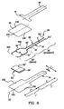
- Steps a, b, c and d are shown in Figures 5 and 9.
- Figure 9 illustrates the probe embodiment containing a supplementary layer called a capacitor layer, which would be inserted in a step c') after deposition of the conductive layer (step c).
- the method can comprise a supplementary step e) carried out after step c) or if appropriate d), as follows: cutting substantially all the edges of the probe by means of a single step of cutting the layers superimposed on one another. This single step guarantees that no accumulation of adhesive is present on the exposed outer surfaces of the probe, especially on the contact ends of the proximal zone of the electrodes.
- the method can comprise at least one of the following steps:
- This disposable probe will be disposed of at the end of the session.
- the probe according to the invention can also have the following features: a disposable medical probe 1 for detecting a leak of physiological fluid through an opening made in the human body, by operating in conjunction with an electrical detection circuit, comprising the following layers:
- the corresponding method of manufacture will be a method for the manufacture of a disposable medical probe for detecting a leak of physiological fluid through an opening made in the human body, by operating in conjunction with an electrical detection circuit, comprising the following steps:
- This method will be able to comprise the step c) of cutting substantially all the edges of the probe by means of a single step of cutting the layers superimposed on one another, which will make it possible to guarantee good reproducibility of the dimensional characteristics, especially at the zone of connections to the clip.
Landscapes
- Health & Medical Sciences (AREA)
- Epidemiology (AREA)
- Engineering & Computer Science (AREA)
- Biomedical Technology (AREA)
- Heart & Thoracic Surgery (AREA)
- Vascular Medicine (AREA)
- Life Sciences & Earth Sciences (AREA)
- Animal Behavior & Ethology (AREA)
- General Health & Medical Sciences (AREA)
- Public Health (AREA)
- Veterinary Medicine (AREA)
- Measurement And Recording Of Electrical Phenomena And Electrical Characteristics Of The Living Body (AREA)
Claims (14)
- Medizinischer Einmalsensor (1) für den Nachweis des Auslaufens einer physiologischen Flüssigkeit durch eine Öffnung, die in den menschlichen Körper eingebracht wurde, durch Zusammenarbeiten mit einer elektrischen Nachweisschaltung, der die folgenden Schichten umfasst:- eine Trägerschicht (10),- eine leitfähige Schicht (20) oben auf der Trägerschicht (10), wobei die leitfähige Schicht (20) zwei leitende Elektroden (21, 22) umfasst, die beide ausschließlich auf jeder Seite einer Längsachse platziert sind,- eine hydrophile Schicht (30), die dafür bestimmt ist, eine mögliche physiologischen Flüssigkeit aufzunehmen, oben auf zumindest einem Teil der leitfähigen Schicht (20),wobei die leitfähige Schicht (20) zwei Bereiche definiert:• einen proximalen Bereich (20'), dessen Ende mit der elektrischen Schaltung verbunden werden soll, der aus einem proximalen Teil (21', 22') jeder Elektrode (21, 22) zusammengesetzt ist, wobei die beiden proximalen Elektrodenteile (21', 22') parallel zueinander platziert und um einen Abstand (d) beabstandet sind,• einen für den Kontakt mit der möglichen Flüssigkeit bestimmten distalen Bereich (20"), der aus einem distalen Teil (21 ", 22") jeder Elektrode (21, 22) zusammengesetzt ist, wobei die beiden distalen Elektrodenteile (21', 22') bezogen auf die Längsachse symmetrisch sind und voneinander durch einen Zwischenraum (e) größer als der Abstand (d) beabstandet sind, und bei der die Längsachse (A) der mindestens zwei distalen Elektrodenteile (21 ", 22") auch eine Symmetrieachse des Sensors darstellt.
- Sensor nach Anspruch 1, bei dem die hydrophile Schicht (30) den distalen Bereich (20") der leitfähigen Schicht (20) bedeckt.
- Sensor nach einem der vorhergehenden Ansprüche, der eine Deckschicht (40) umfasst, die dafür bestimmt ist, die Haut zu berühren, oben auf zumindest einem Teil der leitfähigen Schicht (20).
- Sensor nach einem der vorhergehenden Ansprüche, bei dem die Materialien jeder verwendeten Schicht flexible Materialien sind.
- Sensor nach einem der vorhergehenden Ansprüche, bei dem eine Seite der Trägerschicht (10) mit Klebstoff bedeckt ist, um sie an einer Seite der leitfähigen Schicht (20) und an dem Teil einer Seite der hydrophilen Schicht (30) zu befestigen, der die Seite der Trägerschicht (20) direkt berührt.
- Sensor nach einem der vorhergehende Ansprüche, bei dem eine Seite der Deckschicht (40) mit Klebstoff bedeckt ist, um sie an zumindest einem Teil einer Seite des proximalen Bereichs (20') der leitfähigen Schicht zu befestigen und sie optional an einem Teil einer Seite der hydrophilen Schicht (30) zu befestigen.
- Sensor nach einem der vorhergehenden Ansprüche, bei dem der distale Teil (20") der leitfähigen Schicht eine Vergrößerung des Zwischenraums (e) zwischen jedem distalen Elektrodenteil (21 ", 22") aufweist, die in der Richtung von der Grenze (20A) zwischen dem proximalen Teil und dem distalen Teil aus zu dem distalen Ende (20B) des distalen Teils verläuft.
- Sensor nach dem vorhergehenden Anspruch, bei dem die Vergrößerung des Zwischenraums (e) zwischen jedem distalen Elektrodenteil (21 ", 22") eine Kegelstumpfform oder eine gebogene Form aufweist oder bei dem die Form der beiden distalen Elektrodenteile (21 ", 22") auf einer Ellipse einbeschrieben ist, deren Hauptachse vorzugsweise die Längsachse (A) der leitfähigen Schicht (20) ist.
- Sensor nach einem der vorhergehenden Ansprüche, der die folgenden zwei Bereiche aufweist: einen proximalen Sensorteil (1') und einen distalen Sensorteil (1 "), wobei der proximale Bereich (20') der leitfähigen Schicht über dem proximalen Sensorteil (1') liegt und der distale Bereich (20") der leitfähigen Schicht (20) über dem distalen Sensorteil (1 ") liegt.
- Sensor nach einem der vorhergehenden Ansprüche, bei dem die Ränder des distalen Teils (1 ") des Sensors eine im Wesentlichen elliptische oder rechteckige Form aufweisen.
- Sensor nach einem der vorhergehenden drei Ansprüche, bei dem mindestens eine Kerbe (100) an dem Rand des distalen Teils (1 ") des Sensors ausgeführt ist.
- Sensor nach einem der vorhergehenden Ansprüche, der eine Kondensatorschicht (50) genannte Schicht umfasst, die zwischen der Trägerschicht und der leitfähigen Schicht platziert ist, umfassend:- eine leitfähige erste Kondensatorschicht (50'), die auf der Trägerschicht (10) platziert ist,- eine isolierende zweite Kondensatorschicht (50"), die auf der leitfähigen ersten Kondensatorschicht (50') platziert ist.
- Sensor nach dem vorhergehenden Anspruch, bei dem die leitfähige erste Kondensatorschicht (50') und die isolierende zweite Kondensatorschicht (50") ein einziges Teil (50) bilden, das somit eine leitende Seite und eine isolierende Seite aufweist, und bei dem die Kondensatorschicht (50) zumindest teilweise den distalen Bereich der leitfähigen Schicht (20) bedeckt.
- Verfahren zur Herstellung eines medizinischen Einmalsensors für den Nachweis des Auslaufens einer physiologischen Flüssigkeit durch eine Öffnung, die in den menschlichen Körper eingebracht wurde, durch Zusammenarbeiten mit einer elektrischen Nachweisschaltung, umfassend folgende Schritte:a) Erhalten einer Trägerschicht (10),b) Platzieren einer leitfähigen Schicht (20) oben auf der Trägerschicht (10), wobei die leitfähige Schicht zwei leitende Elektroden (21, 22) umfasst, die beide ausschließlich auf jeder Seite einer Längsachse (A) platziert werden, wobei die leitfähige Schicht (20) zwei Bereiche definiert:• einen proximalen Bereich (20'), dessen Ende mit der Schaltung verbunden werden soll, der aus einem proximalen Teil (21', 22') jeder Elektrode zusammengesetzt wird, wobei die beiden proximalen Elektrodenteile (21', 22') parallel zueinander platziert werden und um einen im Wesentlichen gleichmäßigen Abstand (d) beabstandet werden,• einen für den Kontakt mit der möglichen Flüssigkeit bestimmten distalen Bereich (20"), der aus einem distalen Teil (21 ", 22") jeder Elektrode (21, 22) zusammengesetzt wird, wobei die beiden distalen Elektrodenteile (21", 22") bezogen auf die Längsachse symmetrisch sind und voneinander durch einen Zwischenraum (e) größer als der Abstand (d) beabstandet werden, bei der die Längsachse (A) der mindestens zwei distalen Elektrodenteile (21 ", 22") auch eine Symmetrieachse des Sensors darstellt,c) Platzieren einer hydrophilen Schicht (30), die dafür bestimmt ist, eine mögliche physiologische Flüssigkeit aufzunehmen, oben auf zumindest einem Teil der leitfähigen Schicht (20).
Applications Claiming Priority (2)
| Application Number | Priority Date | Filing Date | Title |
|---|---|---|---|
| FR0801388A FR2928551A1 (fr) | 2008-03-14 | 2008-03-14 | Sonde pour la detection de fuite de fluide a couches multiples |
| PCT/IB2009/000423 WO2009112913A1 (en) | 2008-03-14 | 2009-03-04 | Probe for fluid leak detection with multiple layers. |
Publications (2)
| Publication Number | Publication Date |
|---|---|
| EP2257257A1 EP2257257A1 (de) | 2010-12-08 |
| EP2257257B1 true EP2257257B1 (de) | 2014-01-08 |
Family
ID=40003038
Family Applications (1)
| Application Number | Title | Priority Date | Filing Date |
|---|---|---|---|
| EP09718638.1A Not-in-force EP2257257B1 (de) | 2008-03-14 | 2009-03-04 | Sonde für den nachweis von flüssigkeitsauslauf mit mehreren schichten |
Country Status (6)
| Country | Link |
|---|---|
| US (1) | US8288607B2 (de) |
| EP (1) | EP2257257B1 (de) |
| AU (1) | AU2009223909B2 (de) |
| CA (1) | CA2718828C (de) |
| FR (1) | FR2928551A1 (de) |
| WO (1) | WO2009112913A1 (de) |
Families Citing this family (13)
| Publication number | Priority date | Publication date | Assignee | Title |
|---|---|---|---|---|
| US9717840B2 (en) | 2002-01-04 | 2017-08-01 | Nxstage Medical, Inc. | Method and apparatus for machine error detection by combining multiple sensor inputs |
| US20030128125A1 (en) | 2002-01-04 | 2003-07-10 | Burbank Jeffrey H. | Method and apparatus for machine error detection by combining multiple sensor inputs |
| SE531750C2 (sv) * | 2007-04-04 | 2009-07-28 | Redsense Medical Malta Ltd | Anordning för detektering av blodläckage |
| US8746248B2 (en) | 2008-03-31 | 2014-06-10 | Covidien Lp | Determination of patient circuit disconnect in leak-compensated ventilatory support |
| US10207069B2 (en) | 2008-03-31 | 2019-02-19 | Covidien Lp | System and method for determining ventilator leakage during stable periods within a breath |
| US8272379B2 (en) | 2008-03-31 | 2012-09-25 | Nellcor Puritan Bennett, Llc | Leak-compensated flow triggering and cycling in medical ventilators |
| US8267085B2 (en) | 2009-03-20 | 2012-09-18 | Nellcor Puritan Bennett Llc | Leak-compensated proportional assist ventilation |
| US8424521B2 (en) | 2009-02-27 | 2013-04-23 | Covidien Lp | Leak-compensated respiratory mechanics estimation in medical ventilators |
| US8418691B2 (en) | 2009-03-20 | 2013-04-16 | Covidien Lp | Leak-compensated pressure regulated volume control ventilation |
| US8808218B2 (en) | 2010-01-29 | 2014-08-19 | Baxter International Inc. | Needle placement detection and security device and method |
| US8444585B2 (en) | 2010-01-29 | 2013-05-21 | Baxter International Inc. | Catheter needle retention and placement monitoring system and method |
| US9498589B2 (en) | 2011-12-31 | 2016-11-22 | Covidien Lp | Methods and systems for adaptive base flow and leak compensation |
| US9675771B2 (en) | 2013-10-18 | 2017-06-13 | Covidien Lp | Methods and systems for leak estimation |
Family Cites Families (12)
| Publication number | Priority date | Publication date | Assignee | Title |
|---|---|---|---|---|
| JPS5531983A (en) | 1978-08-30 | 1980-03-06 | Toyobo Co Ltd | Moisture sensor |
| DE69330000D1 (de) * | 1992-07-22 | 2001-04-12 | Health Sense Int Inc | System zur erfassung elektrisch leitender flüssigkeiten |
| US5964703A (en) * | 1994-01-14 | 1999-10-12 | E-Z-Em, Inc. | Extravasation detection electrode patch |
| US5579765A (en) * | 1995-05-30 | 1996-12-03 | Cox; Danny L. | Monitor to detect bleeding |
| FR2737124B1 (fr) | 1995-07-24 | 1997-11-14 | Hospal Ind | Dispositif de detection du retrait accidentel d'un tube enfonce dans une cavite ou un conduit corporel d'un patient |
| EP1032442B1 (de) | 1997-11-26 | 2004-03-03 | E-Z-Em, Inc. | Erkennung von extravasation |
| US6175310B1 (en) | 1999-05-10 | 2001-01-16 | Richard J. Gott | Leak detection tape |
| DE60239174D1 (de) | 2001-05-31 | 2011-03-31 | Ngk Spark Plug Co | Feuchtigkeitssensor |
| US7783345B2 (en) | 2002-10-07 | 2010-08-24 | Cnsystems Medizintechnik Gmbh | Impedance-based measuring method for hemodynamic parameters |
| KR100539392B1 (ko) | 2003-08-12 | 2005-12-27 | (주)해은켐텍 | 습도센서 감습막용 전해질 고분자 조성물, 그로부터제조되는 전해질 고분자 잉크 및 잉크젯 인쇄방식을이용하여 감습막을 형성하는 습도센서 제조방법 |
| TWI289202B (en) | 2005-12-15 | 2007-11-01 | Forward Electronics Co Ltd | Humidity sensor and its fabricating method |
| FR2928550A1 (fr) * | 2008-03-14 | 2009-09-18 | Gambro Lundia Ab | Sonde pour la detection de fuite de fluide a partie distale specifique |
-
2008
- 2008-03-14 FR FR0801388A patent/FR2928551A1/fr active Pending
-
2009
- 2009-03-04 AU AU2009223909A patent/AU2009223909B2/en not_active Ceased
- 2009-03-04 WO PCT/IB2009/000423 patent/WO2009112913A1/en not_active Ceased
- 2009-03-04 CA CA2718828A patent/CA2718828C/en not_active Expired - Fee Related
- 2009-03-04 EP EP09718638.1A patent/EP2257257B1/de not_active Not-in-force
- 2009-03-04 US US12/922,410 patent/US8288607B2/en not_active Expired - Fee Related
Also Published As
| Publication number | Publication date |
|---|---|
| AU2009223909A1 (en) | 2009-09-17 |
| WO2009112913A1 (en) | 2009-09-17 |
| FR2928551A1 (fr) | 2009-09-18 |
| CA2718828C (en) | 2016-06-21 |
| US8288607B2 (en) | 2012-10-16 |
| CA2718828A1 (en) | 2009-09-17 |
| AU2009223909B2 (en) | 2013-10-17 |
| EP2257257A1 (de) | 2010-12-08 |
| US20110071467A1 (en) | 2011-03-24 |
Similar Documents
| Publication | Publication Date | Title |
|---|---|---|
| EP2257253B1 (de) | Sonde für den nachweis von flüssigkeitsauslauf mit spezifischem distalem element | |
| EP2257257B1 (de) | Sonde für den nachweis von flüssigkeitsauslauf mit mehreren schichten | |
| ES2511140T3 (es) | Dispositivo para detectar humedad para la utilización con un dispositivo para la monitorización de un acceso a un paciente | |
| US6979306B2 (en) | Method and device for monitoring loss of body fluid and dislodgment of medical instrument from body | |
| US20130123699A1 (en) | Continuity circuits for detecting access disconnection | |
| US8048045B2 (en) | Blood leakage detection device | |
| TW201039870A (en) | A device for detecting moisture for a device for monitoring an access to a patient, in particular for monitoring the vascular access in an extracorporeal blood treatment | |
| JP6563215B2 (ja) | 医療用装置 | |
| US10314964B2 (en) | Sterile tube covering for a medical tubing system | |
| HK1165253B (en) | Apparatus for detecting moisture for an apparatus for monitoring the access to a patient, in particular for monitoring the vascular access during extracorporeal blood treatment |
Legal Events
| Date | Code | Title | Description |
|---|---|---|---|
| PUAI | Public reference made under article 153(3) epc to a published international application that has entered the european phase |
Free format text: ORIGINAL CODE: 0009012 |
|
| 17P | Request for examination filed |
Effective date: 20101014 |
|
| AK | Designated contracting states |
Kind code of ref document: A1 Designated state(s): AT BE BG CH CY CZ DE DK EE ES FI FR GB GR HR HU IE IS IT LI LT LU LV MC MK MT NL NO PL PT RO SE SI SK TR |
|
| AX | Request for extension of the european patent |
Extension state: AL BA RS |
|
| DAX | Request for extension of the european patent (deleted) | ||
| 17Q | First examination report despatched |
Effective date: 20121106 |
|
| GRAP | Despatch of communication of intention to grant a patent |
Free format text: ORIGINAL CODE: EPIDOSNIGR1 |
|
| INTG | Intention to grant announced |
Effective date: 20130327 |
|
| GRAP | Despatch of communication of intention to grant a patent |
Free format text: ORIGINAL CODE: EPIDOSNIGR1 |
|
| INTG | Intention to grant announced |
Effective date: 20130822 |
|
| GRAS | Grant fee paid |
Free format text: ORIGINAL CODE: EPIDOSNIGR3 |
|
| GRAA | (expected) grant |
Free format text: ORIGINAL CODE: 0009210 |
|
| AK | Designated contracting states |
Kind code of ref document: B1 Designated state(s): AT BE BG CH CY CZ DE DK EE ES FI FR GB GR HR HU IE IS IT LI LT LU LV MC MK MT NL NO PL PT RO SE SI SK TR |
|
| REG | Reference to a national code |
Ref country code: GB Ref legal event code: FG4D |
|
| REG | Reference to a national code |
Ref country code: CH Ref legal event code: EP |
|
| REG | Reference to a national code |
Ref country code: IE Ref legal event code: FG4D |
|
| REG | Reference to a national code |
Ref country code: AT Ref legal event code: REF Ref document number: 648196 Country of ref document: AT Kind code of ref document: T Effective date: 20140215 |
|
| REG | Reference to a national code |
Ref country code: DE Ref legal event code: R096 Ref document number: 602009021286 Country of ref document: DE Effective date: 20140220 |
|
| REG | Reference to a national code |
Ref country code: AT Ref legal event code: MK05 Ref document number: 648196 Country of ref document: AT Kind code of ref document: T Effective date: 20140108 |
|
| REG | Reference to a national code |
Ref country code: NL Ref legal event code: VDEP Effective date: 20140108 |
|
| REG | Reference to a national code |
Ref country code: LT Ref legal event code: MG4D |
|
| PG25 | Lapsed in a contracting state [announced via postgrant information from national office to epo] |
Ref country code: IS Free format text: LAPSE BECAUSE OF FAILURE TO SUBMIT A TRANSLATION OF THE DESCRIPTION OR TO PAY THE FEE WITHIN THE PRESCRIBED TIME-LIMIT Effective date: 20140508 Ref country code: LT Free format text: LAPSE BECAUSE OF FAILURE TO SUBMIT A TRANSLATION OF THE DESCRIPTION OR TO PAY THE FEE WITHIN THE PRESCRIBED TIME-LIMIT Effective date: 20140108 Ref country code: NO Free format text: LAPSE BECAUSE OF FAILURE TO SUBMIT A TRANSLATION OF THE DESCRIPTION OR TO PAY THE FEE WITHIN THE PRESCRIBED TIME-LIMIT Effective date: 20140408 |
|
| PG25 | Lapsed in a contracting state [announced via postgrant information from national office to epo] |
Ref country code: CY Free format text: LAPSE BECAUSE OF FAILURE TO SUBMIT A TRANSLATION OF THE DESCRIPTION OR TO PAY THE FEE WITHIN THE PRESCRIBED TIME-LIMIT Effective date: 20140108 Ref country code: AT Free format text: LAPSE BECAUSE OF FAILURE TO SUBMIT A TRANSLATION OF THE DESCRIPTION OR TO PAY THE FEE WITHIN THE PRESCRIBED TIME-LIMIT Effective date: 20140108 Ref country code: NL Free format text: LAPSE BECAUSE OF FAILURE TO SUBMIT A TRANSLATION OF THE DESCRIPTION OR TO PAY THE FEE WITHIN THE PRESCRIBED TIME-LIMIT Effective date: 20140108 Ref country code: FI Free format text: LAPSE BECAUSE OF FAILURE TO SUBMIT A TRANSLATION OF THE DESCRIPTION OR TO PAY THE FEE WITHIN THE PRESCRIBED TIME-LIMIT Effective date: 20140108 Ref country code: SE Free format text: LAPSE BECAUSE OF FAILURE TO SUBMIT A TRANSLATION OF THE DESCRIPTION OR TO PAY THE FEE WITHIN THE PRESCRIBED TIME-LIMIT Effective date: 20140108 Ref country code: ES Free format text: LAPSE BECAUSE OF FAILURE TO SUBMIT A TRANSLATION OF THE DESCRIPTION OR TO PAY THE FEE WITHIN THE PRESCRIBED TIME-LIMIT Effective date: 20140108 Ref country code: PT Free format text: LAPSE BECAUSE OF FAILURE TO SUBMIT A TRANSLATION OF THE DESCRIPTION OR TO PAY THE FEE WITHIN THE PRESCRIBED TIME-LIMIT Effective date: 20140508 |
|
| PG25 | Lapsed in a contracting state [announced via postgrant information from national office to epo] |
Ref country code: LV Free format text: LAPSE BECAUSE OF FAILURE TO SUBMIT A TRANSLATION OF THE DESCRIPTION OR TO PAY THE FEE WITHIN THE PRESCRIBED TIME-LIMIT Effective date: 20140108 Ref country code: HR Free format text: LAPSE BECAUSE OF FAILURE TO SUBMIT A TRANSLATION OF THE DESCRIPTION OR TO PAY THE FEE WITHIN THE PRESCRIBED TIME-LIMIT Effective date: 20140108 Ref country code: BE Free format text: LAPSE BECAUSE OF FAILURE TO SUBMIT A TRANSLATION OF THE DESCRIPTION OR TO PAY THE FEE WITHIN THE PRESCRIBED TIME-LIMIT Effective date: 20140108 |
|
| REG | Reference to a national code |
Ref country code: DE Ref legal event code: R097 Ref document number: 602009021286 Country of ref document: DE |
|
| PG25 | Lapsed in a contracting state [announced via postgrant information from national office to epo] |
Ref country code: RO Free format text: LAPSE BECAUSE OF FAILURE TO SUBMIT A TRANSLATION OF THE DESCRIPTION OR TO PAY THE FEE WITHIN THE PRESCRIBED TIME-LIMIT Effective date: 20140108 Ref country code: EE Free format text: LAPSE BECAUSE OF FAILURE TO SUBMIT A TRANSLATION OF THE DESCRIPTION OR TO PAY THE FEE WITHIN THE PRESCRIBED TIME-LIMIT Effective date: 20140108 Ref country code: LU Free format text: LAPSE BECAUSE OF FAILURE TO SUBMIT A TRANSLATION OF THE DESCRIPTION OR TO PAY THE FEE WITHIN THE PRESCRIBED TIME-LIMIT Effective date: 20140304 Ref country code: CZ Free format text: LAPSE BECAUSE OF FAILURE TO SUBMIT A TRANSLATION OF THE DESCRIPTION OR TO PAY THE FEE WITHIN THE PRESCRIBED TIME-LIMIT Effective date: 20140108 Ref country code: DK Free format text: LAPSE BECAUSE OF FAILURE TO SUBMIT A TRANSLATION OF THE DESCRIPTION OR TO PAY THE FEE WITHIN THE PRESCRIBED TIME-LIMIT Effective date: 20140108 |
|
| REG | Reference to a national code |
Ref country code: CH Ref legal event code: PL |
|
| PLBE | No opposition filed within time limit |
Free format text: ORIGINAL CODE: 0009261 |
|
| STAA | Information on the status of an ep patent application or granted ep patent |
Free format text: STATUS: NO OPPOSITION FILED WITHIN TIME LIMIT |
|
| PG25 | Lapsed in a contracting state [announced via postgrant information from national office to epo] |
Ref country code: PL Free format text: LAPSE BECAUSE OF FAILURE TO SUBMIT A TRANSLATION OF THE DESCRIPTION OR TO PAY THE FEE WITHIN THE PRESCRIBED TIME-LIMIT Effective date: 20140108 Ref country code: SK Free format text: LAPSE BECAUSE OF FAILURE TO SUBMIT A TRANSLATION OF THE DESCRIPTION OR TO PAY THE FEE WITHIN THE PRESCRIBED TIME-LIMIT Effective date: 20140108 |
|
| 26N | No opposition filed |
Effective date: 20141009 |
|
| REG | Reference to a national code |
Ref country code: IE Ref legal event code: MM4A |
|
| REG | Reference to a national code |
Ref country code: DE Ref legal event code: R097 Ref document number: 602009021286 Country of ref document: DE Effective date: 20141009 |
|
| PG25 | Lapsed in a contracting state [announced via postgrant information from national office to epo] |
Ref country code: CH Free format text: LAPSE BECAUSE OF NON-PAYMENT OF DUE FEES Effective date: 20140331 Ref country code: LI Free format text: LAPSE BECAUSE OF NON-PAYMENT OF DUE FEES Effective date: 20140331 Ref country code: IE Free format text: LAPSE BECAUSE OF NON-PAYMENT OF DUE FEES Effective date: 20140304 |
|
| PG25 | Lapsed in a contracting state [announced via postgrant information from national office to epo] |
Ref country code: SI Free format text: LAPSE BECAUSE OF FAILURE TO SUBMIT A TRANSLATION OF THE DESCRIPTION OR TO PAY THE FEE WITHIN THE PRESCRIBED TIME-LIMIT Effective date: 20140108 |
|
| REG | Reference to a national code |
Ref country code: FR Ref legal event code: PLFP Year of fee payment: 8 |
|
| PG25 | Lapsed in a contracting state [announced via postgrant information from national office to epo] |
Ref country code: MT Free format text: LAPSE BECAUSE OF FAILURE TO SUBMIT A TRANSLATION OF THE DESCRIPTION OR TO PAY THE FEE WITHIN THE PRESCRIBED TIME-LIMIT Effective date: 20140108 |
|
| PG25 | Lapsed in a contracting state [announced via postgrant information from national office to epo] |
Ref country code: MC Free format text: LAPSE BECAUSE OF FAILURE TO SUBMIT A TRANSLATION OF THE DESCRIPTION OR TO PAY THE FEE WITHIN THE PRESCRIBED TIME-LIMIT Effective date: 20140108 Ref country code: BG Free format text: LAPSE BECAUSE OF FAILURE TO SUBMIT A TRANSLATION OF THE DESCRIPTION OR TO PAY THE FEE WITHIN THE PRESCRIBED TIME-LIMIT Effective date: 20140108 |
|
| PG25 | Lapsed in a contracting state [announced via postgrant information from national office to epo] |
Ref country code: GR Free format text: LAPSE BECAUSE OF FAILURE TO SUBMIT A TRANSLATION OF THE DESCRIPTION OR TO PAY THE FEE WITHIN THE PRESCRIBED TIME-LIMIT Effective date: 20140409 Ref country code: IT Free format text: LAPSE BECAUSE OF FAILURE TO SUBMIT A TRANSLATION OF THE DESCRIPTION OR TO PAY THE FEE WITHIN THE PRESCRIBED TIME-LIMIT Effective date: 20140108 |
|
| PG25 | Lapsed in a contracting state [announced via postgrant information from national office to epo] |
Ref country code: HU Free format text: LAPSE BECAUSE OF FAILURE TO SUBMIT A TRANSLATION OF THE DESCRIPTION OR TO PAY THE FEE WITHIN THE PRESCRIBED TIME-LIMIT; INVALID AB INITIO Effective date: 20090304 Ref country code: TR Free format text: LAPSE BECAUSE OF FAILURE TO SUBMIT A TRANSLATION OF THE DESCRIPTION OR TO PAY THE FEE WITHIN THE PRESCRIBED TIME-LIMIT Effective date: 20140108 |
|
| REG | Reference to a national code |
Ref country code: FR Ref legal event code: PLFP Year of fee payment: 9 |
|
| PGFP | Annual fee paid to national office [announced via postgrant information from national office to epo] |
Ref country code: FR Payment date: 20170222 Year of fee payment: 9 |
|
| PGFP | Annual fee paid to national office [announced via postgrant information from national office to epo] |
Ref country code: GB Payment date: 20170223 Year of fee payment: 9 |
|
| PGFP | Annual fee paid to national office [announced via postgrant information from national office to epo] |
Ref country code: DE Payment date: 20170331 Year of fee payment: 9 |
|
| PG25 | Lapsed in a contracting state [announced via postgrant information from national office to epo] |
Ref country code: MK Free format text: LAPSE BECAUSE OF FAILURE TO SUBMIT A TRANSLATION OF THE DESCRIPTION OR TO PAY THE FEE WITHIN THE PRESCRIBED TIME-LIMIT Effective date: 20140108 |
|
| REG | Reference to a national code |
Ref country code: DE Ref legal event code: R119 Ref document number: 602009021286 Country of ref document: DE |
|
| GBPC | Gb: european patent ceased through non-payment of renewal fee |
Effective date: 20180304 |
|
| PG25 | Lapsed in a contracting state [announced via postgrant information from national office to epo] |
Ref country code: DE Free format text: LAPSE BECAUSE OF NON-PAYMENT OF DUE FEES Effective date: 20181002 |
|
| PG25 | Lapsed in a contracting state [announced via postgrant information from national office to epo] |
Ref country code: GB Free format text: LAPSE BECAUSE OF NON-PAYMENT OF DUE FEES Effective date: 20180304 |
|
| PG25 | Lapsed in a contracting state [announced via postgrant information from national office to epo] |
Ref country code: FR Free format text: LAPSE BECAUSE OF NON-PAYMENT OF DUE FEES Effective date: 20180331 |