EP2257789B1 - Biologisches und chemisches mikroskopisches targeting - Google Patents
Biologisches und chemisches mikroskopisches targeting Download PDFInfo
- Publication number
- EP2257789B1 EP2257789B1 EP09715017.1A EP09715017A EP2257789B1 EP 2257789 B1 EP2257789 B1 EP 2257789B1 EP 09715017 A EP09715017 A EP 09715017A EP 2257789 B1 EP2257789 B1 EP 2257789B1
- Authority
- EP
- European Patent Office
- Prior art keywords
- sample substrate
- laser
- biological
- photons
- sample
- Prior art date
- Legal status (The legal status is an assumption and is not a legal conclusion. Google has not performed a legal analysis and makes no representation as to the accuracy of the status listed.)
- Active
Links
Images


Classifications
-
- G—PHYSICS
- G01—MEASURING; TESTING
- G01N—INVESTIGATING OR ANALYSING MATERIALS BY DETERMINING THEIR CHEMICAL OR PHYSICAL PROPERTIES
- G01N21/00—Investigating or analysing materials by the use of optical means, i.e. using sub-millimetre waves, infrared, visible or ultraviolet light
- G01N21/62—Systems in which the material investigated is excited whereby it emits light or causes a change in wavelength of the incident light
- G01N21/63—Systems in which the material investigated is excited whereby it emits light or causes a change in wavelength of the incident light optically excited
- G01N21/65—Raman scattering
-
- G—PHYSICS
- G01—MEASURING; TESTING
- G01J—MEASUREMENT OF INTENSITY, VELOCITY, SPECTRAL CONTENT, POLARISATION, PHASE OR PULSE CHARACTERISTICS OF INFRARED, VISIBLE OR ULTRAVIOLET LIGHT; COLORIMETRY; RADIATION PYROMETRY
- G01J3/00—Spectrometry; Spectrophotometry; Monochromators; Measuring colours
- G01J3/28—Investigating the spectrum
- G01J3/44—Raman spectrometry; Scattering spectrometry ; Fluorescence spectrometry
- G01J3/4412—Scattering spectrometry
-
- G—PHYSICS
- G01—MEASURING; TESTING
- G01N—INVESTIGATING OR ANALYSING MATERIALS BY DETERMINING THEIR CHEMICAL OR PHYSICAL PROPERTIES
- G01N15/00—Investigating characteristics of particles; Investigating permeability, pore-volume or surface-area of porous materials
- G01N15/06—Investigating concentration of particle suspensions
- G01N15/0606—Investigating concentration of particle suspensions by collecting particles on a support
- G01N15/0612—Optical scan of the deposits
-
- G—PHYSICS
- G01—MEASURING; TESTING
- G01N—INVESTIGATING OR ANALYSING MATERIALS BY DETERMINING THEIR CHEMICAL OR PHYSICAL PROPERTIES
- G01N15/00—Investigating characteristics of particles; Investigating permeability, pore-volume or surface-area of porous materials
- G01N15/06—Investigating concentration of particle suspensions
- G01N15/0606—Investigating concentration of particle suspensions by collecting particles on a support
- G01N15/0637—Moving support
-
- G—PHYSICS
- G01—MEASURING; TESTING
- G01N—INVESTIGATING OR ANALYSING MATERIALS BY DETERMINING THEIR CHEMICAL OR PHYSICAL PROPERTIES
- G01N15/00—Investigating characteristics of particles; Investigating permeability, pore-volume or surface-area of porous materials
- G01N15/06—Investigating concentration of particle suspensions
- G01N15/075—Investigating concentration of particle suspensions by optical means
-
- G—PHYSICS
- G01—MEASURING; TESTING
- G01N—INVESTIGATING OR ANALYSING MATERIALS BY DETERMINING THEIR CHEMICAL OR PHYSICAL PROPERTIES
- G01N15/00—Investigating characteristics of particles; Investigating permeability, pore-volume or surface-area of porous materials
- G01N15/10—Investigating individual particles
- G01N15/14—Optical investigation techniques, e.g. flow cytometry
- G01N15/1429—Signal processing
- G01N15/1433—Signal processing using image recognition
-
- G—PHYSICS
- G01—MEASURING; TESTING
- G01N—INVESTIGATING OR ANALYSING MATERIALS BY DETERMINING THEIR CHEMICAL OR PHYSICAL PROPERTIES
- G01N21/00—Investigating or analysing materials by the use of optical means, i.e. using sub-millimetre waves, infrared, visible or ultraviolet light
- G01N21/62—Systems in which the material investigated is excited whereby it emits light or causes a change in wavelength of the incident light
- G01N21/63—Systems in which the material investigated is excited whereby it emits light or causes a change in wavelength of the incident light optically excited
- G01N21/65—Raman scattering
- G01N2021/653—Coherent methods [CARS]
- G01N2021/656—Raman microprobe
Definitions
- the present invention relates in general to biological and chemical microscopic targeting.
- PM atmospheric particulate matter
- airborne bioaerosols have received an increasing amount of attention in recent years because of the potential impact of particulates on climatic processes, on human health and because of the role particles play in atmospheric transport and deposition of pollutants.
- the ability to detect the presence of particular airborne particulates in hospitals, nursing homes, rehabilitation centers and other care facilities may be beneficial to assist in preventing the spread of disease, infection or harmful bacteria.
- NAAQS National Air Quality Standards
- US 2007/0076208 A1 relates to an integrated device for Raman spectroscopy and to a method to simultaneously perform FT-Raman measurements of a large area of a sample. When a sufficient number of measurement spots over a certain area of the sample are measured, the embodiments allow Raman-imaging of the sample.
- the Raman spectroscopy technique of the embodiments of US 2007/0076208 A1 wavelengths and intensities of the scattered light can be used to identify functional groups of molecules because each compound has its own unique Raman spectrum which can be used as a fingerprint for identification. Numerical computation is performed to identify or classify the obtained spectrum
- the present invention relates to a biological and chemical microscopic targeting system as defined in appended claim 1.
- the present invention also relates to a method of performing biological and chemical microscopic targeting as defined in appended claim 7. Particular preferred embodiments are defined in the appended dependent claims.
- Biological and chemical materials often contain many molecular bonds that connect carbon (C) and hydrogen (H) atoms. These bonds covalently share electrons that can be optically activated by light.
- the incident light interaction with the C-H molecular bond spectrally shifts the incident light proportional to the vibrational, or more precisely polarizability, constant of the electrons that bind the C-H atoms. This process is called Raman scattering.
- the optical imaging system 10 includes in general, a light source 12, optics 14 and at least one image output device 16.
- the light source 12 comprises, for example, a high intensity laser capable of generating a laser beam 18 having a narrow spectral bandwidth.
- the optics 14 direct the beam 18 towards a sample area 20 and light from the sample area 20 that is reflected back through the optics 14 is filtered and processed by the image output device 16, such as a charge coupled device (CCD).
- the image output device 16 receives inelastically scattered photons to output information regarding the materials contained on the sample substrate to a user, as will be described in greater detail herein.
- the optics may comprise a first lens 22, a second lens 24, a first reflection surface 26, a second reflection surface 28, a third lens 30, a optical device 32 and an fourth lens 34.
- the beam 18 emitted from the light source 12 passes through the first lens 22 and travels through the second lens 24 along a first optical path 36.
- the beam 18 is then redirected approximately 90 degrees by the first reflection surface 26 and is directed along a second optical path 38 to the second reflection surface 28, which redirects the beam 18 by approximately another 90 degrees along a third optical path 40.
- the third optical path 40 is generally parallel to, but not coaxial with the first optical path 36.
- the beam 18 travels along the first optical path 36 in a direction generally opposite the direction of the beam 18 along the third optical bath 40.
- the beam 18 travels along the third optical path 40 through the third lens 30, the optical device 32 and the fourth lens 34.
- the fourth lens 34 serves as an objective to focus the beam 18 onto the sample area 20, which may comprise an area of a sample substrate that provides the sample to be analyzed.
- the beam 18 impinges upon the sample area 20 and is reflected from the sample area 20 back through the fourth lens (objective) 34 along a fourth optical path 42 that is generally opposite in direction of the third optical path 40.
- the light reflected back through the objective 34 is directed by the optical device 32 to the image output device 16.
- the laser spot of the beam 18 is defocused with respect to the optical focal plane (imaging plane) of the imaging system, which may occur in two or fewer dimensions normal to the optic axis, e.g., the image output device 16.
- imaging plane optical focal plane
- incident photons will interact with the molecular bonds and inelastically (spectrally) shift the wavelength of the incident photons.
- the inelastically scattered photons are collected by the imaging system, e.g., the image output device 16.
- the light reflected back through the objective 34 travels along the fourth optical path 42 to the optical device 32.
- the optical device 32 redirects the light along the fourth optical path 42 along a fifth optical path 44.
- the optical device 32 is transmissive to light traveling along the third optical path 40 from the third lens 30 towards the optical device 32.
- the optical device 32 is reflective of light traveling along the fourth optical path 42 from the objective 34 towards the optical device 32.
- the third and fourth optical paths are coaxially aligned but in different directions. As such, the light traveling along the fourth optical path is illustrated with ray traces that are in a bolded line weight for distinction.
- the inelastically scattered photons are separated from the elastic incident photons, e.g., using at least one appropriate filter device 46 and are passed to the image output device 16.
- the utilization of a large laser spot or laser line enables a large amount of material to be examined within the field of view of the imaging system.
- the first lens 22 and second lens 24 operate in the fashion of a Galilean telescope to expand the diameter of the laser beam 18.
- the laser beam 18 is then refocused by the third lens 30 with a focal length approximately equal to the distance between the lens and the back aperture of the microscope objective 34.
- other optics configurations may be implemented
- the laser source 12 emits a beam 18 comprising approximately 35 milliwatts of 632.8 nanometer (nm) laser radiation.
- the beam 18 passes through the optics 14, which are configured to provide an 80 micrometer ( ⁇ m) field to illuminate the sample area 20.
- the inelastically scattered photons from the sample area 20 are collected by the objective 34 and are reflected by the optical device 32, e.g., a long pass 633 nm dichroic mirror.
- the light reflected by the optical device 32 is filtered by the filter device 46, which may comprise for example, a 780 nm bandpass filter.
- the laser source 12 may be configured to illuminate the sample area, such as in at least an 80 ⁇ m long line
- the laser source 12 may utilize less than 35 milliwatts of laser radiation having a wavelength, for example, between 576 nm and 650 nm.
- the inelastically scattered photons are collected and are reflected by the optics 14, such as by a long pass dichroic mirror, a long pass filter and bandpass filter 3000 cm -1 less than the laser wavelength.
- the filtering provided by the long pass 633 nm dichroic mirror 32 and 780 nm bandpass filter 46 attenuates the fundamental wavelength of the laser beam 18 by approximately 8 orders of magnitude through the spectral range that is approximately 500 nm through 633 nm. Moreover, the bandpass filter 46 attenuates all light between 500 nm to 776 nm and also from 784 nm to 900 nm. However, in the 776 nm to 784 nm region, the filter 46 may transmit, for example, over 90% of the light.
- the filter 46 e.g., the 780 nm bandpass filter, causes light in the transmitted wavelength range, e.g., 776 nm through 784 nm in the illustrative example, to be approximately 3000 cm -1 lower in energy than the energy at the laser beam frequency.
- any material that contains C-H x molecular binding will inelastically scatter photons into this spectral region.
- Detection of these inelastic photons using an output device 16, such as a CCD camera provides the ability to relate the spatial location of the identified material in a sample plane of the sample area 20.
- the spatial C-H x inelastic scattering information may be utilized, for example, in concert with visible image spatial information, and/or other spatial information such as fluorescence spatial information to potentially increase the probability of the material being biological or chemical (organic) in nature.
- the filter 46 may be implemented using two filters to reduce the fluorescence content.
- two images, one taken with each filter 46 may be subtracted from one another to reveal the spectrally narrow region of the spectrum where C-H x inelastic scattering occurs and would significantly discount the fluorescence perturbation to the targeting methodology.
- other types of molecular bonding such as nitrogen (N) - hydrogen (H) bonding are ubiquitous in biological materials and may also prove to increase the probability of spatially detecting materials of interest.
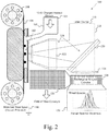
- a device 100 which utilizes Raman scattering as a means to detect aerosol particles, such as biological and non biological, without depending on fluorescence.
- the device 100 may be reagent free, and may provide rapid response. For example, accurate detection of particulates of interest may be performed within a measure of seconds.
- the system 100 is flexible and sensitive, e.g., able to be tuned to detect different particle types.
- the device 100 includes a sampler 102 to collect samples onto a sample substrate for interrogation.
- the illustrative sampler 102 may comprise, for example, a small area electrostatic aerosol collector that collects aerosol particles out of that air by charging particles that enter an air inlet 104. The particles are charged, e.g., using a high voltage power source, and the charged particles are then impacted on an oppositely charged (or neutral charged) impaction substrate 106.
- near 100% collection efficiency may be realized by a small area electrostatic aerosol collector at the illustrative flow rate of 1 L min-1.
- other collection technologies and flow rates may alternatively be implemented.
- the impaction substrate 106 may comprise, for example, an aluminized Mylar® tape.
- the impaction substrate 106 is wound around a metalized tape spool 108, which is configured such that the surface of the impaction substrate 106 that collects the particulates is held at a ground potential 110.
- the impaction substrate 106 e.g., the tape
- the impaction substrate 106 may be in constant motion, e.g., at a speed of tens of ⁇ m per second, so that after impaction the aerosol particles that are collected by the sampler 102 are moved towards an interrogation region 112.
- the impaction substrate 106 may be jogged or otherwise advanced, as the application dictates.
- a detection system 114 is positioned proximate to the interrogation region 112 for evaluating collected particulates.
- the detection system 114 comprises in general, a laser source 116 and an optical system 118 comprising optical devices, e.g., a dichroic mirror 120, an objective 122, and a filter 124.
- the optical system 118 may comprise other and/or additional lenses, filters, mirrors, and other optical devices etc.
- the detection system 114 may comprise the optical imaging system 10 described in greater detail above, with reference to Fig. 1 .
- the collected particles in the interrogation region 112 arc illuminated by the laser source 116 such as a visible laser.
- the laser beam is directed by the dichroic mirror 120 through the objective 122 positioned proximate to the interrogation region 112.
- the interaction between the laser light and the particles leads to Raman scattering of light that is shifted in wavelength from the laser 116.
- Light from the interrogation region 112 is collected, e.g., directed back through the objective 122 of the optical system.
- light from the interrogation region 112 is scattered and dispersed in order to separate the wavelengths of the laser light reflected back into the system using appropriate filter optics 124.
- wavelengths are chosen for monitoring that have been shown to be sufficient to efficiently discriminate biological from non biological particles.
- Optimum wavelength bands may be definable which can be monitored in order to detect agents of interest.
- the device 100 is utilized for rapidly discriminating between biological and non biological particles, such as aerosol particles, using narrow band Raman scattering.
- a typical biological particle Raman spectrum that may be detected by the device 100 is illustrated with reference to Fig. 3 .
- the large peak near 3000 cm -1 Raman shift is due to the presence of carbon hydrogen (CH) bonds within the biological material in the illustrative example.
- simulants as well as chemical aerosols were illuminated within an 80 ⁇ m 2 area or 80 ⁇ m long lines with 30 milliwatts (mW) of 633.2 nm laser light or less.
- mW milliwatts
- the Raman scattered light was filtered through the filter 124, a bandpass filter, (illustrated as the gray region under the curve of Fig. 3 ), so that only CH scattered light was detected an output device 128 (detector), e.g., a cooled charge coupled device (CCD).
- mW milliwatts
- the basic approach described more fully herein may be possibly changed so as to make detection potentially more rapid, sensitive, and/or accurate.
- the specific laser 12, 116 and/or laser wavelength and/or laser power selected for interrogation may be different from that described above.
- multiple types of output devices may be utilized in order to find options that will be sufficiently sensitive and low noise while being less expensive than cooled CCD arrays.
- the optical system 14, 116 may be modified with regard to the optics that collect the scattering from all of the particles in the illuminated field or illumination line and focuses their scattering onto the detector in order to provided the desired sensitivity according to the intended application.
- it may be necessary to accurately detect the target particles by detecting wider spectral bands that could possibly distinguish fluorescence light from Raman scattered light.
- the devices described more fully herein may be able to detect non fluorescent aerosol particles.
- the technology may even have a response time of less than five seconds because only a few seconds may be required to collect the particles on the tape substrate and move the particles into the interrogation region. Moreover, less than one second of interrogation may be sufficient to detect the Raman scattering.
- the technology may be able to detect the presence of a single target particle on the tape or other sample area.
- the system 10, 100 may be able to discriminate the target, and possibly several targets, from background material. Because all potential targets have a unique Raman scattering signature, the various aspects of the present invention may be flexible and adaptable to different targets. Still further, according to various aspects of the present invention, the technology may not require the use of any reagents and may be able to operate continuously.
- biological particles may be discriminated from non biological particles.
- a detector for several different agents. Doing so will require consideration of the optical system to efficiently collect light scattered at several different wavelengths.
Landscapes
- Physics & Mathematics (AREA)
- Chemical & Material Sciences (AREA)
- Spectroscopy & Molecular Physics (AREA)
- Health & Medical Sciences (AREA)
- General Physics & Mathematics (AREA)
- Biochemistry (AREA)
- Analytical Chemistry (AREA)
- General Health & Medical Sciences (AREA)
- Life Sciences & Earth Sciences (AREA)
- Immunology (AREA)
- Pathology (AREA)
- Dispersion Chemistry (AREA)
- Nuclear Medicine, Radiotherapy & Molecular Imaging (AREA)
- Investigating, Analyzing Materials By Fluorescence Or Luminescence (AREA)
- Microscoopes, Condenser (AREA)
Claims (14)
- Biologisches und chemisches mikroskopisches Targeting-System (100) unter Verwendung von schmalbandiger Raman-Streuung, wobei das Targeting-System (100) Folgendes umfasst:ein Detektionssystem (10; 114), das konfiguriert ist, um Partikel zu bewerten, die auf einem Probensubstrat (20; 106) erfasst wurden, wobei das Detektionssystem (10; 114) umfasst:eine Lichtquelle (12; 116), die zum Emittieren eines Laserstrahls (18) konfiguriert ist; undein Abbildungssystem (14; 118), das so konfiguriert ist, dass es den Strahl (18) entlang mindestens eines optischen Weges so lenkt, dass eine Strahldivergenz bewirkt, dass der Laserfleck in Bezug auf eine optische Brennebene des Abbildungssystems (14; 118) in Richtung des Probensubstrats (20; 106) defokussiert wird, und wobei aufgrund der Partikel auf dem Probensubstrat (20; 106), die C-Hx-Molekularbindungen besitzen, wobei x = 1, 2 oder 3, eine Wechselwirkung der einfallenden Photonen des Strahls (18) mit den C-Hx-Molekularbindungen die Wellenlänge der einfallenden Photonen unelastisch verschiebt, wobei die spektrale Verschiebung eine um ungefähr 3000 cm-1 geringere Energie aufweist als die einfallenden Photonen, wobei das Abbildungssystem (14; 118) umfasst:eine Objektivlinse (34; 122), wobei:der Strahl durch die Objektivlinse (34; 122) hindurchgeht, um das Probensubstrat (20; 106) zu beleuchten; undLicht, das ausgehend von dem Probensubstrat (20; 106) erfasst wird, durch die Objektivlinse (34; 122) zurückgeführt wird;eine optische Vorrichtung (32; 120), die so angeordnet ist, dass sie unelastisch gestreute Photonen von elastisch einfallenden Photonen trennt; undmindestens einen Bandpassfilter (46; 124), der angeordnet ist, um die unelastisch gestreuten Photonen zu filtern, und der nur eine schmale Bandbreite von Licht mit ungefähr 3000 cm-1 weniger als die Laserwellenlänge durchlässt; undeine Ausgabevorrichtung (16; 128), die so konfiguriert ist, dass sie die gefilterten unelastisch gestreuten Photonen empfängt und Informationen ausgibt, die zwischen mindestens einem biologischen Partikel von Interesse, das C-Hx besitzt, und nicht-biologischen Partikeln, die auf dem Probensubstrat (20; 106) enthalten sind, unterscheiden, wobei biologische Partikel durch den Benutzer identifiziert werden können, wenn Bedrohungsspektren als Funktion der Raman-Spektraldispersion in der schmalen Bandbreite des Lichts als Ausgabeinformation bereitgestellt werden.
- System nach Anspruch 1, wobei das Abbildungssystem (14; 118) ferner ein Galilei-Teleskop (22, 24), das den Strahl (18) in mindestens einer Dimension aufweitet, und eine Linse (30) umfasst, wobei der Strahl (18) anschließend durch die Linse (30) in mindestens einer Dimension mit einer Brennweite, die gleich dem Abstand zwischen der Linse (30) und einer hinteren Öffnung des Mikroskopobjektivs (34; 122) ist, wieder fokussiert wird, und wobei die Lichtquelle (12; 116) so konfiguriert ist, dass sie einen Probenbereich in mindestens einem 80 µm2 Sichtfeld beleuchtet.
- System nach einem der vorhergehenden Ansprüche, wobei die optische Vorrichtung (32; 120), die unelastisch gestreute Photonen von elastisch einfallenden Photonen trennt, einen dichroitischen 633-nm-Langpassspiegel umfasst, und das mindestens eine Filter (46; 124) ein 633-nm-Langpassfilter und ein 780-nm-Bandpassfilter umfasst, wobei der dichroitische 633 nm-Langpassspiegel und das 633-nm-Langpassfilter so konfiguriert sind, dass sie die Grundwellenlänge des Lasers (18) über den Spektralbereich, der zwischen mindestens 500 nm bis 633 nm liegt, um mindestens eine Größenordnung abschwächen.
- System nach einem der vorherigen Ansprüche, wobei die Lichtquelle (12; 116) so konfiguriert ist, dass sie den Probenbereich in mindestens einer 80 µm langen Linie mit weniger als 35 Milliwatt Laserstrahlung mit einer Wellenlänge zwischen 576 nm und 650 nm beleuchtet.
- System nach einem der vorhergehenden Ansprüche, wobei die Ausgabevorrichtung (16; 128) eine Kamera einer ladungsgekoppelten Vorrichtung umfasst, die so konfiguriert ist, dass sie die räumliche Lage des Materials in der Probenebene, die unelastische C-Hx-Streuungsinformationen reflektiert, angibt, und wobei die unelastischen C-Hx-Streuungsinformationen in Kombination mit räumlichen Informationen des sichtbaren Bildes und/oder räumlichen Fluoreszenzinformationen verwendet werden können, um die Wahrscheinlichkeit zu erhöhen, dass das Material als biologischer oder chemischer Stoff erkannt wird.
- System nach einem der vorhergehenden Ansprüche, wobei das Probensubstrat (20; 106) ein bandbasiertes System umfasst, das eine auf dem Bandsubstrat erfasste Probe kontinuierlich in einen Abfragebereich des Abbildungssystems (14; 118) bewegt.
- Verfahren zum Durchführen eines biologischen und chemischen mikroskopischen Targeting, Folgendes umfassend:Bewerten von Partikeln, die auf einem Probensubstrat (20; 106) erfasst wurden, mittels schmalbandiger Raman-Streuung durch:Richten eines Laserstrahls (18) von einer Lichtquelle (12; 116) entlang mindestens eines optischen Weges eines Abbildungssystems (14; 118), so dass die Strahldivergenz bewirkt, dass der Laserfleck in Bezug auf eine optische Brennebene des Abbildungssystems (14; 118) in Richtung eines Probensubstrats (20; 106) defokussiert wird, und aufgrund der Partikel auf dem Probensubstrat (20); 106), die C-Hx-Molekularbindungen besitzen, wobei x = 1, 2 oder 3 ist, wobei eine Wechselwirkung der einfallenden Photonen des Strahls (18) mit den C-Hx-Molekularbindungen zu einer unelastischen Verschiebung der Wellenlänge der einfallenden Photonen führt, wobei die spektrale Verschiebung eine um ungefähr 3000 cm-1 geringere Energie aufweist als die einfallenden Photonen;Leiten des Strahls (18) durch eine Objektivlinse (34; 122), um das Probensubstrat (20; 106) zu beleuchten;Erfassen von Licht, das vom Probensubstrat (20; 106) ausgeht, das durch das Abbildungssystem (14; 118) zurückreflektiert wird;Trennen unelastisch gestreuter Photonen von elastisch einfallenden Photonen,Filtern der unelastisch gestreuten Photonen durch mindestens ein Bandpassfilter (46; 124), das nur eine schmale Bandbreite von Licht mit ungefähr 3000 cm-1 weniger als die Laserwellenlänge durchlässt; undLeiten der gefilterten, unelastisch gestreuten Photonen zu einer Ausgabevorrichtung (16; 128), um Informationen, die zwischen mindestens einem biologischen Partikel von Interesse, das C-Hx besitzt, von nicht-biologischen Partikeln, die auf dem Probensubstrat (20; 106) enthalten sind, unterscheiden, zu einem Benutzer zu übertragen, wobei biologische Partikel durch den Benutzer identifiziert werden können, wenn Bedrohungsspektren als eine Funktion der Raman-Spektraldispersion in der schmalen Bandbreite des Lichts als Ausgabeinformation bereitgestellt werden.
- Verfahren nach Anspruch 7, wobei das Richten des Laserstrahls (18) von der Lichtquelle (12; 116) auf das Probensubstrat (20; 106) entlang mindestens eines optischen Wegs des Abbildungssystems (14; 118) das Leiten des Strahls durch ein Galilei-Teleskop (22, 24), das den Strahl (18) in mindestens einer Dimension aufweitet, und durch eine Linse (30) umfasst, wobei der Strahl (18) anschließend durch die Linse (30) mit einer Brennweite, die gleich dem Abstand zwischen der Linse (30) und einer hinteren Öffnung des Mikroskopobjektivs (34; 122) ist, in mindestens einer Dimension neu fokussiert wird.
- Verfahren nach Anspruch 7 oder Anspruch 8, wobei das Richten des Laserstrahls (18) von der Lichtquelle (12; 116) auf das Probensubstrat (20; 106) entlang mindestens eines optischen Wegs des Abbildungssystems (14; 118) das Konfigurieren des Laserstrahls (18) umfasst, um den Probenbereich in mindestens einem 80 µm2 Sichtfeld mit mindestens 35 Milliwatt Laserstrahlung mit einer Wellenlänge von weniger als 633 nm zu beleuchten.
- Verfahren nach einem der Ansprüche 7 bis 9, wobei das Trennen unelastisch gestreuter Photonen von elastisch einfallenden Photonen das Verwenden eines Langpassfilters und eines Bandpassfilters 3000 cm-1 weniger als die Laserwellenlänge umfasst, und wobei das Trennen unelastisch gestreuter Photonen von elastisch einfallenden Photonen gegebenenfalls das Verwenden eines dichroitischen Spiegels mit 633 nm (32; 120), eines 633-nm-Langpassfilters und eines 780-nm-Bandpassfilters (46; 124) umfasst, wobei der dichroitische Spiegel (32; 120) und das Langpassfilter die Grundwellenlänge des Lasers (18) um mindestens eine Größenordnung durch den Spektralbereich abschwächen, der zwischen mindestens 500 nm bis 633 nm liegt.
- Verfahren nach einem der Ansprüche 7 bis 10, wobei das Leiten der unelastisch gestreuten Photonen zu der Ausgabevorrichtung (16; 128) das Leiten der unelastisch gestreuten Photonen zu einer Kamera einer ladungsgekoppelten Vorrichtung umfasst, die die räumliche Lage des Materials in der Probenebene, die unelastische C-Hx-Streuungsinformationen reflektiert, angibt.
- Verfahren nach einem der Ansprüche 7 bis 11, ferner umfassend das Verwenden der räumlichen unelastischen C-Hx-Streuungsinformationen in Kombination mit den räumlichen Informationen des sichtbaren Bildes und/oder der räumlichen Fluoreszenzinformationen, um die Wahrscheinlichkeit zu erhöhen, dass das Material als biologischer oder chemischer Stoff erkannt wird.
- Verfahren nach einem der Ansprüche 7 bis 12, ferner umfassend das Verwenden der räumlichen unelastischen C-Hx-Streuungsinformationen in Kombination mit mindestens einem anderen molekularen Bindungstyp, um die Wahrscheinlichkeit zu erhöhen, dass das Material als biologischer oder chemischer Stoff erkannt wird.
- Verfahren nach einem der Ansprüche 7 bis 13, ferner umfassend das Verwenden von mindestens zwei Filtern, um das von dem Probensubstrat (20; 106) ausgehende erfasste Licht zu filtern, wobei zwei Bilder durch die Ausgabevorrichtung (16; 128) erfasst werden, wobei ein Bild unter Verwendung jedes Filters erfasst wird, wobei die Bilder voneinander subtrahiert werden, um den spektral schmalen Bereich des Spektrums aufzudecken, in dem die unelastische C-Hx-Streuung auftritt.
Applications Claiming Priority (2)
| Application Number | Priority Date | Filing Date | Title |
|---|---|---|---|
| US3151708P | 2008-02-26 | 2008-02-26 | |
| PCT/US2009/035316 WO2009108795A1 (en) | 2008-02-26 | 2009-02-26 | Biological and chemical microscopic targeting |
Publications (2)
| Publication Number | Publication Date |
|---|---|
| EP2257789A1 EP2257789A1 (de) | 2010-12-08 |
| EP2257789B1 true EP2257789B1 (de) | 2020-10-28 |
Family
ID=40740181
Family Applications (1)
| Application Number | Title | Priority Date | Filing Date |
|---|---|---|---|
| EP09715017.1A Active EP2257789B1 (de) | 2008-02-26 | 2009-02-26 | Biologisches und chemisches mikroskopisches targeting |
Country Status (4)
| Country | Link |
|---|---|
| US (1) | US8441632B2 (de) |
| EP (1) | EP2257789B1 (de) |
| JP (3) | JP5972531B2 (de) |
| WO (1) | WO2009108795A1 (de) |
Families Citing this family (15)
| Publication number | Priority date | Publication date | Assignee | Title |
|---|---|---|---|---|
| EP2399115B1 (de) | 2009-02-18 | 2016-01-06 | Battelle Memorial Institute | Elektrostatischer aerosolsammler für kleinbereiche |
| WO2011133516A1 (en) | 2010-04-19 | 2011-10-27 | Battelle Memorial Institute | Electrohydrodynamic spraying |
| JP5667809B2 (ja) * | 2010-08-06 | 2015-02-12 | 株式会社四国総合研究所 | 光学式ガスセンサ |
| JP2012217382A (ja) * | 2011-04-08 | 2012-11-12 | Fuji Electric Co Ltd | 微生物検出装置 |
| JP5748687B2 (ja) * | 2012-02-23 | 2015-07-15 | シャープ株式会社 | 粒子検出装置および空調機器 |
| US10724935B2 (en) | 2014-11-07 | 2020-07-28 | Pollen Sense LLC | Automated airborne particulate matter collection, imaging, identification, and analysis |
| CN106053303A (zh) * | 2016-05-18 | 2016-10-26 | 西南技术物理研究所 | 激光前向散射云滴谱探测系统 |
| JP6643970B2 (ja) * | 2016-11-07 | 2020-02-12 | 株式会社日立製作所 | 光学装置、光学測定方法 |
| NL2018855B1 (en) | 2017-05-05 | 2018-11-14 | Illumina Inc | Laser line illuminator for high throughput sequencing |
| EP3814745A4 (de) | 2018-05-04 | 2022-01-19 | Bioscout Pty Ltd | Probenahmevorrichtung für teilchen und analyse |
| CN114585903B (zh) | 2019-09-23 | 2023-08-04 | 泽特奥科技公司 | 快速自主检测气溶胶粒子的系统和方法 |
| US12074018B2 (en) | 2019-09-23 | 2024-08-27 | Zeteo Tech, Inc. | Systems and methods of rapid and autonomous detection of aerosol particles |
| CN110705089B (zh) * | 2019-09-27 | 2021-04-16 | 中国科学院遥感与数字地球研究所 | 一种细模态气溶胶参数反演方法 |
| CN113495043B (zh) * | 2020-03-18 | 2023-11-10 | 江苏长电科技股份有限公司 | 微尺度衍射图像检测装置 |
| KR102442981B1 (ko) * | 2021-03-30 | 2022-09-13 | 이화여자대학교 산학협력단 | 순간 라만 이미징 장치 |
Citations (3)
| Publication number | Priority date | Publication date | Assignee | Title |
|---|---|---|---|---|
| US20020091322A1 (en) * | 1998-12-03 | 2002-07-11 | Joseph Chaiken | Method and apparatus for noninvasive assessment of skin condition and diagnosis of skin abnormalities |
| US20060250613A1 (en) * | 2005-04-14 | 2006-11-09 | Chem Image Corporation | Method and applications to enhance and image optical signals from biological objects |
| WO2007009119A2 (en) * | 2005-07-14 | 2007-01-18 | Battelle Memorial Institute | Systems and methods for biological and chemical detection |
Family Cites Families (20)
| Publication number | Priority date | Publication date | Assignee | Title |
|---|---|---|---|---|
| JPS4874891A (de) * | 1971-12-29 | 1973-10-09 | ||
| US5048959A (en) * | 1990-06-01 | 1991-09-17 | The Regents Of The University Of Michigan | Spectrographic imaging system |
| EP0740133B1 (de) * | 1991-11-16 | 1997-09-10 | RENISHAW plc | Probenbeleuchtung für spektroskopisches Gerät und Verfahren |
| US5822061A (en) * | 1992-01-20 | 1998-10-13 | Dilor | Spectrometry apparatus |
| WO1996010737A1 (en) * | 1994-09-30 | 1996-04-11 | Renishaw Plc | Methods and apparatus for indentation, scratch or tribological testing |
| GB9511490D0 (en) * | 1995-06-07 | 1995-08-02 | Renishaw Plc | Raman microscope |
| JPH09243563A (ja) * | 1996-03-04 | 1997-09-19 | Tokuyama Corp | 有機物の分析方法 |
| US5866430A (en) * | 1996-06-13 | 1999-02-02 | Grow; Ann E. | Raman optrode processes and devices for detection of chemicals and microorganisms |
| JPH1038807A (ja) * | 1996-07-23 | 1998-02-13 | Hamamatsu Photonics Kk | プラスチックの判別方法およびプラスチックの判別装置 |
| US6002476A (en) * | 1998-04-22 | 1999-12-14 | Chemicon Inc. | Chemical imaging system |
| WO1999058740A1 (fr) * | 1998-05-14 | 1999-11-18 | Sony Corporation | Procede et appareil de formation de films minces |
| JP4897945B2 (ja) * | 2000-08-25 | 2012-03-14 | テクノポリマー株式会社 | 樹脂選別装置、樹脂選別システム、及び樹脂選別方法 |
| JP4136301B2 (ja) * | 2000-09-28 | 2008-08-20 | 義宏 田岸 | 放射性イオン検出器 |
| US7057721B2 (en) * | 2002-01-10 | 2006-06-06 | Chemimage Corporation | Wide field method for detecting pathogenic microorganisms |
| JP4058624B2 (ja) * | 2002-11-28 | 2008-03-12 | 株式会社島津製作所 | 大気中の浮遊粒子状物質の捕集・測定装置 |
| DE102004034997A1 (de) * | 2004-07-16 | 2006-02-02 | Carl Zeiss Jena Gmbh | Lichtrastermikroskop mit bewegter Lochscheibe und Verwendung |
| JP2008533448A (ja) * | 2005-02-09 | 2008-08-21 | ケムイメージ コーポレイション | 脅威物質を検出及び識別するシステム及び方法 |
| US7518728B2 (en) * | 2005-09-30 | 2009-04-14 | Intel Corporation | Method and instrument for collecting fourier transform (FT) Raman spectra for imaging applications |
| US7558619B2 (en) * | 2005-10-04 | 2009-07-07 | Nu Skin International, Inc. | Raman instrument for measuring weak signals in the presence of strong background fluorescence |
| US7333190B1 (en) * | 2006-10-26 | 2008-02-19 | Itt Manufacturing Enterprises, Inc. | Raman interrogation of threat aerosols |
-
2009
- 2009-02-26 JP JP2010548871A patent/JP5972531B2/ja active Active
- 2009-02-26 EP EP09715017.1A patent/EP2257789B1/de active Active
- 2009-02-26 WO PCT/US2009/035316 patent/WO2009108795A1/en not_active Ceased
-
2010
- 2010-08-25 US US12/868,553 patent/US8441632B2/en active Active
-
2014
- 2014-10-22 JP JP2014215747A patent/JP2015043098A/ja active Pending
-
2015
- 2015-07-31 JP JP2015152738A patent/JP6096846B2/ja active Active
Patent Citations (3)
| Publication number | Priority date | Publication date | Assignee | Title |
|---|---|---|---|---|
| US20020091322A1 (en) * | 1998-12-03 | 2002-07-11 | Joseph Chaiken | Method and apparatus for noninvasive assessment of skin condition and diagnosis of skin abnormalities |
| US20060250613A1 (en) * | 2005-04-14 | 2006-11-09 | Chem Image Corporation | Method and applications to enhance and image optical signals from biological objects |
| WO2007009119A2 (en) * | 2005-07-14 | 2007-01-18 | Battelle Memorial Institute | Systems and methods for biological and chemical detection |
Also Published As
| Publication number | Publication date |
|---|---|
| EP2257789A1 (de) | 2010-12-08 |
| US8441632B2 (en) | 2013-05-14 |
| WO2009108795A1 (en) | 2009-09-03 |
| JP2015043098A (ja) | 2015-03-05 |
| US20110026018A1 (en) | 2011-02-03 |
| JP5972531B2 (ja) | 2016-08-17 |
| JP2016006427A (ja) | 2016-01-14 |
| JP2011513734A (ja) | 2011-04-28 |
| JP6096846B2 (ja) | 2017-03-15 |
Similar Documents
| Publication | Publication Date | Title |
|---|---|---|
| EP2257789B1 (de) | Biologisches und chemisches mikroskopisches targeting | |
| US8218144B2 (en) | Pathogen and particle detector system and method | |
| JP4598766B2 (ja) | 生物学的微粒子及び非生物学的微粒子を検出し且つ分類するためのマルチスペクトル光学方法及びシステム | |
| US10267734B2 (en) | Wavelength dispersive microscope spectrofluorometer for characterizing multiple particles simultaneously | |
| US7495752B2 (en) | System and method for the deposition, detection and identification of threat agents | |
| US8094294B2 (en) | Multipoint method for identifying hazardous agents | |
| US20080002180A1 (en) | Systems and methods for use in detecting harmful aerosol particles | |
| WO2006083316A2 (en) | Multipoint method for identifying hazardous agents | |
| CN121275568A (zh) | 一种基于激光诱导荧光的气溶胶检测设备 | |
| TR202008361A1 (tr) | Havada ve yüzeylerde bulunan bi̇yo parçaciklarin tespi̇t edi̇lmesi̇ne yöneli̇k si̇stemler | |
| HK1105453B (en) | Pathogen and particle detector system and method |
Legal Events
| Date | Code | Title | Description |
|---|---|---|---|
| PUAI | Public reference made under article 153(3) epc to a published international application that has entered the european phase |
Free format text: ORIGINAL CODE: 0009012 |
|
| 17P | Request for examination filed |
Effective date: 20100924 |
|
| AK | Designated contracting states |
Kind code of ref document: A1 Designated state(s): AT BE BG CH CY CZ DE DK EE ES FI FR GB GR HR HU IE IS IT LI LT LU LV MC MK MT NL NO PL PT RO SE SI SK TR |
|
| AX | Request for extension of the european patent |
Extension state: AL BA RS |
|
| DAX | Request for extension of the european patent (deleted) | ||
| STAA | Information on the status of an ep patent application or granted ep patent |
Free format text: STATUS: EXAMINATION IS IN PROGRESS |
|
| 17Q | First examination report despatched |
Effective date: 20170329 |
|
| GRAP | Despatch of communication of intention to grant a patent |
Free format text: ORIGINAL CODE: EPIDOSNIGR1 |
|
| STAA | Information on the status of an ep patent application or granted ep patent |
Free format text: STATUS: GRANT OF PATENT IS INTENDED |
|
| RIC1 | Information provided on ipc code assigned before grant |
Ipc: G01N 15/14 20060101ALN20191120BHEP Ipc: G01N 15/06 20060101ALI20191120BHEP Ipc: G01N 21/65 20060101AFI20191120BHEP Ipc: G01J 3/44 20060101ALI20191120BHEP |
|
| INTG | Intention to grant announced |
Effective date: 20191213 |
|
| GRAJ | Information related to disapproval of communication of intention to grant by the applicant or resumption of examination proceedings by the epo deleted |
Free format text: ORIGINAL CODE: EPIDOSDIGR1 |
|
| STAA | Information on the status of an ep patent application or granted ep patent |
Free format text: STATUS: EXAMINATION IS IN PROGRESS |
|
| GRAP | Despatch of communication of intention to grant a patent |
Free format text: ORIGINAL CODE: EPIDOSNIGR1 |
|
| STAA | Information on the status of an ep patent application or granted ep patent |
Free format text: STATUS: GRANT OF PATENT IS INTENDED |
|
| INTG | Intention to grant announced |
Effective date: 20200507 |
|
| RIC1 | Information provided on ipc code assigned before grant |
Ipc: G01J 3/44 20060101ALI20200424BHEP Ipc: G01N 15/06 20060101ALI20200424BHEP Ipc: G01N 15/14 20060101ALN20200424BHEP Ipc: G01N 21/65 20060101AFI20200424BHEP |
|
| GRAS | Grant fee paid |
Free format text: ORIGINAL CODE: EPIDOSNIGR3 |
|
| GRAJ | Information related to disapproval of communication of intention to grant by the applicant or resumption of examination proceedings by the epo deleted |
Free format text: ORIGINAL CODE: EPIDOSDIGR1 |
|
| GRAL | Information related to payment of fee for publishing/printing deleted |
Free format text: ORIGINAL CODE: EPIDOSDIGR3 |
|
| STAA | Information on the status of an ep patent application or granted ep patent |
Free format text: STATUS: EXAMINATION IS IN PROGRESS |
|
| GRAR | Information related to intention to grant a patent recorded |
Free format text: ORIGINAL CODE: EPIDOSNIGR71 |
|
| STAA | Information on the status of an ep patent application or granted ep patent |
Free format text: STATUS: GRANT OF PATENT IS INTENDED |
|
| GRAA | (expected) grant |
Free format text: ORIGINAL CODE: 0009210 |
|
| STAA | Information on the status of an ep patent application or granted ep patent |
Free format text: STATUS: THE PATENT HAS BEEN GRANTED |
|
| INTC | Intention to grant announced (deleted) | ||
| RIC1 | Information provided on ipc code assigned before grant |
Ipc: G01N 15/06 20060101ALI20200910BHEP Ipc: G01N 21/65 20060101AFI20200910BHEP Ipc: G01J 3/44 20060101ALI20200910BHEP Ipc: G01N 15/14 20060101ALN20200910BHEP |
|
| INTG | Intention to grant announced |
Effective date: 20200917 |
|
| AK | Designated contracting states |
Kind code of ref document: B1 Designated state(s): AT BE BG CH CY CZ DE DK EE ES FI FR GB GR HR HU IE IS IT LI LT LU LV MC MK MT NL NO PL PT RO SE SI SK TR |
|
| REG | Reference to a national code |
Ref country code: GB Ref legal event code: FG4D |
|
| REG | Reference to a national code |
Ref country code: CH Ref legal event code: EP |
|
| REG | Reference to a national code |
Ref country code: DE Ref legal event code: R096 Ref document number: 602009062975 Country of ref document: DE |
|
| REG | Reference to a national code |
Ref country code: AT Ref legal event code: REF Ref document number: 1328699 Country of ref document: AT Kind code of ref document: T Effective date: 20201115 |
|
| REG | Reference to a national code |
Ref country code: IE Ref legal event code: FG4D |
|
| REG | Reference to a national code |
Ref country code: AT Ref legal event code: MK05 Ref document number: 1328699 Country of ref document: AT Kind code of ref document: T Effective date: 20201028 |
|
| REG | Reference to a national code |
Ref country code: NL Ref legal event code: MP Effective date: 20201028 |
|
| PG25 | Lapsed in a contracting state [announced via postgrant information from national office to epo] |
Ref country code: GR Free format text: LAPSE BECAUSE OF FAILURE TO SUBMIT A TRANSLATION OF THE DESCRIPTION OR TO PAY THE FEE WITHIN THE PRESCRIBED TIME-LIMIT Effective date: 20210129 Ref country code: FI Free format text: LAPSE BECAUSE OF FAILURE TO SUBMIT A TRANSLATION OF THE DESCRIPTION OR TO PAY THE FEE WITHIN THE PRESCRIBED TIME-LIMIT Effective date: 20201028 Ref country code: NL Free format text: LAPSE BECAUSE OF FAILURE TO SUBMIT A TRANSLATION OF THE DESCRIPTION OR TO PAY THE FEE WITHIN THE PRESCRIBED TIME-LIMIT Effective date: 20201028 Ref country code: PT Free format text: LAPSE BECAUSE OF FAILURE TO SUBMIT A TRANSLATION OF THE DESCRIPTION OR TO PAY THE FEE WITHIN THE PRESCRIBED TIME-LIMIT Effective date: 20210301 Ref country code: NO Free format text: LAPSE BECAUSE OF FAILURE TO SUBMIT A TRANSLATION OF THE DESCRIPTION OR TO PAY THE FEE WITHIN THE PRESCRIBED TIME-LIMIT Effective date: 20210128 |
|
| REG | Reference to a national code |
Ref country code: LT Ref legal event code: MG4D |
|
| PG25 | Lapsed in a contracting state [announced via postgrant information from national office to epo] |
Ref country code: SE Free format text: LAPSE BECAUSE OF FAILURE TO SUBMIT A TRANSLATION OF THE DESCRIPTION OR TO PAY THE FEE WITHIN THE PRESCRIBED TIME-LIMIT Effective date: 20201028 Ref country code: PL Free format text: LAPSE BECAUSE OF FAILURE TO SUBMIT A TRANSLATION OF THE DESCRIPTION OR TO PAY THE FEE WITHIN THE PRESCRIBED TIME-LIMIT Effective date: 20201028 Ref country code: LV Free format text: LAPSE BECAUSE OF FAILURE TO SUBMIT A TRANSLATION OF THE DESCRIPTION OR TO PAY THE FEE WITHIN THE PRESCRIBED TIME-LIMIT Effective date: 20201028 Ref country code: BG Free format text: LAPSE BECAUSE OF FAILURE TO SUBMIT A TRANSLATION OF THE DESCRIPTION OR TO PAY THE FEE WITHIN THE PRESCRIBED TIME-LIMIT Effective date: 20210128 Ref country code: AT Free format text: LAPSE BECAUSE OF FAILURE TO SUBMIT A TRANSLATION OF THE DESCRIPTION OR TO PAY THE FEE WITHIN THE PRESCRIBED TIME-LIMIT Effective date: 20201028 Ref country code: ES Free format text: LAPSE BECAUSE OF FAILURE TO SUBMIT A TRANSLATION OF THE DESCRIPTION OR TO PAY THE FEE WITHIN THE PRESCRIBED TIME-LIMIT Effective date: 20201028 Ref country code: IS Free format text: LAPSE BECAUSE OF FAILURE TO SUBMIT A TRANSLATION OF THE DESCRIPTION OR TO PAY THE FEE WITHIN THE PRESCRIBED TIME-LIMIT Effective date: 20210228 |
|
| PG25 | Lapsed in a contracting state [announced via postgrant information from national office to epo] |
Ref country code: HR Free format text: LAPSE BECAUSE OF FAILURE TO SUBMIT A TRANSLATION OF THE DESCRIPTION OR TO PAY THE FEE WITHIN THE PRESCRIBED TIME-LIMIT Effective date: 20201028 |
|
| REG | Reference to a national code |
Ref country code: DE Ref legal event code: R097 Ref document number: 602009062975 Country of ref document: DE |
|
| PG25 | Lapsed in a contracting state [announced via postgrant information from national office to epo] |
Ref country code: LT Free format text: LAPSE BECAUSE OF FAILURE TO SUBMIT A TRANSLATION OF THE DESCRIPTION OR TO PAY THE FEE WITHIN THE PRESCRIBED TIME-LIMIT Effective date: 20201028 Ref country code: RO Free format text: LAPSE BECAUSE OF FAILURE TO SUBMIT A TRANSLATION OF THE DESCRIPTION OR TO PAY THE FEE WITHIN THE PRESCRIBED TIME-LIMIT Effective date: 20201028 Ref country code: SK Free format text: LAPSE BECAUSE OF FAILURE TO SUBMIT A TRANSLATION OF THE DESCRIPTION OR TO PAY THE FEE WITHIN THE PRESCRIBED TIME-LIMIT Effective date: 20201028 Ref country code: EE Free format text: LAPSE BECAUSE OF FAILURE TO SUBMIT A TRANSLATION OF THE DESCRIPTION OR TO PAY THE FEE WITHIN THE PRESCRIBED TIME-LIMIT Effective date: 20201028 Ref country code: CZ Free format text: LAPSE BECAUSE OF FAILURE TO SUBMIT A TRANSLATION OF THE DESCRIPTION OR TO PAY THE FEE WITHIN THE PRESCRIBED TIME-LIMIT Effective date: 20201028 |
|
| PG25 | Lapsed in a contracting state [announced via postgrant information from national office to epo] |
Ref country code: DK Free format text: LAPSE BECAUSE OF FAILURE TO SUBMIT A TRANSLATION OF THE DESCRIPTION OR TO PAY THE FEE WITHIN THE PRESCRIBED TIME-LIMIT Effective date: 20201028 |
|
| PLBE | No opposition filed within time limit |
Free format text: ORIGINAL CODE: 0009261 |
|
| STAA | Information on the status of an ep patent application or granted ep patent |
Free format text: STATUS: NO OPPOSITION FILED WITHIN TIME LIMIT |
|
| PG25 | Lapsed in a contracting state [announced via postgrant information from national office to epo] |
Ref country code: MC Free format text: LAPSE BECAUSE OF FAILURE TO SUBMIT A TRANSLATION OF THE DESCRIPTION OR TO PAY THE FEE WITHIN THE PRESCRIBED TIME-LIMIT Effective date: 20201028 |
|
| 26N | No opposition filed |
Effective date: 20210729 |
|
| REG | Reference to a national code |
Ref country code: BE Ref legal event code: MM Effective date: 20210228 |
|
| PG25 | Lapsed in a contracting state [announced via postgrant information from national office to epo] |
Ref country code: LI Free format text: LAPSE BECAUSE OF NON-PAYMENT OF DUE FEES Effective date: 20210228 Ref country code: LU Free format text: LAPSE BECAUSE OF NON-PAYMENT OF DUE FEES Effective date: 20210226 Ref country code: IT Free format text: LAPSE BECAUSE OF FAILURE TO SUBMIT A TRANSLATION OF THE DESCRIPTION OR TO PAY THE FEE WITHIN THE PRESCRIBED TIME-LIMIT Effective date: 20201028 Ref country code: CH Free format text: LAPSE BECAUSE OF NON-PAYMENT OF DUE FEES Effective date: 20210228 |
|
| PG25 | Lapsed in a contracting state [announced via postgrant information from national office to epo] |
Ref country code: SI Free format text: LAPSE BECAUSE OF FAILURE TO SUBMIT A TRANSLATION OF THE DESCRIPTION OR TO PAY THE FEE WITHIN THE PRESCRIBED TIME-LIMIT Effective date: 20201028 |
|
| PG25 | Lapsed in a contracting state [announced via postgrant information from national office to epo] |
Ref country code: IE Free format text: LAPSE BECAUSE OF NON-PAYMENT OF DUE FEES Effective date: 20210226 |
|
| PG25 | Lapsed in a contracting state [announced via postgrant information from national office to epo] |
Ref country code: IS Free format text: LAPSE BECAUSE OF FAILURE TO SUBMIT A TRANSLATION OF THE DESCRIPTION OR TO PAY THE FEE WITHIN THE PRESCRIBED TIME-LIMIT Effective date: 20210228 |
|
| PG25 | Lapsed in a contracting state [announced via postgrant information from national office to epo] |
Ref country code: BE Free format text: LAPSE BECAUSE OF NON-PAYMENT OF DUE FEES Effective date: 20210228 |
|
| PG25 | Lapsed in a contracting state [announced via postgrant information from national office to epo] |
Ref country code: HU Free format text: LAPSE BECAUSE OF FAILURE TO SUBMIT A TRANSLATION OF THE DESCRIPTION OR TO PAY THE FEE WITHIN THE PRESCRIBED TIME-LIMIT; INVALID AB INITIO Effective date: 20090226 Ref country code: CY Free format text: LAPSE BECAUSE OF FAILURE TO SUBMIT A TRANSLATION OF THE DESCRIPTION OR TO PAY THE FEE WITHIN THE PRESCRIBED TIME-LIMIT Effective date: 20201028 |
|
| PG25 | Lapsed in a contracting state [announced via postgrant information from national office to epo] |
Ref country code: MK Free format text: LAPSE BECAUSE OF FAILURE TO SUBMIT A TRANSLATION OF THE DESCRIPTION OR TO PAY THE FEE WITHIN THE PRESCRIBED TIME-LIMIT Effective date: 20201028 |
|
| PG25 | Lapsed in a contracting state [announced via postgrant information from national office to epo] |
Ref country code: TR Free format text: LAPSE BECAUSE OF FAILURE TO SUBMIT A TRANSLATION OF THE DESCRIPTION OR TO PAY THE FEE WITHIN THE PRESCRIBED TIME-LIMIT Effective date: 20201028 |
|
| PG25 | Lapsed in a contracting state [announced via postgrant information from national office to epo] |
Ref country code: MT Free format text: LAPSE BECAUSE OF FAILURE TO SUBMIT A TRANSLATION OF THE DESCRIPTION OR TO PAY THE FEE WITHIN THE PRESCRIBED TIME-LIMIT Effective date: 20201028 |
|
| PGFP | Annual fee paid to national office [announced via postgrant information from national office to epo] |
Ref country code: GB Payment date: 20260113 Year of fee payment: 18 |
|
| PGFP | Annual fee paid to national office [announced via postgrant information from national office to epo] |
Ref country code: DE Payment date: 20260115 Year of fee payment: 18 |
|
| PGFP | Annual fee paid to national office [announced via postgrant information from national office to epo] |
Ref country code: FR Payment date: 20260109 Year of fee payment: 18 |