EP2258958A2 - Embrayage électromagnétique - Google Patents
Embrayage électromagnétique Download PDFInfo
- Publication number
- EP2258958A2 EP2258958A2 EP10164700A EP10164700A EP2258958A2 EP 2258958 A2 EP2258958 A2 EP 2258958A2 EP 10164700 A EP10164700 A EP 10164700A EP 10164700 A EP10164700 A EP 10164700A EP 2258958 A2 EP2258958 A2 EP 2258958A2
- Authority
- EP
- European Patent Office
- Prior art keywords
- rotating part
- power
- electromagnetic clutch
- electromagnetic
- pulley
- Prior art date
- Legal status (The legal status is an assumption and is not a legal conclusion. Google has not performed a legal analysis and makes no representation as to the accuracy of the status listed.)
- Withdrawn
Links
- 230000005540 biological transmission Effects 0.000 claims abstract description 27
- 230000002093 peripheral effect Effects 0.000 description 8
- 239000003507 refrigerant Substances 0.000 description 7
- 238000006073 displacement reaction Methods 0.000 description 5
- 230000005856 abnormality Effects 0.000 description 4
- 239000012530 fluid Substances 0.000 description 2
- 230000000694 effects Effects 0.000 description 1
- 239000002184 metal Substances 0.000 description 1
- 239000011347 resin Substances 0.000 description 1
- 229920005989 resin Polymers 0.000 description 1
Images

Classifications
-
- F—MECHANICAL ENGINEERING; LIGHTING; HEATING; WEAPONS; BLASTING
- F16—ENGINEERING ELEMENTS AND UNITS; GENERAL MEASURES FOR PRODUCING AND MAINTAINING EFFECTIVE FUNCTIONING OF MACHINES OR INSTALLATIONS; THERMAL INSULATION IN GENERAL
- F16D—COUPLINGS FOR TRANSMITTING ROTATION; CLUTCHES; BRAKES
- F16D27/00—Magnetically- or electrically- actuated clutches; Control or electric circuits therefor
- F16D27/10—Magnetically- or electrically- actuated clutches; Control or electric circuits therefor with an electromagnet not rotating with a clutching member, i.e. without collecting rings
- F16D27/108—Magnetically- or electrically- actuated clutches; Control or electric circuits therefor with an electromagnet not rotating with a clutching member, i.e. without collecting rings with axially movable clutching members
- F16D27/112—Magnetically- or electrically- actuated clutches; Control or electric circuits therefor with an electromagnet not rotating with a clutching member, i.e. without collecting rings with axially movable clutching members with flat friction surfaces, e.g. discs
-
- F—MECHANICAL ENGINEERING; LIGHTING; HEATING; WEAPONS; BLASTING
- F16—ENGINEERING ELEMENTS AND UNITS; GENERAL MEASURES FOR PRODUCING AND MAINTAINING EFFECTIVE FUNCTIONING OF MACHINES OR INSTALLATIONS; THERMAL INSULATION IN GENERAL
- F16D—COUPLINGS FOR TRANSMITTING ROTATION; CLUTCHES; BRAKES
- F16D9/00—Couplings with safety member for disconnecting, e.g. breaking or melting member
- F16D9/02—Couplings with safety member for disconnecting, e.g. breaking or melting member by thermal means, e.g. melting member
-
- F—MECHANICAL ENGINEERING; LIGHTING; HEATING; WEAPONS; BLASTING
- F16—ENGINEERING ELEMENTS AND UNITS; GENERAL MEASURES FOR PRODUCING AND MAINTAINING EFFECTIVE FUNCTIONING OF MACHINES OR INSTALLATIONS; THERMAL INSULATION IN GENERAL
- F16D—COUPLINGS FOR TRANSMITTING ROTATION; CLUTCHES; BRAKES
- F16D9/00—Couplings with safety member for disconnecting, e.g. breaking or melting member
- F16D9/06—Couplings with safety member for disconnecting, e.g. breaking or melting member by breaking due to shear stress
Definitions
- the present invention relates to an electromagnetic clutch which can transmit power from an external drive source to a driven apparatus.
- an electromagnetic clutch having an electromagnetic coil is used for transmitting the power to the driven apparatus.
- the electromagnetic coil of the electromagnetic clutch is energized by electric current supplied from a battery
- a first rotating part provided on the side of the vehicle engine and driven to rotate by the vehicle engine is connected to a second rotating part provided on the side of the compressor and rotatable integrally with the rotary shaft of the compressor.
- the electromagnetic clutch is disengaged thereby to disconnect the first rotating part and the second rotating part from each other.
- the electromagnetic clutch disclosed for example, in the Japanese Patent Application Publication 57-51025 , is operable to be disengaged so as to disconnect the first and the second rotating parts when excessive frictional heat is generated due to the slippage between the first and the second rotating parts.
- a thermal fuse is connected in series to the electromagnetic coil.
- the thermal fuse is disposed on the side of the electromagnetic coil that is adjacent to the friction surfaces of the first rotating part (input rotating part) and the second rotating part (friction plate). If any abnormality, such as deadlock, occur in the compressor and the transmission torque to the compressor is increased excessively, causing slippage between the friction surfaces of the first and the second rotating parts, excessive heat generated on the friction surfaces causes the thermal fuse to be blown out, with the result that the electromagnetic coil is de-energized thereby to disconnect the first and the second rotating parts from each other.
- the present invention is directed to providing an electromagnetic clutch which can release rapidly the connection between a first rotating part provided on the side of a drive source and a second rotating part provided on the side of a rotary shaft of any driven apparatus in the event of any abnormality causing excessive transmission torque to the driven apparatus.
- an electromagnetic clutch is provided on a power transmission path between an external drive source and a driven apparatus.
- the electromagnetic clutch includes a first rotating part, a second rotating part and an electromagnetic coil.
- the first rotating part is disposed in the power transmission path and driven to rotate by power from the external drive source.
- the second rotating part is disposed in the power transmission path and mounted on a rotary shaft of the driven apparatus for rotation with the rotary shaft of the driven apparatus.
- the electromagnetic coil is energized by electric current supplied from a power source to generate electromagnetic attraction force by which the first rotating part and the second rotating part are connected to each other for transmitting power between the first rotating part and the second rotating part.
- a power cutoff mechanism is disposed in the power transmission path for stopping excessive power transmission from the external drive source to the driven apparatus when the electromagnetic coil is energized.
- the compressor 10 includes a cylinder block 11, a front housing 12 and a rear housing 14.
- the front housing 12 is fixedly connected to the front end of the cylinder block 11, and the rear housing 14 is fixedly connected to the rear end of the cylinder block 11 through a valve plate assembly 13.
- the cylinder block 11 and the front housing 12 define a crank chamber 15 therebetween.
- a rotary shaft 16 is rotatably supported by the front housing 12 and the cylinder block 11 at the center thereof.
- a rotary shaft 16 is rotatably supported by the front housing 12 at the front thereof through a roller bearing 17 and by the cylinder block 11 at the rear thereof through a roller bearing 18.
- the front end of the rotary shaft 16 extends outside the front housing 12 and is connected to a vehicle engine E through an electromagnetic clutch 30.
- a lug plate 19 is fixedly mounted on the rotary shaft 16 on the rear side of the roller bearing 17 for rotation with the rotary shaft 16.
- a swash plate 20 is mounted on the rotary shaft 16 on the rear side of the lug plate 19 so as to be inclinable with respect to the rotary shaft 16 and slidable in the axial direction of the rotary shaft 16.
- the swash plate 20 has a connecting portion 20A extending therefrom and having at the distal end thereof a guide pins 21.
- the guide pin 21 is engaged with a guide hole 19A formed in the lug plate 19.
- the swash plate 20 is rotatable integrally with the lug plate 19.
- a plurality of cylinder bores 24 is formed through the cylinder block 11 around the rotary shaft 16.
- Pistons 22 are received reciprocably movably in the respective cylinder bores 24 and connected to the swash plate 20 through shoes 23. As the swash plate 20 rotates with rotation of the rotary shaft 16, the pistons 22 are reciprocated in the respective cylinder bores 24.
- a discharge chamber 14A is formed in the rear housing 14 at the center thereof and connected to an external refrigerant circuit through an outlet (not shown).
- An annular cylindrical suction chamber 14B is formed in the outer periphery of the rear housing 14 and connected to the external refrigerant circuit through an inlet (not shown).
- Suction ports 13B, suction valves 13C, discharge ports 13A and discharge valves 13D are formed in the valve plate assembly 13.
- Each cylinder bore 24 is communicable with the suction chamber 14B through the suction port 13B and the suction valve 13C and the discharge chamber 14A through the discharge port 13A and the discharge valve 13D.
- Refrigerant gas is drawn from the suction chamber 14B into the cylinder bore 24 by reciprocating motion of the piston 22 together with rotation of the rotary shaft 16, and the refrigerant gas is compressed and then discharged into the discharge chamber 14A.
- a bleed passage 25 is formed through the cylinder block 11 to provide fluid communication between the crank chamber 15 and the suction chamber 14B.
- a supply passage 26 is formed through the cylinder block 11 and a rear housing 14 to provide fluid communication between the discharge chamber 14A and the crank chamber 15.
- a displacement control valve 27 is disposed in the supply passage 26 for controlling flow rate of high-pressured refrigerant gas flowing from the discharge chamber 14A into the crank chamber 15 through the supply passage 26.
- the pressure of the crank chamber 15 is changed depending on the relation between such flow rate of refrigerant gas flowing through the supply passage 26 and the flow rate of refrigerant gas flowing from the crank chamber 15 into the suction chamber 14B through the bleed passage 25. Therefore, the pressure difference between the crank chamber 15 and the cylinder bore 24 through the piston 22 is changed, so that the inclination angle of the swash plate 20 is changed thereby to adjust the displacement of the compressor.
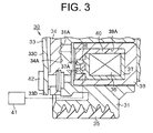
- a pulley 31 serving as a first rotating part on the side of the drive source is rotatably supported through an angular bearing 32 by a boss 12B forming the front projection end of the front housing 12.
- the pulley 31 is connected to the vehicle engine E through a belt 35 which is wound around the pulley 31.
- a hub 33 is fixed to the front end of the rotary shaft 16 extending out of the front housing 12.
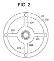
- the hub 33 includes an inner cylindrical portion 33B for transmitting power to the rotary shaft 16 and serving as an inner portion, a plurality of limiter portions 33C serving as a power cutoff mechanism, or four limiter portions 33C in the present embodiment and an outer ring portion 33D for receiving power from the hub 33.
- a hole is formed in the inner cylindrical portion 33B, and the front end portion of the rotary shaft 16 is inserted therein.
- the outer ring portion 33D is formed integrally with the inner cylindrical portion 33B through the limiter portions 33C serving as a power cutoff mechanism.
- the limiter portions 33C are formed in the hub 33, or the hub 33 includes the limiter portion 33C.
- the limiter portions 33C is radially disposed between the inner cylindrical portion 33B and the outer ring portion 33D for transmitting power between the inner cylindrical portion 33B and the outer ring portion 33D.
- the limiter portions 33C are made of a leaf spring, in this preferred embodiment, the hub 33 having the inner cylindrical portion 33B, the limiter portions 33C and the outer ring portion 33D which are integrally formed is made of a sintered metal.
- an armature 34 is connected by connecting pins 42 to the outer ring portion 33D of the hub 33 for rotation therewith.
- the hub 33 and the armature 34 are mounted on the rotary shaft 16 of the compressor 10 for rotation therewith and form a second rotating part provided on the side of the rotary shaft 16.
- An electromagnetic coil 36 is provided in the pulley 31 so that it is positioned on the outer peripheral side of the boss 12B of the front housing 12. The electromagnetic coil 36 is accommodated in a cylindrical coil container 37.
- the coil container 37 is formed on the front side thereof with a fuse holder 37A for holding a thermal fuse 38.
- a cylindrical support member 39 having a coil groove 39A formed therein is supported by the front housing 12.
- the coil container 37 having therein the electromagnetic coil 36 is fitted in the coil groove 39A and fixed thereto by using a resin mold 40.
- the thermal fuse 38 is formed integrally with the electromagnetic coil 36.
- the fuse holder 37A is located on the side of the coil container 37 that is adjacent to the armature 34.
- the thermal fuse 38 is disposed adjacent to the armature 34.
- the thermal fuse 38 is connected to an electrical circuit between the electromagnetic coil 36 and a battery 41 serving as a power source.
- the pulley 31 has a front surface 31A
- the armature 34 has a rear surface 34A, which is normally placed away from the front surface 31 A of the pulley 31.
- the electromagnetic coil 36 When the electromagnetic coil 36 is energized, the rear surface 34A of the armature 34 is moved against the urging force of limiter portions 33C serving as a leaf spring to be pressed against the front surface 31A of the pulley 31 by electromagnetic attraction, so that the pulley 31 and the armature 34 are connected to each other.
- the limiter portion 33C is deformed, so that the armature 34 is moved to connect the pulley 33.
- the power transmission from the vehicle engine E to the rotary shaft 16 is continued while the torque applied at the friction surfaces of the pulley 31 and the armature 34 (or the front surface 31 A of the pulley 31 and the rear surface 34A of the armature 34) is normal or within such a range of magnitude that gives no bad influence on the vehicle engine E.
- the limiter portion 33C of the hub 33 is broken when the limiter portion 33C is subjected to an excessive torque, and used for stopping excessive power transmission from the vehicle engine E to the compressor 10 when the electromagnetic coil 36 is energized.
- the limiter breaking torque is set smaller than the torque at which the belt 35 is slipped on the outer surface of the pulley 31.
- the magnitude of the torque applied at the friction surfaces of the pulley 31 and the armature 34 varies depending on the energizing condition of the electromagnetic coil 36 by the battery 41 and also the condition of the friction surfaces of the pulley 31 and the armature 34, so that the torque at the friction surfaces becomes smaller than the aforementioned limiter breaking torque.
- the limiter portions 33C may not be broken even in the event of a deadlock of the compressor 10 because the limiter portion 33C is subjected to the torque that is smaller than the limiter breaking torque.
- connection between the pulley 31 and the armature 34 is insufficient and the pulley 31 is slipped on the armature 34.
- heat is generated at the friction surfaces of the pulley 31 and the armature 34.
- the thermal fuse 38 disposed adjacent to the armature 34 is blown out by the heat transmitted from the friction surfaces and, therefore, the electrical connection between the electromagnetic coil 36 and the battery 41 is broken, so that the energization of the electromagnetic coil 36 by the battery 41 is stopped. Therefore, the connection between the pulley 31 and the armature 34 is released thereby to stop the power transmission from the pulley 31 to the rotary shaft 16.
- the limiter portion 33C is formed integrally with the hub 33 as a power cutoff mechanism, and the hub 33 itself is breakable.
- the hub 33 may have a limiter member formed separately from the hub 33 itself.
- a pin as a limiter member is inserted through a hole formed in the hub 33 and the pulley 31 in axial direction of the rotary shaft 16 for transmitting power between the hub 33 and the pulley 31.
- the pulley 31 and the hub 33 are connected to each other through the limiter member for transmitting power between the pulley 31 and the hub 33.
- the pin When the pin is subjected to an excessive torque, the pin may be broken to release the connection between the hub 33 and the pulley 31.
- the preferred embodiment may be modified, for example, in such a way that a pulley is disposed so as to cover the outer peripheral surface of the hub 33.
- a limiter member formed separately from the hub 33 itself is made of a rubber member.
- the inner peripheral surface of the pulley 31 and the outer peripheral surface of the hub 33 have a recess.
- the inner peripheral surface of the pulley 31 is faced to the outer peripheral surface of the hub 33.
- the rubber member is disposed between the inner peripheral surface of the pulley 31 and the outer peripheral surface of the hub 33 and has a projection for fitting into the recesses of the pulley 31 and the hub 33. The projection of the rubber member is released from the recesses of the pulley 31 or the hub 33 when the rubber member is subjected to an excessive torque.
- the thermal fuse 38 is disposed on the side of the electromagnetic coil 36 that is adjacent to the armature 34.
- the thermal fuse 38 may be disposed at any position where the heat generated on the friction surfaces of the pulley 31 and the armature 34 may be conducted to the thermal fuse 38.
- the thermal fuse 38 of the electromagnetic clutch 30 may be omitted.
- the rotating part on the side of the drive source is not limited to the pulley 31.
- the rotating part on the side of the drive source may be a sprocket wheel or a gear.
- the present invention is applied to the electromagnetic clutch 30 in the swash plate type variable displacement compressor 10.
- the present invention may be applied to an electromagnetic clutch used in a rotary type compressor, such as a scroll type compressor.
- the present invention is applied to the electromagnetic clutch 30 used in the compressor 10 serving as an apparatus driven by power from the vehicle engine E.
- the present invention is applicable to an electromagnetic clutch used in any auxiliary device of vehicle, such as a mechanical supercharger driven by power from the vehicle engine E.
- An electromagnetic clutch includes an external drive source, a driven apparatus having a rotary shaft, a power transmission path, first and second rotating parts, a power source, an electromagnetic coil and a power cutoff mechanism.
- a power transmission path is formed between the external drive source and the driven apparatus, and in which the first and the second rotating parts, the electromagnetic coil and the power cutoff mechanism are disposed.
- the first rotating part is driven to rotate by power from the external drive source.
- the second rotating part is mounted on the rotary shaft for rotation therewith.
- the electromagnetic coil is energized by electric current from the power source to generate electromagnetic attraction force by which the first and the second rotating parts are connected for transmitting power therebetween.
- the power cutoff mechanism stops excessive power transmission from the external drive source to the driven apparatus when the electromagnetic coil is energized.
Landscapes
- Engineering & Computer Science (AREA)
- General Engineering & Computer Science (AREA)
- Mechanical Engineering (AREA)
- Physics & Mathematics (AREA)
- Electromagnetism (AREA)
- Compressors, Vaccum Pumps And Other Relevant Systems (AREA)
Applications Claiming Priority (1)
| Application Number | Priority Date | Filing Date | Title |
|---|---|---|---|
| JP2009135427A JP2010281392A (ja) | 2009-06-04 | 2009-06-04 | 電磁クラッチ |
Publications (1)
| Publication Number | Publication Date |
|---|---|
| EP2258958A2 true EP2258958A2 (fr) | 2010-12-08 |
Family
ID=42727640
Family Applications (1)
| Application Number | Title | Priority Date | Filing Date |
|---|---|---|---|
| EP10164700A Withdrawn EP2258958A2 (fr) | 2009-06-04 | 2010-06-02 | Embrayage électromagnétique |
Country Status (5)
| Country | Link |
|---|---|
| US (1) | US20100307884A1 (fr) |
| EP (1) | EP2258958A2 (fr) |
| JP (1) | JP2010281392A (fr) |
| KR (1) | KR101205678B1 (fr) |
| CN (1) | CN101907137A (fr) |
Cited By (1)
| Publication number | Priority date | Publication date | Assignee | Title |
|---|---|---|---|---|
| EP2985484A3 (fr) * | 2014-08-08 | 2016-08-17 | Valeo Japan Co., Ltd. | Embrayage électromagnétique |
Families Citing this family (7)
| Publication number | Priority date | Publication date | Assignee | Title |
|---|---|---|---|---|
| JP6229507B2 (ja) * | 2013-01-23 | 2017-11-15 | 株式会社デンソー | 電磁クラッチおよびその製造方法 |
| JP6277781B2 (ja) * | 2014-02-28 | 2018-02-14 | 株式会社デンソー | 電磁クラッチおよびその電磁クラッチの製造方法 |
| JP6332000B2 (ja) * | 2014-12-05 | 2018-05-30 | 株式会社デンソー | 電磁クラッチ |
| CN105736598B (zh) * | 2016-01-11 | 2018-03-13 | 深圳市艾莱茵科技有限公司 | 一种新型电磁离合器 |
| US11009085B2 (en) | 2019-05-17 | 2021-05-18 | Rolls-Royce Corporation | Electromagnetic clutch for gas turbine accessories |
| CN111219428B (zh) * | 2020-03-10 | 2021-05-14 | 厦门南洋职业学院 | 一种基于机电一体化自锁系统的机械刹车装置 |
| US11466735B2 (en) | 2020-03-13 | 2022-10-11 | Rolls-Royce Corporation | Electromagnetic clutch system |
Citations (1)
| Publication number | Priority date | Publication date | Assignee | Title |
|---|---|---|---|---|
| JPS5751025A (en) | 1980-09-10 | 1982-03-25 | Hitachi Ltd | Fitting part for temperature fuse of magnetic clutch |
Family Cites Families (18)
| Publication number | Priority date | Publication date | Assignee | Title |
|---|---|---|---|---|
| KR940001991B1 (ko) * | 1986-02-03 | 1994-03-12 | 산덴 가부시기가이샤 | 전자기 클러치 |
| JP3476164B2 (ja) * | 1995-04-18 | 2003-12-10 | 株式会社豊田自動織機 | 圧縮機における動力伝達構造 |
| JPH1047383A (ja) * | 1996-08-06 | 1998-02-17 | Ogura Clutch Co Ltd | 電磁クラッチ |
| JP3837786B2 (ja) * | 1996-09-12 | 2006-10-25 | 株式会社デンソー | 電磁クラッチ |
| JP3396145B2 (ja) * | 1996-12-16 | 2003-04-14 | 小倉クラッチ株式会社 | 電磁連結装置 |
| JP3941242B2 (ja) * | 1998-07-07 | 2007-07-04 | 株式会社デンソー | 電磁クラッチ |
| JP4174896B2 (ja) * | 1998-09-22 | 2008-11-05 | 株式会社デンソー | 電磁クラッチ |
| JP2003013995A (ja) * | 2001-06-28 | 2003-01-15 | Toyota Industries Corp | 動力伝達機構および圧縮機 |
| JP2003106253A (ja) * | 2001-09-27 | 2003-04-09 | Toyota Industries Corp | 圧縮機 |
| KR100885619B1 (ko) * | 2002-11-14 | 2009-02-24 | 한라공조주식회사 | 파단부를 구비한 클러치리스 압축기 |
| JP3985705B2 (ja) * | 2003-03-24 | 2007-10-03 | 株式会社デンソー | 電磁クラッチ |
| CN2731168Y (zh) * | 2004-06-01 | 2005-10-05 | 北京第一机床电器厂有限公司 | 扭簧电磁离合器 |
| DE102004057848A1 (de) * | 2004-12-01 | 2006-06-08 | Zf Friedrichshafen Ag | Einstellbare Hysteresekupplung |
| JP2006200570A (ja) * | 2005-01-18 | 2006-08-03 | Sanden Corp | 電磁クラッチ |
| KR100652246B1 (ko) * | 2005-07-20 | 2006-12-01 | 우리산업 주식회사 | 자동차 컴프레서에 결합되는 마그네틱 클러치용 필드코일어셈블리의 전원 연결부 |
| JP2007139032A (ja) * | 2005-11-16 | 2007-06-07 | Ogura Clutch Co Ltd | 電磁連結装置 |
| JP4752664B2 (ja) * | 2006-08-04 | 2011-08-17 | 株式会社豊田自動織機 | 動力伝達機構 |
| CN201047409Y (zh) * | 2007-05-21 | 2008-04-16 | 王清刚 | 快速电磁离合器 |
-
2009
- 2009-06-04 JP JP2009135427A patent/JP2010281392A/ja active Pending
-
2010
- 2010-05-07 KR KR1020100043019A patent/KR101205678B1/ko not_active Expired - Fee Related
- 2010-06-02 US US12/792,189 patent/US20100307884A1/en not_active Abandoned
- 2010-06-02 EP EP10164700A patent/EP2258958A2/fr not_active Withdrawn
- 2010-06-03 CN CN2010102337740A patent/CN101907137A/zh active Pending
Patent Citations (1)
| Publication number | Priority date | Publication date | Assignee | Title |
|---|---|---|---|---|
| JPS5751025A (en) | 1980-09-10 | 1982-03-25 | Hitachi Ltd | Fitting part for temperature fuse of magnetic clutch |
Cited By (1)
| Publication number | Priority date | Publication date | Assignee | Title |
|---|---|---|---|---|
| EP2985484A3 (fr) * | 2014-08-08 | 2016-08-17 | Valeo Japan Co., Ltd. | Embrayage électromagnétique |
Also Published As
| Publication number | Publication date |
|---|---|
| KR20100130945A (ko) | 2010-12-14 |
| JP2010281392A (ja) | 2010-12-16 |
| CN101907137A (zh) | 2010-12-08 |
| US20100307884A1 (en) | 2010-12-09 |
| KR101205678B1 (ko) | 2012-11-27 |
Similar Documents
| Publication | Publication Date | Title |
|---|---|---|
| US20100307884A1 (en) | Electromagnetic clutch | |
| CN108223219B (zh) | 用于泵的辅助传动系统 | |
| EP0702167A1 (fr) | Dispositif de transmission de puissance rotative | |
| KR20130089636A (ko) | 부속품을 선택적으로 구동하기 위한 클러치 | |
| CN102200048B (zh) | 车用水泵 | |
| US9062666B2 (en) | Swash plate type variable displacement compressor and method of controlling solenoid thereof | |
| CN103459854A (zh) | 使在驱动轴中一起旋转的调整装置限定地纵向移动的装置和方法 | |
| CN100366938C (zh) | 车辆和用于这种车辆的压缩机的电磁离合器 | |
| JP2003166467A (ja) | 車両用回転機械 | |
| WO2001073307A1 (fr) | Mecanisme de transmission de puissance | |
| EP0867631A1 (fr) | Limiteur de couple | |
| US9027727B2 (en) | Coupling system and method for a vehicle | |
| US6821094B2 (en) | Hybrid power transmission system having first and second clutch mechanisms | |
| JP5445178B2 (ja) | 電磁クラッチ | |
| JP2000170870A (ja) | 動力伝達機構 | |
| JP5397246B2 (ja) | 電磁クラッチ | |
| US6663521B2 (en) | Power transmitting mechanism | |
| WO2018230484A1 (fr) | Dispositif de commande pour embrayage électromagnétique de machine de compression de gaz | |
| JP2007513287A (ja) | 冷却システム | |
| KR20210015165A (ko) | 클러치 및 이를 포함하는 압축기 | |
| JP2020106110A (ja) | 動力伝達機構のトルクリミッタ構造および車載空調用圧縮機 | |
| KR20240050689A (ko) | 압축기 및 이에 포함되는 풀리 제조 방법 | |
| JP2006077954A (ja) | 電磁クラッチ | |
| KR101873755B1 (ko) | 압축기용 압력 조절 밸브 장치 | |
| US20110182757A1 (en) | Apparatus for a pump, and a water pump |
Legal Events
| Date | Code | Title | Description |
|---|---|---|---|
| PUAI | Public reference made under article 153(3) epc to a published international application that has entered the european phase |
Free format text: ORIGINAL CODE: 0009012 |
|
| 17P | Request for examination filed |
Effective date: 20100602 |
|
| AK | Designated contracting states |
Kind code of ref document: A2 Designated state(s): AL AT BE BG CH CY CZ DE DK EE ES FI FR GB GR HR HU IE IS IT LI LT LU LV MC MK MT NL NO PL PT RO SE SI SK SM TR |
|
| AX | Request for extension of the european patent |
Extension state: BA ME RS |
|
| STAA | Information on the status of an ep patent application or granted ep patent |
Free format text: STATUS: THE APPLICATION HAS BEEN WITHDRAWN |
|
| 18W | Application withdrawn |
Effective date: 20130503 |