EP2259280A2 - Interrupteur à combinaison - Google Patents
Interrupteur à combinaison Download PDFInfo
- Publication number
- EP2259280A2 EP2259280A2 EP10005264A EP10005264A EP2259280A2 EP 2259280 A2 EP2259280 A2 EP 2259280A2 EP 10005264 A EP10005264 A EP 10005264A EP 10005264 A EP10005264 A EP 10005264A EP 2259280 A2 EP2259280 A2 EP 2259280A2
- Authority
- EP
- European Patent Office
- Prior art keywords
- contact
- pair
- rotational direction
- contacts
- brush unit
- Prior art date
- Legal status (The legal status is an assumption and is not a legal conclusion. Google has not performed a legal analysis and makes no representation as to the accuracy of the status listed.)
- Granted
Links
Images


Classifications
-
- H—ELECTRICITY
- H01—ELECTRIC ELEMENTS
- H01H—ELECTRIC SWITCHES; RELAYS; SELECTORS; EMERGENCY PROTECTIVE DEVICES
- H01H89/00—Combinations of two or more different basic types of electric switches, relays, selectors and emergency protective devices, not covered by any single one of the other main groups of this subclass
-
- H—ELECTRICITY
- H01—ELECTRIC ELEMENTS
- H01H—ELECTRIC SWITCHES; RELAYS; SELECTORS; EMERGENCY PROTECTIVE DEVICES
- H01H13/00—Switches having rectilinearly-movable operating part or parts adapted for pushing or pulling in one direction only, e.g. push-button switch
- H01H13/50—Switches having rectilinearly-movable operating part or parts adapted for pushing or pulling in one direction only, e.g. push-button switch having a single operating member
- H01H13/64—Switches having rectilinearly-movable operating part or parts adapted for pushing or pulling in one direction only, e.g. push-button switch having a single operating member wherein the switch has more than two electrically distinguishable positions, e.g. multi-position push-button switches
-
- H—ELECTRICITY
- H01—ELECTRIC ELEMENTS
- H01H—ELECTRIC SWITCHES; RELAYS; SELECTORS; EMERGENCY PROTECTIVE DEVICES
- H01H19/00—Switches operated by an operating part which is rotatable about a longitudinal axis thereof and which is acted upon directly by a solid body external to the switch, e.g. by a hand
- H01H19/001—Thumb wheel switches
- H01H19/003—Thumb wheel switches having a pushbutton actuator
Definitions
- the present invention relates to a combination switch including a push switch section having a contact plate elastically deformable with a pressing operation and a contacted point that enters into an electrically conductive state upon contact with the contact plate, the push switch section being configured to detect the pressing operation, and a rotary switch section having a brush unit comprised of a rotary conductive member rotatable about an axis with a lever operation and a plurality of contact shoes formed on the rotary conductive member and a plurality of fixed contacts electrically conductive with the plurality of contact shoes, the rotary switch section being configured to detect a rotary operation.
- a combination switch having the above-described construction is disclosed in Japanese Patent Application " Kokai” No. 2008-177098 .
- This combination switch includes a lower main body and an upper frame.
- the push switch section is disposed at a position exposed through a hole defined at the center of the frame.
- the combination switch further includes a lever protruding laterally from between the main body and the frame.
- At the center of the top face of the main body there are provided a plurality of fixed contacts for the push switch section, and at a position upwardly of the fixed contacts, there is provided an electrode plate that is elastically deformable with a pressing force to render a fixed electrode conductive.
- the plurality of fixed contacts for the rotary switch section.
- a ring-shaped bush having a plurality of contact shoes contactable with the fixed contacts and this bush is operably coupled with a lever.
- the fixed contacts for the rotary switch in particular, there are provided one common contact and two fixed contacts for the detecting of the clockwise rotation and for the counter-clockwise rotation, respectively.
- the brush includes four contact shoes for the ring-shaped fixed portion, these four contact shoes corresponding to the two individual contacts for the detection of the clockwise rotation and the two individual contacts for the detection of the counter-clockwise rotation.
- the plurality of fixed contacts i.e. the individual contacts and the common contact
- the plurality of fixed contacts are arranged over a large cylindrical area relative to the rotational center.
- the distance between adjacent fixed contacts (the peripheral distance relative to the center) needs to be set at a relatively large value.
- the fixed contacts are disposed in distribution over the large cylindrical area, thus making it difficult to form the combination switch compact.
- the object of the present invention is to form compact the combination switch capable of detecting a pressing operation and capable of detecting also a rotational operation in two directions, one in a predetermined direction, the other in the direction opposite thereto.
- a combination switch including a push switch section having a contact plate elastically deformable with a pressing operation and a contacted point that enters into an electrically conductive state upon contact with the contact plate, the push switch section being configured to detect the pressing operation, and a rotary switch section having a brush unit comprised of a rotary conductive member rotatable about an axis with a lever operation and a plurality of contact shoes formed on the rotary conductive member and a plurality of fixed contacts electrically conductive with the plurality of contact shoes, the rotary switch section being configured to detect a rotary operation; wherein said contact shoes of the brush unit include a pair of main contact shoes formed adjacent on a same circle about said axis and a single auxiliary contact shoe; wherein said fixed contacts include a main contact with which said pair of main contact shoes come into contact simultaneously when said brush unit is set under a neutral posture, a pair of first contacts spaced apart from each other across said auxiliary contact shoe in the rotational
- the fixed contacts there are provided five contacts in total, i.e. the single main contact, the one pair of first contacts and the one pair of second contacts.
- the contact shoes of the brush unit there are provided three contact shoes in total, i.e. the one pair of main contact shoes and the single auxiliary contact shoe. That is, the construction requires only three contact shoes. So, there is no need to dispose the contacts associated therewith in distribution over a large area in the same perimeter about the rotational axis. Hence, detection of rotational operation is possible with reduction in the disposing space for the fixed contacts. As a result, it has become possible to form compact the combination switch capable of detecting a pressing operation and capable of detecting also a rotational operation in two directions, one being in a predetermined direction, the other being in the direction opposite thereto.
- the one pair of main contact shoes and the single auxiliary contact shoe are provided in one area of the brush unit relative to the axis and the lever is provided in the other area of the brush unit relative to the same. This arrangement allows for even more compact formation of the combination switch.
- a switch main body for supporting the fixed contacts, and said switch main body includes an open portion where said lever is disposed and three straight lateral walls from which there protrude a lead terminal in electric conduction with said main contact, lead terminals in electric conduction with said one pair of first contacts and lead terminals in electric conduction with said one pair of second contacts.
- the lead terminals in electric conduction with the total five contacts, i.e. the single main contact, the one pair of first contacts and the one pair of second contacts, as the fixed contacts in an area different from the area where the lever projects. From this point of view, according to the above-described arrangement, the total five contacts, i.e. the single main contact, the one pair of first contacts and the one pair of second contacts, can be arranged on the opposite side to the area where the lever projects. So, this arrangement allows for reasonable designing.
- a combination switch includes, within a case C, a push switch section P and a rotary switch section R.
- the push switch section P is capable of detecting a pressing operation in two steps.
- the rotary switch section R is capable of detecting, relative to a neutral posture N, two steps of rotary operations rotated counter-clockwise (an example of "first rotational direction" in the present invention) about an axis X, i.e.
- This combination switch can be provided e.g. at a shutter button portion of a digital camera.
- a zooming lens in response to one step amount of rotary operation of the rotary switch section R from the neutral posture N, a zooming lens is operated to the telephoto side.
- the lens operation to the telephoto side is effected at a high speed.
- the zooming lens in response to one step operation thereof in the opposite direction from the neutral posture N, the zooming lens is operated to the wide-angle side.
- the lens operation to the wide-angle side is effected at a high speed.
- a transition operation to the stand-by condition for a photography such as a focusing operation or an exposure setting operation.
- an operation for starting photographing such as a shutter operation in the still photography mode or a video shooting operation in the movie mode.
- the camera in response to one step rotary operation to one side from the neutral posture N, the camera is activated (power-ON). In response to a rotary operation further to the second step, the still photography mode is selected. And, in response to one step of rotary operation to the other side from the neutral posture N, the camera is activated (power-ON), and in response to a rotary operation further to the second step, the movie mode is selected.
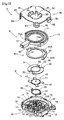
- this combination switch includes a switch main body 10 formed of a resin of an insulating material, a lower switch plate 30 (an example of "contact plate") formed of a conductive material, an upper switch plate 40 formed of a conductive material, a flexibly deformable protective sheet 50, a brush unit 60 in the form of a ring formed of conductive material, a rotor 70 with a lever 72 integrally formed therewith, and a cover 80 formed of a metal plate or a resin plate.
- the switch main body 10 and the cover 80 together constitute the case C of the combination switch.
- the combination switch of the invention is not limited to the use under the posture illustrated in Fig. 1 , in the following discussion, the switch main body 10 will be designated as the lower side and the cover 80 will be designated to as the upper side, respectively, as shown.
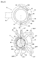
- the switch main body 10 is an integral assembly comprised of a bottom wall portion 11 having a plurality of fixed contacts 20, an outer wall portion 12 projecting upward from the outer peripheral portion of the bottom wall portion 11, a pair of rib-like portions 13 supporting the brush unit 60 from its underside, and a pair of retaining projections 14 engageable with the protective sheet 50 mentioned above.
- the outer wall portion 12 is formed like a wall projecting upward from the bottom wall portion 11, and at a portion of this outer wall portion 12 in its plane view, there is formed an open portion W where a lever 72 is disposed.
- the outer wall portion 12 a portion thereof adjacent the open portion W and a further portion thereof opposed to the open portion W across the axis, straight lateral walls 15 are formed. Further, at the open portion W, there is formed an arcuate guide wall 16 formed about the axis X as its center. And, at opposed ends of this guide wall 16, there are formed a pair of inclined walls 17 inclined relative to the corresponding lateral walls 15 as seen in the plane view.
- the outer contour of the outer wall portion 12 has an approximate square shape having one side thereof cutaway, consisting of the three lateral walls 15 and the one pair of inclined walls 17. And, in the outer faces of the three lateral walls 15 and the pair of inclined walls 17, engaging projections 18 are formed integrally therewith.
- the outer wall portion 12 is provided in the form of a wall projecting upward from the bottom wall portion 11 and includes, except for the area thereof corresponding to the open portion W, an inner peripheral face 12S which is formed circular about the axis X as its center.
- the rib-like portions 13 are a pair of molded members respectively projecting upward in the form of a band from the bottom wall portion 11 and formed arcuate about the axis X.
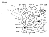
- the fixed contacts 20 formed in the bottom wall portion 11 include, as constituting members of the push switch section P, a center contact 21 (an example of "a contacted contact” in the present invention) disposed on the axis X, a lower contact 22 disposed on the outer peripheral side, and an upper contact 23 disposed on the further outer peripheral side than the lower contact 21.
- the fixed contacts 20 also include, as constituting members of the rotary switch section R, a main contact 24 disposed on a virtual circle about the axis X, a left first contact 25L and a right first contact 25R which are disposed side by side in the peripheral direction at positions spaced from the main contact 24 on this virtual circle, and a left second contact 26L and a right second contact 26R which are disposed at positions opposed to each other across the main contact 24 on the virtual circle.
- the "fixed points" 20 comprise the generic concept inclusive all of the center contact 21, the lower contact 22, the upper contact 23, the main contact 24, the left first contact 25L, the right first contact 25R, the left second contact 26L and the right second contact 26R. And, these fixed points, namely, the center contact 21, the lower contact 22, the upper contact 23, the main contact 24, the left first contact 25L, the right first contact 25R, the left second contact 26L and the right second contact 26R are formed as metal plates or metal foils made of copper alloy or the like fixed to the upper face of the bottom wall portion 11.
- lead terminals 21T, 22T, 23T, 24T, 25LT, 25RT, 26LT, 26RT electrically connected to these contacts by such technique as printed wiring are formed so as to project outward from the three lateral walls 15.
- the reference marks denoting these lead terminals comprise the reference numerals of the respective fixed contacts to which the respective lead terminals are electrically connected, with addition of the letter "T" thereto.
- the main contact 24, the left first contact 25L, the right first contact 25R, the left second contact 26L and the right second contact 26R are arranged at positions excluding the fan-shaped area extending in the area of the open portion W relative to the axis X.
- a lower switch plate 30 is formed of a disc of conductive material such as copper that is elastically deformable. And, this plate 30 includes a lower plate body 31 in the form of a dome having an upwardly projecting center, and a pair of lower projections 32 projecting outward from the outer periphery of the lower plate body 31.
- an upper switch plate 40 also is formed of a disc of conductive material such as copper that is elastically deformable and includes an upper plate body 41 in the form of a dome having an upwardly projecting center, and four upper projections 42 projecting outward from the outer periphery of the upper plate body 41.
- the lower switch plate 30 and the upper switch plate 40 are disposed one above the other, in a spaced relationship with each other by a set distance therebetween.
- the upper switch plate 40 is elastically deformed to come into contact with the upper face of the lower switch plate 30, so that this contact condition can be electrically detected.
- the lower switch plate 30 is elastically deformed, so that this lower switch plate 30 comes into contact with the center contact 21, so this contact condition can be electrically detected.
- the push switch section P is configured to be capable of detecting two steps of pressing operation.
- the deformation property is set so as to obtain different click feels, the feel of the first step operation and the feel of the second step operation, and the operation reaction force dropping significantly near the completion of the operation.
- gold plating may be provided on its opposed faces for obtaining better electric conduction.
- the protective sheet 50 includes a circular sheet body 51 formed of a flexibly deformable sheet resin material that has electrical insulating property and has a smooth surface with low friction coefficient, a central bulging portion 52 projecting upward with a curve, and cutout portions 53 formed at two positions in the outer periphery. As the retaining projections 14 come into engagement with the cutout portions 53 at the two positions, the protective sheet 50 is prevented from being rotated and is fixed in position at the same time.
- the brush unit 60 includes a ring-shaped portion 61 (an example of "a rotary member") formed of a metal plate of conductive material such as copper alloy, a left main contact shoe 62 projecting downward from a leading end of a left main arm portion 62A formed integral with the ring-shaped portion 61, a right main contact shoe 63 projecting downward from a leading end of a right main arm portion 63A, an auxiliary contact shoe 64 projecting downward from a leading end of one auxiliary arm portion 64A formed integral with the ring-shaped portion 61, and a pair of engaging recesses 65.
- a ring-shaped portion 61 an example of "a rotary member”
- a metal plate of conductive material such as copper alloy
- a left main contact shoe 62 projecting downward from a leading end of a left main arm portion 62A formed integral with the ring-shaped portion 61
- a right main contact shoe 63 projecting downward from a leading end of a right main arm portion 63A
- the outer peripheral diameters of the left main portion 62A, the right main arm portion 63A and the auxiliary arm portion 64A are set to be slightly smaller than the inner diameter of the inner peripheral face 12S of the outer wall portion 12, so that the brush unit 60 is supported to the switch main body 10 to be rotatable about the axis X.
- This brush unit 60 is supported at a position where the lower face side of the ring-shaped portion 61 is placed on the protective sheet 50 at portions in the upper faces of the pair of rib-like portions 13. Further, as the two left main arm portions 62A, the right main arm portion 63A and the auxiliary arm portion 64A are formed with the inclination projecting downward from the ring-shaped portion 61, the left main contact shoe 62, the right main contact shoe 63 and the auxiliary contact shoe 64 are caused to project downward.
- the left main contact shoe 62 and the right main contact shoe 63 are arranged at positions adjacent to each other in the peripheral direction and at a position distant therefrom, the single auxiliary contact shoe 64 is provided. Incidentally, these contact shoes are arranged on the virtual circle centering about the axis X.
- the rotor 70 includes a ring-shaped rotor body 71 formed of an insulating material such as resin and a lever 72 formed integral with the rotor body 71. And, in the lower face of the rotor 70, there are formed projections (not shown) engageable into the engaging recesses 65 of the brush unit 60. As the outer peripheral diameter of this rotor body 71 is set slightly smaller than the inner diameter of the inner peripheral face 12S of the outer wall portion 12 of the switch body 10, the rotor 70 is supported to the switch body 10 to be rotatable about the axis X.
- the cover 80 includes a cover body 81 having a shape substantially in agreement with that of the switch body 10 as seen in the plane view and forms, at five positions in the outer periphery thereof, projecting pieces 82 defining engaging holes 83. Further, at the center of the cover body 81, an aperture 84 is formed and a pressing piece 85 is formed to project downward from this aperture 84.
- the center contact 21, the lower contact 22, the upper contact 23, the lower switch plate 30, and the upper switch plate 40 together constitute the push switch section P.
- the main contact 24, the one pair of first contacts 25R, 25L, the one pair of second contacts 26R, 26L, and the two left main contact shoes 62, the right main contact shoe 63 and the one auxiliary contact shoe 64 of the brush unit 60 and the rotor 70 operated by the lever 72 together constitute the rotary switch section R.
- the lower switch plate 30, the upper switch plate 40, the protective sheet 50, the brush unit 60, the rotor 70 and the cover 80 are superposed one on another, respectively, and the cover 80 is pressed relative to the switch body 10, in the direction along the axis X.
- a plurality of projecting pieces 82 of the cover 80 are elastically deformed to the outer side, and the plurality of engaging projections 18 of the switch body 10 come into engagement with the engaging holes 83 of these projecting pieces 82, so that by the elastic resilience of the projecting pieces 82, the engaged condition of the engaging projections 18 relative to the engaging holes 83 is maintained.
- the protective sheet 50 is fixed in position and its rotation is restricted at the same time.
- the ring-shaped portion 61 of the brush unit 60 is supported.
- the two left main contact shoes 62, the right main contact shoe 63 and the one auxiliary contact shoe 64 of this brush unit 60 come into contact with the main contact 24, the left first contact 25L, the right first contact 25R, the left second contact 26L, and the right second contact 26R associated therewith, respectively (the mode of this contact will be detailed later).
- the pressing operational force is applied from the center portion of the upper plate body 41 to the center portion of the lower plate body 31, so that the center portion of the lower plate body 31 is elastically deformed to be depressed downward.
- the lower face of this center portion comes ino contact with the center contact 21, whereby electric conduction is established between the lower contact 22 and the center contact 21, hence, detection of operation to this second stage is made possible.
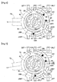
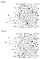
- the lever 72 can be operated to a first right operational position R1 and to a second right operational position R2. Similarly, the lever 72 can be operated to the left side, to a first left operational position L1 and to a second left operational position L2.
- the lever 72 When the lever 72 is located at the neutral posture N, as shown in Fig. 6 , the left main contact shoe 62 and the right main contact shoe 63 are in contact with the main contact 24, thus being in electric conduction therewith.
- the auxiliary contact shoe 64 is located at an intermediate position between the left first contact 25L and the right first contact 25R, being not in contact with either of these.
- the main contact 24 is set to the ground-level potential. And, by identifying a fixed contact 20 whose potential has dropped to the ground level, the switch operation is detected. Instead, however, a desired potential may be impressed to this main contact 24. In this alternative case, a switch operation will be detected as a rise in the potential of the fixed contact 20.
- the rotational operation to one side e.g. to the left side
- the rotational operation to the other side e.g. to the right side
- rotational operations to the fourth positions are made possible, even excluding the detection of the neutral posture N.
- the construction requires only three contact shoes to be formed in the outer periphery of the brush unit 60. In comparison with e.g. an arrangement having four contact shoes in correspondence with four postures, it is possible to realize compactness of the brush unit 60 and to reduce the area where the contacts to come into contact with the contact shoes are disposed. So that, the compactness of the combination switch can be realized.
- the present invention can be used in not only a digital camera, but also in audio devices and mobile phones.
Landscapes
- Switches With Compound Operations (AREA)
- Rotary Switch, Piano Key Switch, And Lever Switch (AREA)
Applications Claiming Priority (1)
| Application Number | Priority Date | Filing Date | Title |
|---|---|---|---|
| JP2009133299A JP4886816B2 (ja) | 2009-06-02 | 2009-06-02 | 複合スイッチ |
Publications (3)
| Publication Number | Publication Date |
|---|---|
| EP2259280A2 true EP2259280A2 (fr) | 2010-12-08 |
| EP2259280A3 EP2259280A3 (fr) | 2011-03-30 |
| EP2259280B1 EP2259280B1 (fr) | 2012-01-25 |
Family
ID=42674620
Family Applications (1)
| Application Number | Title | Priority Date | Filing Date |
|---|---|---|---|
| EP10005264A Active EP2259280B1 (fr) | 2009-06-02 | 2010-05-20 | Interrupteur à combinaison |
Country Status (8)
| Country | Link |
|---|---|
| US (1) | US8217282B2 (fr) |
| EP (1) | EP2259280B1 (fr) |
| JP (1) | JP4886816B2 (fr) |
| KR (1) | KR101204171B1 (fr) |
| CN (1) | CN101908431B (fr) |
| AT (1) | ATE543193T1 (fr) |
| CA (1) | CA2705958C (fr) |
| TW (1) | TWI390566B (fr) |
Families Citing this family (4)
| Publication number | Priority date | Publication date | Assignee | Title |
|---|---|---|---|---|
| JP4531793B2 (ja) * | 2007-06-11 | 2010-08-25 | ホシデン株式会社 | 複合操作型入力装置 |
| DE102015215188B3 (de) * | 2015-08-10 | 2016-12-29 | Ellenberger & Poensgen Gmbh | Schaltsystem |
| JP7340490B2 (ja) * | 2020-04-15 | 2023-09-07 | ホシデン株式会社 | シートベルト着脱検出スイッチ |
| WO2022263914A1 (fr) * | 2021-06-16 | 2022-12-22 | Nikhil Kachattiyawar | Système pour ensemble commutateur hybride et ensemble commutateur rotatif pour commander des appareils |
Citations (1)
| Publication number | Priority date | Publication date | Assignee | Title |
|---|---|---|---|---|
| JP2008177098A (ja) | 2007-01-19 | 2008-07-31 | Hosiden Corp | 複合スイッチ |
Family Cites Families (15)
| Publication number | Priority date | Publication date | Assignee | Title |
|---|---|---|---|---|
| FR2759199B1 (fr) * | 1997-01-31 | 1999-03-26 | Itt Composants Instr | Dispositif modulaire de commutation electrique |
| JP2001135197A (ja) * | 1999-11-02 | 2001-05-18 | Matsushita Electric Ind Co Ltd | 押圧・回転操作型電子部品 |
| US6236002B1 (en) * | 2000-05-03 | 2001-05-22 | Shin Jiuh Corp. | Multiple switch assembly including cam operated rotary switch contacts and axially located pushbutton switch |
| JP2001357758A (ja) * | 2000-06-12 | 2001-12-26 | Alps Electric Co Ltd | 複合操作型入力装置 |
| JP4620894B2 (ja) * | 2001-04-06 | 2011-01-26 | キヤノン株式会社 | 電子機器 |
| JP3864812B2 (ja) * | 2002-03-07 | 2007-01-10 | 松下電器産業株式会社 | 複合操作型電子部品 |
| US6680444B1 (en) * | 2002-10-30 | 2004-01-20 | Shin-Jiuh Corp. | Structure of a switch for electronic device |
| JP2005108570A (ja) * | 2003-09-29 | 2005-04-21 | Mitsumi Electric Co Ltd | 複合操作型スイッチ装置 |
| CN2650318Y (zh) * | 2003-11-03 | 2004-10-20 | 郭万国 | 选择性按键复合式开关结构 |
| TWM291597U (en) * | 2005-04-01 | 2006-06-01 | Hon Hai Prec Ind Co Ltd | A pushbutton and rotary switch |
| JP4635774B2 (ja) * | 2005-08-03 | 2011-02-23 | パナソニック株式会社 | 複合操作型スイッチ |
| JP4306669B2 (ja) * | 2005-10-11 | 2009-08-05 | オムロン株式会社 | 操作入力装置およびこれを用いた電子機器 |
| JP4353964B2 (ja) * | 2006-06-26 | 2009-10-28 | ホシデン株式会社 | 複合操作型入力装置 |
| JP5157158B2 (ja) * | 2006-12-25 | 2013-03-06 | カシオ計算機株式会社 | 接点装置 |
| JP4521450B2 (ja) * | 2008-03-14 | 2010-08-11 | ホシデン株式会社 | 複合操作型入力装置 |
-
2009
- 2009-06-02 JP JP2009133299A patent/JP4886816B2/ja active Active
-
2010
- 2010-04-16 KR KR1020100035352A patent/KR101204171B1/ko active Active
- 2010-04-21 TW TW099112508A patent/TWI390566B/zh active
- 2010-05-20 EP EP10005264A patent/EP2259280B1/fr active Active
- 2010-05-20 AT AT10005264T patent/ATE543193T1/de active
- 2010-05-21 US US12/784,833 patent/US8217282B2/en active Active
- 2010-05-31 CA CA2705958A patent/CA2705958C/fr active Active
- 2010-06-01 CN CN201010200329.4A patent/CN101908431B/zh active Active
Patent Citations (1)
| Publication number | Priority date | Publication date | Assignee | Title |
|---|---|---|---|---|
| JP2008177098A (ja) | 2007-01-19 | 2008-07-31 | Hosiden Corp | 複合スイッチ |
Also Published As
| Publication number | Publication date |
|---|---|
| US20100300851A1 (en) | 2010-12-02 |
| JP4886816B2 (ja) | 2012-02-29 |
| TWI390566B (zh) | 2013-03-21 |
| KR20100130143A (ko) | 2010-12-10 |
| CN101908431B (zh) | 2014-08-20 |
| US8217282B2 (en) | 2012-07-10 |
| JP2010282756A (ja) | 2010-12-16 |
| KR101204171B1 (ko) | 2012-11-22 |
| TW201110177A (en) | 2011-03-16 |
| EP2259280B1 (fr) | 2012-01-25 |
| CA2705958A1 (fr) | 2010-12-02 |
| EP2259280A3 (fr) | 2011-03-30 |
| CN101908431A (zh) | 2010-12-08 |
| ATE543193T1 (de) | 2012-02-15 |
| CA2705958C (fr) | 2016-08-02 |
Similar Documents
| Publication | Publication Date | Title |
|---|---|---|
| JP4315983B2 (ja) | 複合スイッチ | |
| EP2755220B1 (fr) | Commutateur | |
| EP1026713B1 (fr) | Pieces electroniques de type a fonctionnement par pression et rotation et materiel de terminal de reseau comprenant ces pieces electroniques | |
| JP3960132B2 (ja) | 多方向操作スイッチおよびこれを用いた多方向入力装置 | |
| EP2259280B1 (fr) | Interrupteur à combinaison | |
| US6605786B2 (en) | Electrical switch single sliding/rotary actuator | |
| JP3824723B2 (ja) | 多方向スイッチ | |
| JP4635774B2 (ja) | 複合操作型スイッチ | |
| JP4026211B2 (ja) | プッシュオンスイッチ | |
| JPH11312442A (ja) | 多方向スイッチおよびこの多方向スイッチを用いた電子機器 | |
| CN102194597A (zh) | 开关组件、操作开关及便携式终端 | |
| JP4937994B2 (ja) | 多方向スライド式スイッチ | |
| US7301111B2 (en) | Slide switch | |
| JP4106924B2 (ja) | 多方向操作スイッチ | |
| JPH071713Y2 (ja) | 中点自動復帰式ロータリスイッチ | |
| JP2003234047A (ja) | 多方向操作スイッチ | |
| JP5257013B2 (ja) | 複合操作型スイッチ | |
| JP2003100183A (ja) | スイッチ装置及びこれを備えた小型電子機器 | |
| JP2005183152A (ja) | 多方向スイッチ | |
| JP2000067701A (ja) | 多方向スイッチ | |
| JP2007103140A (ja) | 多方向入力装置 | |
| JP2007066637A (ja) | 複合操作型スイッチ | |
| JP2003162942A (ja) | 多方向スイッチ | |
| JP2007103275A (ja) | 入力装置 |
Legal Events
| Date | Code | Title | Description |
|---|---|---|---|
| PUAI | Public reference made under article 153(3) epc to a published international application that has entered the european phase |
Free format text: ORIGINAL CODE: 0009012 |
|
| AK | Designated contracting states |
Kind code of ref document: A2 Designated state(s): AL AT BE BG CH CY CZ DE DK EE ES FI FR GB GR HR HU IE IS IT LI LT LU LV MC MK MT NL NO PL PT RO SE SI SK SM TR |
|
| AX | Request for extension of the european patent |
Extension state: BA ME RS |
|
| PUAL | Search report despatched |
Free format text: ORIGINAL CODE: 0009013 |
|
| AK | Designated contracting states |
Kind code of ref document: A3 Designated state(s): AL AT BE BG CH CY CZ DE DK EE ES FI FR GB GR HR HU IE IS IT LI LT LU LV MC MK MT NL NO PL PT RO SE SI SK SM TR |
|
| AX | Request for extension of the european patent |
Extension state: BA ME RS |
|
| GRAP | Despatch of communication of intention to grant a patent |
Free format text: ORIGINAL CODE: EPIDOSNIGR1 |
|
| 17P | Request for examination filed |
Effective date: 20110629 |
|
| RIC1 | Information provided on ipc code assigned before grant |
Ipc: H01H 13/64 20060101AFI20110719BHEP Ipc: H01H 19/00 20060101ALI20110719BHEP Ipc: H01H 89/00 20060101ALI20110719BHEP |
|
| GRAS | Grant fee paid |
Free format text: ORIGINAL CODE: EPIDOSNIGR3 |
|
| GRAA | (expected) grant |
Free format text: ORIGINAL CODE: 0009210 |
|
| AK | Designated contracting states |
Kind code of ref document: B1 Designated state(s): AL AT BE BG CH CY CZ DE DK EE ES FI FR GB GR HR HU IE IS IT LI LT LU LV MC MK MT NL NO PL PT RO SE SI SK SM TR |
|
| REG | Reference to a national code |
Ref country code: GB Ref legal event code: FG4D |
|
| REG | Reference to a national code |
Ref country code: CH Ref legal event code: EP |
|
| REG | Reference to a national code |
Ref country code: AT Ref legal event code: REF Ref document number: 543193 Country of ref document: AT Kind code of ref document: T Effective date: 20120215 |
|
| REG | Reference to a national code |
Ref country code: IE Ref legal event code: FG4D |
|
| REG | Reference to a national code |
Ref country code: DE Ref legal event code: R096 Ref document number: 602010000711 Country of ref document: DE Effective date: 20120322 |
|
| REG | Reference to a national code |
Ref country code: DE Ref legal event code: R082 Ref document number: 602010000711 Country of ref document: DE Representative=s name: LEMCKE, BROMMER & PARTNER, PATENTANWAELTE, DE Ref country code: DE Ref legal event code: R082 Ref document number: 602010000711 Country of ref document: DE Representative=s name: LEMCKE, BROMMER & PARTNER, PATENTANWAELTE PART, DE |
|
| REG | Reference to a national code |
Ref country code: NL Ref legal event code: VDEP Effective date: 20120125 |
|
| LTIE | Lt: invalidation of european patent or patent extension |
Effective date: 20120125 |
|
| PG25 | Lapsed in a contracting state [announced via postgrant information from national office to epo] |
Ref country code: NO Free format text: LAPSE BECAUSE OF FAILURE TO SUBMIT A TRANSLATION OF THE DESCRIPTION OR TO PAY THE FEE WITHIN THE PRESCRIBED TIME-LIMIT Effective date: 20120425 Ref country code: NL Free format text: LAPSE BECAUSE OF FAILURE TO SUBMIT A TRANSLATION OF THE DESCRIPTION OR TO PAY THE FEE WITHIN THE PRESCRIBED TIME-LIMIT Effective date: 20120125 Ref country code: IS Free format text: LAPSE BECAUSE OF FAILURE TO SUBMIT A TRANSLATION OF THE DESCRIPTION OR TO PAY THE FEE WITHIN THE PRESCRIBED TIME-LIMIT Effective date: 20120525 Ref country code: BG Free format text: LAPSE BECAUSE OF FAILURE TO SUBMIT A TRANSLATION OF THE DESCRIPTION OR TO PAY THE FEE WITHIN THE PRESCRIBED TIME-LIMIT Effective date: 20120425 Ref country code: BE Free format text: LAPSE BECAUSE OF FAILURE TO SUBMIT A TRANSLATION OF THE DESCRIPTION OR TO PAY THE FEE WITHIN THE PRESCRIBED TIME-LIMIT Effective date: 20120125 Ref country code: HR Free format text: LAPSE BECAUSE OF FAILURE TO SUBMIT A TRANSLATION OF THE DESCRIPTION OR TO PAY THE FEE WITHIN THE PRESCRIBED TIME-LIMIT Effective date: 20120125 Ref country code: LT Free format text: LAPSE BECAUSE OF FAILURE TO SUBMIT A TRANSLATION OF THE DESCRIPTION OR TO PAY THE FEE WITHIN THE PRESCRIBED TIME-LIMIT Effective date: 20120125 |
|
| PG25 | Lapsed in a contracting state [announced via postgrant information from national office to epo] |
Ref country code: PL Free format text: LAPSE BECAUSE OF FAILURE TO SUBMIT A TRANSLATION OF THE DESCRIPTION OR TO PAY THE FEE WITHIN THE PRESCRIBED TIME-LIMIT Effective date: 20120125 Ref country code: LV Free format text: LAPSE BECAUSE OF FAILURE TO SUBMIT A TRANSLATION OF THE DESCRIPTION OR TO PAY THE FEE WITHIN THE PRESCRIBED TIME-LIMIT Effective date: 20120125 Ref country code: GR Free format text: LAPSE BECAUSE OF FAILURE TO SUBMIT A TRANSLATION OF THE DESCRIPTION OR TO PAY THE FEE WITHIN THE PRESCRIBED TIME-LIMIT Effective date: 20120426 Ref country code: PT Free format text: LAPSE BECAUSE OF FAILURE TO SUBMIT A TRANSLATION OF THE DESCRIPTION OR TO PAY THE FEE WITHIN THE PRESCRIBED TIME-LIMIT Effective date: 20120525 |
|
| REG | Reference to a national code |
Ref country code: AT Ref legal event code: MK05 Ref document number: 543193 Country of ref document: AT Kind code of ref document: T Effective date: 20120125 |
|
| PG25 | Lapsed in a contracting state [announced via postgrant information from national office to epo] |
Ref country code: CY Free format text: LAPSE BECAUSE OF FAILURE TO SUBMIT A TRANSLATION OF THE DESCRIPTION OR TO PAY THE FEE WITHIN THE PRESCRIBED TIME-LIMIT Effective date: 20120125 |
|
| PG25 | Lapsed in a contracting state [announced via postgrant information from national office to epo] |
Ref country code: SI Free format text: LAPSE BECAUSE OF FAILURE TO SUBMIT A TRANSLATION OF THE DESCRIPTION OR TO PAY THE FEE WITHIN THE PRESCRIBED TIME-LIMIT Effective date: 20120125 Ref country code: SE Free format text: LAPSE BECAUSE OF FAILURE TO SUBMIT A TRANSLATION OF THE DESCRIPTION OR TO PAY THE FEE WITHIN THE PRESCRIBED TIME-LIMIT Effective date: 20120125 Ref country code: DK Free format text: LAPSE BECAUSE OF FAILURE TO SUBMIT A TRANSLATION OF THE DESCRIPTION OR TO PAY THE FEE WITHIN THE PRESCRIBED TIME-LIMIT Effective date: 20120125 Ref country code: RO Free format text: LAPSE BECAUSE OF FAILURE TO SUBMIT A TRANSLATION OF THE DESCRIPTION OR TO PAY THE FEE WITHIN THE PRESCRIBED TIME-LIMIT Effective date: 20120125 Ref country code: CZ Free format text: LAPSE BECAUSE OF FAILURE TO SUBMIT A TRANSLATION OF THE DESCRIPTION OR TO PAY THE FEE WITHIN THE PRESCRIBED TIME-LIMIT Effective date: 20120125 Ref country code: EE Free format text: LAPSE BECAUSE OF FAILURE TO SUBMIT A TRANSLATION OF THE DESCRIPTION OR TO PAY THE FEE WITHIN THE PRESCRIBED TIME-LIMIT Effective date: 20120125 |
|
| PG25 | Lapsed in a contracting state [announced via postgrant information from national office to epo] |
Ref country code: IT Free format text: LAPSE BECAUSE OF FAILURE TO SUBMIT A TRANSLATION OF THE DESCRIPTION OR TO PAY THE FEE WITHIN THE PRESCRIBED TIME-LIMIT Effective date: 20120125 Ref country code: SK Free format text: LAPSE BECAUSE OF FAILURE TO SUBMIT A TRANSLATION OF THE DESCRIPTION OR TO PAY THE FEE WITHIN THE PRESCRIBED TIME-LIMIT Effective date: 20120125 |
|
| PLBE | No opposition filed within time limit |
Free format text: ORIGINAL CODE: 0009261 |
|
| STAA | Information on the status of an ep patent application or granted ep patent |
Free format text: STATUS: NO OPPOSITION FILED WITHIN TIME LIMIT |
|
| PG25 | Lapsed in a contracting state [announced via postgrant information from national office to epo] |
Ref country code: MC Free format text: LAPSE BECAUSE OF NON-PAYMENT OF DUE FEES Effective date: 20120531 |
|
| 26N | No opposition filed |
Effective date: 20121026 |
|
| PG25 | Lapsed in a contracting state [announced via postgrant information from national office to epo] |
Ref country code: AT Free format text: LAPSE BECAUSE OF FAILURE TO SUBMIT A TRANSLATION OF THE DESCRIPTION OR TO PAY THE FEE WITHIN THE PRESCRIBED TIME-LIMIT Effective date: 20120125 |
|
| REG | Reference to a national code |
Ref country code: DE Ref legal event code: R097 Ref document number: 602010000711 Country of ref document: DE Effective date: 20121026 |
|
| REG | Reference to a national code |
Ref country code: IE Ref legal event code: MM4A |
|
| PG25 | Lapsed in a contracting state [announced via postgrant information from national office to epo] |
Ref country code: MK Free format text: LAPSE BECAUSE OF FAILURE TO SUBMIT A TRANSLATION OF THE DESCRIPTION OR TO PAY THE FEE WITHIN THE PRESCRIBED TIME-LIMIT Effective date: 20120125 |
|
| PG25 | Lapsed in a contracting state [announced via postgrant information from national office to epo] |
Ref country code: IE Free format text: LAPSE BECAUSE OF NON-PAYMENT OF DUE FEES Effective date: 20120520 Ref country code: ES Free format text: LAPSE BECAUSE OF FAILURE TO SUBMIT A TRANSLATION OF THE DESCRIPTION OR TO PAY THE FEE WITHIN THE PRESCRIBED TIME-LIMIT Effective date: 20120506 |
|
| PG25 | Lapsed in a contracting state [announced via postgrant information from national office to epo] |
Ref country code: MT Free format text: LAPSE BECAUSE OF FAILURE TO SUBMIT A TRANSLATION OF THE DESCRIPTION OR TO PAY THE FEE WITHIN THE PRESCRIBED TIME-LIMIT Effective date: 20120125 |
|
| PG25 | Lapsed in a contracting state [announced via postgrant information from national office to epo] |
Ref country code: AL Free format text: LAPSE BECAUSE OF FAILURE TO SUBMIT A TRANSLATION OF THE DESCRIPTION OR TO PAY THE FEE WITHIN THE PRESCRIBED TIME-LIMIT Effective date: 20120125 |
|
| PG25 | Lapsed in a contracting state [announced via postgrant information from national office to epo] |
Ref country code: TR Free format text: LAPSE BECAUSE OF FAILURE TO SUBMIT A TRANSLATION OF THE DESCRIPTION OR TO PAY THE FEE WITHIN THE PRESCRIBED TIME-LIMIT Effective date: 20120125 |
|
| PG25 | Lapsed in a contracting state [announced via postgrant information from national office to epo] |
Ref country code: LU Free format text: LAPSE BECAUSE OF NON-PAYMENT OF DUE FEES Effective date: 20120520 Ref country code: SM Free format text: LAPSE BECAUSE OF FAILURE TO SUBMIT A TRANSLATION OF THE DESCRIPTION OR TO PAY THE FEE WITHIN THE PRESCRIBED TIME-LIMIT Effective date: 20120125 |
|
| PG25 | Lapsed in a contracting state [announced via postgrant information from national office to epo] |
Ref country code: HU Free format text: LAPSE BECAUSE OF FAILURE TO SUBMIT A TRANSLATION OF THE DESCRIPTION OR TO PAY THE FEE WITHIN THE PRESCRIBED TIME-LIMIT Effective date: 20100520 |
|
| REG | Reference to a national code |
Ref country code: CH Ref legal event code: PL |
|
| PG25 | Lapsed in a contracting state [announced via postgrant information from national office to epo] |
Ref country code: LI Free format text: LAPSE BECAUSE OF NON-PAYMENT OF DUE FEES Effective date: 20140531 Ref country code: CH Free format text: LAPSE BECAUSE OF NON-PAYMENT OF DUE FEES Effective date: 20140531 |
|
| REG | Reference to a national code |
Ref country code: FR Ref legal event code: PLFP Year of fee payment: 7 |
|
| REG | Reference to a national code |
Ref country code: FR Ref legal event code: PLFP Year of fee payment: 8 |
|
| REG | Reference to a national code |
Ref country code: FR Ref legal event code: PLFP Year of fee payment: 9 |
|
| PGFP | Annual fee paid to national office [announced via postgrant information from national office to epo] |
Ref country code: FI Payment date: 20250423 Year of fee payment: 16 |
|
| PGFP | Annual fee paid to national office [announced via postgrant information from national office to epo] |
Ref country code: DE Payment date: 20250509 Year of fee payment: 16 |
|
| PGFP | Annual fee paid to national office [announced via postgrant information from national office to epo] |
Ref country code: GB Payment date: 20250422 Year of fee payment: 16 |
|
| PGFP | Annual fee paid to national office [announced via postgrant information from national office to epo] |
Ref country code: FR Payment date: 20250528 Year of fee payment: 16 |