EP2260324B1 - Mesure de la distance et de l'orientation d'un objet - Google Patents
Mesure de la distance et de l'orientation d'un objet Download PDFInfo
- Publication number
- EP2260324B1 EP2260324B1 EP09726654A EP09726654A EP2260324B1 EP 2260324 B1 EP2260324 B1 EP 2260324B1 EP 09726654 A EP09726654 A EP 09726654A EP 09726654 A EP09726654 A EP 09726654A EP 2260324 B1 EP2260324 B1 EP 2260324B1
- Authority
- EP
- European Patent Office
- Prior art keywords
- function
- measurement
- light
- distance
- period
- Prior art date
- Legal status (The legal status is an assumption and is not a legal conclusion. Google has not performed a legal analysis and makes no representation as to the accuracy of the status listed.)
- Not-in-force
Links
- 238000005259 measurement Methods 0.000 title claims description 37
- 238000000034 method Methods 0.000 claims abstract description 19
- 230000000737 periodic effect Effects 0.000 claims 4
- 239000013307 optical fiber Substances 0.000 description 25
- 239000000835 fiber Substances 0.000 description 19
- 238000006073 displacement reaction Methods 0.000 description 7
- 238000003384 imaging method Methods 0.000 description 4
- 230000003287 optical effect Effects 0.000 description 4
- 238000005516 engineering process Methods 0.000 description 3
- 230000004298 light response Effects 0.000 description 3
- 238000010586 diagram Methods 0.000 description 2
- 238000012986 modification Methods 0.000 description 2
- 230000004048 modification Effects 0.000 description 2
- 239000000463 material Substances 0.000 description 1
- 230000000630 rising effect Effects 0.000 description 1
- 230000001360 synchronised effect Effects 0.000 description 1
Images






Classifications
-
- G—PHYSICS
- G01—MEASURING; TESTING
- G01B—MEASURING LENGTH, THICKNESS OR SIMILAR LINEAR DIMENSIONS; MEASURING ANGLES; MEASURING AREAS; MEASURING IRREGULARITIES OF SURFACES OR CONTOURS
- G01B11/00—Measuring arrangements characterised by the use of optical techniques
- G01B11/002—Measuring arrangements characterised by the use of optical techniques for measuring two or more coordinates
-
- G—PHYSICS
- G01—MEASURING; TESTING
- G01B—MEASURING LENGTH, THICKNESS OR SIMILAR LINEAR DIMENSIONS; MEASURING ANGLES; MEASURING AREAS; MEASURING IRREGULARITIES OF SURFACES OR CONTOURS
- G01B11/00—Measuring arrangements characterised by the use of optical techniques
- G01B11/02—Measuring arrangements characterised by the use of optical techniques for measuring length, width or thickness
- G01B11/026—Measuring arrangements characterised by the use of optical techniques for measuring length, width or thickness by measuring distance between sensor and object
-
- G—PHYSICS
- G01—MEASURING; TESTING
- G01B—MEASURING LENGTH, THICKNESS OR SIMILAR LINEAR DIMENSIONS; MEASURING ANGLES; MEASURING AREAS; MEASURING IRREGULARITIES OF SURFACES OR CONTOURS
- G01B11/00—Measuring arrangements characterised by the use of optical techniques
- G01B11/26—Measuring arrangements characterised by the use of optical techniques for measuring angles or tapers; for testing the alignment of axes
-
- G—PHYSICS
- G01—MEASURING; TESTING
- G01S—RADIO DIRECTION-FINDING; RADIO NAVIGATION; DETERMINING DISTANCE OR VELOCITY BY USE OF RADIO WAVES; LOCATING OR PRESENCE-DETECTING BY USE OF THE REFLECTION OR RERADIATION OF RADIO WAVES; ANALOGOUS ARRANGEMENTS USING OTHER WAVES
- G01S17/00—Systems using the reflection or reradiation of electromagnetic waves other than radio waves, e.g. lidar systems
- G01S17/02—Systems using the reflection of electromagnetic waves other than radio waves
- G01S17/06—Systems determining position data of a target
- G01S17/08—Systems determining position data of a target for measuring distance only
-
- G—PHYSICS
- G01—MEASURING; TESTING
- G01S—RADIO DIRECTION-FINDING; RADIO NAVIGATION; DETERMINING DISTANCE OR VELOCITY BY USE OF RADIO WAVES; LOCATING OR PRESENCE-DETECTING BY USE OF THE REFLECTION OR RERADIATION OF RADIO WAVES; ANALOGOUS ARRANGEMENTS USING OTHER WAVES
- G01S17/00—Systems using the reflection or reradiation of electromagnetic waves other than radio waves, e.g. lidar systems
- G01S17/87—Combinations of systems using electromagnetic waves other than radio waves
- G01S17/875—Combinations of systems using electromagnetic waves other than radio waves for determining attitude
Definitions
- This invention relates to an optical sensor and methods for non-contact measuring of a distance and orientation of a surface and more particularly for measurement using a fiber optics displacement sensor.
- CTP computer-to-plate
- Figure 1A shows the functionality of a sensor according to U.S. Patent No. 4,801,799 , with media 130 oriented at a 90 degree angle to the sensor optical axis.
- Figure 1B shows media 130 oriented at an angle other than 90 degrees. In both cases, the distance between media 130 and the outlet of the optical fiber 110 is identical.
- Figure 1B shows the sensor functionality with a tilted orientation of media 130.
- the light sensor 150 will receive smaller amounts of the reflected light energy or none at all.
- a slight change in the media 130 orientation angle might lead to the deviation of light sensor 150 output signal even though the distance between the media and the fiber outlet does not change.
- the media 130 orientation angle may significantly change the light sensor 150 output signals thus increasing the measuring errors or making measurements impossible.
- WO 97/29342 Al international patent application discloses an optical measurement system to determine the position and the orientation of an object in three dimensions.
- US 5,073,714 patent discloses a device and a method for detecting and measuring the flutter of a web material in a web handling machine.
- the flutter of the web is determined from infrared light scattered from the web.
- the orientation or shape of the surface, or head to sleeve distance measurement often varies. In those cases the fiber sensor errors caused by media orientation or shape variances becomes a substantial disadvantage of the measurement sensor. Additionally, imaging head alignment deviations or sleeve or drum eccentricity changes are also affect media-to-sensor distance measurements.
- An object of this invention is to provide a new and improved optical fiber displacement sensor device capable of providing measurements between sensor and non-flat shape surfaces or flat surfaces positioned within the range of angles between the surface and sensor axis.
- a method for measuring a distance between an object and a light source and sensing an orientation of the object includes applying light from a plurality of light sources on the object; detecting a reflected energy level from an object; measuring the reflected energy level from the object; computing a distance calibration function indicating the relation to the distance between the object and the light source; determining at least one measuring range indicated by a minimum value and a maximum value within the distance calibration function; computing an angle calibration function indicating energy level relation sampled at predetermined time slots within periods of a modulation function; and modulating each of the plurality of light sources with the modulation function such that a total energy applied from the plurality of light sources on the object during the time of the light emission is represented by a light emission predetermined function.
- the light sensor response signal measured at any fixed time within the modulation period T is a function of media-to-fiber distance and the present invention provides for measuring distance between the media and sensor even at the case where media is oriented at other than a 90 degree angle with respect to the optical fiber sensor light emission axis, or the media having a non-flat shape.
- the distance is determined by the light sensor response, measured at a fixed and predetermined point of modulation period, while angle direction and value is determined by a phase and amplitude of the signal.
- the media In the case wherein the media is oriented perpendicular with respect to the light emission axis, then the sum of the emitted light measures will stay constant, regardless of the type of modulated or un-modulated light sensor response, which is a function of the media-to-fiber distance. In the case wherein the media is positioned non-perpendicular in respect to the light emission axis or has a non-flat shape, then the measured light sensor output signal will become modulated, and the phase and amplitude of this signal will point to the direction and value of the deflection angle respectively.
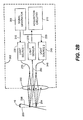
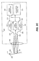
- FIGS 2A-2C are a schematic representations of optical fiber displacement apparatus according to the present invention, referred to in general by numeral 10.
- Optical fiber displacement apparatus 10 consists of signal generator 205, which generates control signals 215 and 220 for providing light modulation of light source 230 and light source 240.
- Optical fibers 235 and 245 conduct light from the light sources 230 and 240 respectively.
- Lens for focus light beams comes from optical fibers 235 and 245 on media 256, and light sensor 270 measures the reflected light from media 256 coming through the lens 250 and the optical fiber 260.
- the reflected light through light sensor 270 is acquired by the acquisition circuitry 210 and analyzed.
- Sensor configuration might comprise more than two emitting fibers and the single light sensor 270.
- the signal generator 205 issues control signals 215 and 220 for light sources 230 and 240 respectively.
- the light sources can utilize laser diodes.
- the control signals deliver electrical current which stimulates the energy emitted for each of the light sources.
- the emitted light energy related to the linear range of the light source characteristic is proportional to the light source current.
- the emitted light from each of the light sources will change according to the respective light source current modulation function.
- light energy E1 of the light source 230 is pulse modulated as it is shown in Figure 4A represented by function 445 (dashed).
- the light energy E2 of the light source 240 is modulated by the similar pulses of the same amplitude and same duty cycle of 50%, but shifted by the length of one pulse (half a period) as is shown in Figure 4A by function 435.
- E 1 0.5 ⁇ T E 2
- const Equation (2) shows that the modulation signal described above provides a constant light power when it reaches the surface of the media.
- the constant power which is emitted from the light source and passed through the optical fiber being reflected from a perpendicularly oriented media and returned through the other optical fiber to the light sensor is a function of media to light source distance.
- the graphical representation of such a function is shown in Figure 3 , wherein the light sensor response, for example, is introduced by voltage signal V and the distance to media is introduced by X.
- three points; point a 302, point b 303, and point c 304, are related to the linear range 301.
- the distances Xa, Xb, and Xc are represented by respective sensor response Va, Vb, and Vc, wherein the Xa is the minimum distance detectable within the linear range and the Xc is the maximum distance respectively.
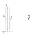
- Figure 5 shows a timing diagram for light sensor 270 response to signal V related to the distances Xa, Xb, and Xc when the total emitted power is constant and media is oriented perpendicular in respect to the light emission axis 254 ( Figure 2A ).
- the solid line 510 shows the light sensor response time dependence Vb when media is located in the middle of the distance measuring range Xb.
- the lines 520 (dotted line) and 530 (dashed line) show the light sensor 270 responses Va and Vc when media is located at Xa and Xc respectively. It can be seen as well that for any moment of time tn the media to optical fiber sensor distance may be determined by the light sensor 270 response signal measured at that time tn.
- the reflected light from media 256 will change the direction of reflection by the same angle ⁇ (dashed lines).
- Figure 2B shows media deflection in a positive direction (+ ⁇ )
- Figure 2C shows media deflection in a negative direction (- ⁇ ).
- the deflected media orientation will cause a misbalance of reflected portions of the light received by the light sensor 270 from light source 230 and light source 240.
- a portion of light from the light source 230 is reflected to the light sensor and is greater than the portion of reflected light from light source 240. Consequently the reflections of the light source 230 will affect the light sensor 270 more than reflections from the light source 240, thus resulting in a light sensor response signal modulated with frequency and phase of control signal 215.
- Figures 6A and 6B shows the light sensor 270 response behavior while light control signals 215 and 220 are modulated as described and shown by Figure 4A , and media 256 is deflected from the vertical position 255 by the angle of (+ ⁇ ).
- the acquisition circuitry 210 measures the light sensor 270 output signal synchronously with the modulation frequency. If media is oriented according to Figure 2B and is aligned within the distance Xb, the measurements are performed at designated time slots denoted by t1, t2 ... tn as illustrated in Figures 6A and 6B by solid line 510.
- the measurements read at time slots t1, ... t2n+1 will relate to the light source 230 reflections measurements, whereas the measurements read at time slots t2, ... t2n (even time slots) will relate to the light source 240 reflections respectively thus showing the different readings due to unequal reflected portions of light coming into the light sensor 270.
- the deflection angle of media is (- ⁇ ) a portion of light from the light source 240 is reflected to the light sensor 270, and is greater than the portion of reflected light from light source 230. Consequently, the reflections of the light source 240 will affect the light sensor 270 more than reflections from the light source 230. Thus, the light sensor receives a higher portion of the signal modulated with the frequency and phase of control signal 220.
- the solid line 510 of Figure 6B shows the light sensor response measured while deflected by angle (- ⁇ ) when media is located in the middle range Xb distance from the optical fiber sensor 202. As shown, the angle direction change from + ⁇ to - ⁇ leads to a phase change of the response signal. (The odd time slots are bigger than even ones while media is under the deflected angle + ⁇ and the odd time slots are smaller than even ones while media is under the deflected angle - ⁇ ).
- Figure 4A shows also the other modifications of modulation signal; triangular modulation depicted on Figure 4B and curved modulation on Figure 4C respectively.
- the solid lines 435 relate to the modulation of the light source 230 and the dashed lines 445 to the modulator light source 240.
- Figures 7A and 7B show the response curves of light sensor 270 measured while media deflected by the angle of + ⁇ located in positions Xa, Xb, and Xc and the light source control signals 215 and 220 are generated according to triangular Figure 4B and Figure 4C modulation modifications. Both of these types of modulation are complied with the Equation (4).
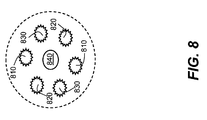
- Figure 8 shows the front end view of another sensor embodiment of the invention.
- This embodiment depicts more than two fibers used for modulation.
- This example describes three optic fiber pairs 810, 820 and 830 conducting light from the light sources and emitting light in three planes respectively, additionally a single optic fiber 840 is configured to conduct media reflections of reflected light to the light sensor 270.
- the signal generator applies control signals to each of the light sources thus providing light modulation for each fiber of the pairs 810, 820, and 830.
- the control signals provide modulation such that the total emitted light energy from all optical fiber pairs will be constant. See Equation 4.
- the acquisition circuitry measures each pair as described above, thus providing distance and angle of media.
- the media orientation is finally defined by superposition of each plane measurements.
Landscapes
- Physics & Mathematics (AREA)
- General Physics & Mathematics (AREA)
- Electromagnetism (AREA)
- Engineering & Computer Science (AREA)
- Computer Networks & Wireless Communication (AREA)
- Radar, Positioning & Navigation (AREA)
- Remote Sensing (AREA)
- Length Measuring Devices By Optical Means (AREA)
- Measurement Of Optical Distance (AREA)
- Optical Radar Systems And Details Thereof (AREA)
Claims (13)
- Procédé destiné à mesurer la distance entre un objet et une source lumineuse et détecter l'orientation dudit objet, comprenant les étapes suivantes :la transmission de lumière depuis une pluralité de sources lumineuses (230 ; 240) audit objet (256) ;la détection d'un niveau d'énergie lumineuse réfléchie par ledit objet (256) ;la mesure dudit niveau d'énergie lumineuse réfléchie par ledit objet ;et caractérisé par :le calcul de la distance (X) entre ledit objet (256) et ladite source lumineuse (230 ; 240) selon une fonction d'étalonnage de distance ;la détermination d'au moins une plage de mesure indiquée par une valeur minimale et une valeur maximale au sein de ladite fonction d'étalonnage de distance ;le calcul du niveau d'énergie lumineuse réfléchie échantillonné à des tranches de temps prédéterminées (t1, t2,..., tn) au sein de périodes d'une fonction de modulation desdites sources lumineuses selon une fonction d'étalonnage d'angle ; etla modulation de chaque source parmi ladite pluralité de sources lumineuses (230 ; 240) avec ladite fonction de modulation de telle sorte que l'énergie lumineuse totale transmise depuis ladite pluralité de sources lumineuses (230 ; 240) audit objet (256) pendant la durée de ladite émission de lumière est représentée par une fonction d'émission lumineuse périodique prédéterminée ayant une valeur constante.
- Procédé selon la revendication 1, dans lequel un profil dudit objet (256) est calculé.
- Procédé selon la revendication 1, comprenant en outre :la prise d'une première mesure de ladite énergie lumineuse réfléchie pendant une première partie d'une période de ladite fonction de modulation ;la prise d'une deuxième mesure de ladite énergie lumineuse réfléchie pendant une deuxième partie de ladite période de ladite fonction de modulation ; etsi ladite première mesure est égale à ladite deuxième mesure, alors ledit objet est positionné perpendiculaire à l'axe d'émission de lumière et ladite distance (X) entre ledit objet (256) et lesdites sources lumineuses (230 ; 240) est dérivée de ladite première mesure ou de ladite deuxième mesure en utilisant ladite fonction d'étalonnage de distance.
- Procédé selon la revendication 1, comprenant en outre :la prise d'une première mesure de ladite énergie lumineuse réfléchie pendant une première partie d'une période de ladite fonction de modulation ;la prise d'une deuxième mesure de ladite énergie lumineuse réfléchie pendant une deuxième partie de ladite période de ladite fonction de modulation ; etsi ladite première mesure est supérieure à ladite deuxième mesure, alors l'angle d'orientation (θ) dudit objet (256) est supérieur à 90 degrés par rapport à un axe d'émission de lumière et ladite distance entre ledit objet (256) et lesdites sources lumineuses (230 ; 240) est dérivée de la moyenne de ladite première mesure et de ladite deuxième mesure en utilisant ladite fonction d'étalonnage de distance et ledit angle d'orientation (θ) est dérivé de ladite fonction d'étalonnage d'angle.
- Procédé selon la revendication 1, comprenant en outre :la prise d'une première mesure de ladite énergie lumineuse réfléchie pendant une première partie d'une période de ladite fonction de modulation ;la prise d'une deuxième mesure de ladite énergie lumineuse réfléchie pendant une deuxième partie de ladite période de ladite fonction de modulation ; etsi ladite première mesure est inférieure à ladite deuxième mesure, alors l'angle d'orientation (θ) dudit objet (256) est inférieur à 90 degrés par rapport à l'axe d'émission de lumière et ladite distance entre ledit objet (256) et lesdites sources lumineuses (230 ; 240) est dérivée de la moyenne de ladite première mesure et de ladite deuxième mesure en utilisant ladite fonction d'étalonnage de distance et ledit angle d'orientation (θ) est dérivé de ladite fonction d'étalonnage d'angle.
- Procédé selon la revendication 1, dans lequel ladite fonction périodique est modulée par impulsions.
- Procédé selon la revendication 1, dans lequel ladite fonction périodique est une fonction triangulaire.
- Procédé selon la revendication 1, dans lequel ladite fonction périodique est une fonction sinus carré.
- Procédé selon la revendication 1, dans lequel lesdites sources lumineuses (230 ; 240) sont des sources laser.
- Procédé selon la revendication 1, dans lequel lesdites sources lumineuses (230 ; 240) sont des sources à diodes à émission laser.
- Procédé selon la revendication 3, dans lequel la somme de ladite première partie de période et de ladite deuxième partie de période de ladite fonction de modulation est égale à une période de ladite fonction de modulation.
- Procédé selon la revendication 3, dans lequel ladite première partie de période de ladite fonction de modulation est égale à ladite deuxième partie de période de ladite fonction de modulation.
- Procédé selon la revendication 1, dans lequel ladite plage de mesure est linéaire.
Applications Claiming Priority (2)
| Application Number | Priority Date | Filing Date | Title |
|---|---|---|---|
| US12/060,926 US7525670B1 (en) | 2008-04-02 | 2008-04-02 | Distance and orientation measurement of an object |
| PCT/US2009/001677 WO2009123676A1 (fr) | 2008-04-02 | 2009-03-17 | Mesure de la distance et de l'orientation d'un objet |
Publications (2)
| Publication Number | Publication Date |
|---|---|
| EP2260324A1 EP2260324A1 (fr) | 2010-12-15 |
| EP2260324B1 true EP2260324B1 (fr) | 2011-10-19 |
Family
ID=40568951
Family Applications (1)
| Application Number | Title | Priority Date | Filing Date |
|---|---|---|---|
| EP09726654A Not-in-force EP2260324B1 (fr) | 2008-04-02 | 2009-03-17 | Mesure de la distance et de l'orientation d'un objet |
Country Status (6)
| Country | Link |
|---|---|
| US (1) | US7525670B1 (fr) |
| EP (1) | EP2260324B1 (fr) |
| JP (1) | JP2011516857A (fr) |
| CN (1) | CN101981468B (fr) |
| AT (1) | ATE529762T1 (fr) |
| WO (1) | WO2009123676A1 (fr) |
Families Citing this family (9)
| Publication number | Priority date | Publication date | Assignee | Title |
|---|---|---|---|---|
| US20080069428A1 (en) * | 2006-08-23 | 2008-03-20 | Robert Schulkin | Single mode digital video gauging system having mechanical drawing annotations and method for same |
| US8111275B2 (en) * | 2009-05-15 | 2012-02-07 | Eastman Kodak Company | System for optically adjusting an imaging head |
| US8991062B2 (en) | 2011-12-15 | 2015-03-31 | Atkinson Audio Inc. | Locating and relocating device |
| DE102012217176A1 (de) * | 2012-09-24 | 2014-03-27 | Evonik Litarion Gmbh | Verfahren zur Ausrichtung eines Lasersensors zu einem Messobjekt |
| FR3032034B1 (fr) * | 2015-01-22 | 2019-05-17 | Institut De Radioprotection Et De Surete Nucleaire | Eprouvette d'essais et dispositif d'essais permettant une precision de mesure accrue |
| US12228684B2 (en) | 2018-08-07 | 2025-02-18 | Sony Semiconductor Solutions Corporation | Rangefinder, rangefinding system, and rangefinding method |
| CN115004055A (zh) * | 2020-03-13 | 2022-09-02 | 索尼半导体解决方案公司 | 光源驱动装置、光源装置和摄像装置 |
| GB2618378A (en) * | 2022-05-06 | 2023-11-08 | The Francis Crick Institute Ltd | Optical measurement apparatuses for use with a cutting apparatus |
| DE102023000348A1 (de) | 2023-02-06 | 2023-11-23 | Mercedes-Benz Group AG | Messverfahren zum Messen einer Spaltbreite, sowie Messvorrichtung zur Durchführung eines solchen Verfahrens |
Family Cites Families (17)
| Publication number | Priority date | Publication date | Assignee | Title |
|---|---|---|---|---|
| JPH0726806B2 (ja) | 1985-06-13 | 1995-03-29 | 株式会社日立製作所 | 距離測定装置 |
| US4709580A (en) * | 1986-02-26 | 1987-12-01 | Bd Systems, Inc. | Retroflective attitude determining system |
| US4801799A (en) | 1987-11-27 | 1989-01-31 | Honeywell Inc. | Fiber optic system for detecting vibrations of a reflecting surface |
| US5017772A (en) | 1989-05-30 | 1991-05-21 | Bei Electronics, Inc. | Fiber optic probe sensor for measuring target displacement |
| US5073714A (en) * | 1990-05-22 | 1991-12-17 | Union Camp Corporation | Method and apparatus for detecting amplitude and frequency of web flutter using infrared optical sensor |
| GB9304738D0 (en) * | 1993-03-09 | 1993-04-28 | Lucas Ind Plc | Optical displacement sensor |
| NO301191B1 (no) * | 1993-05-13 | 1997-09-22 | Cargoscan As | Anordning ved måling av gjenstanders dimensjoner |
| US6407817B1 (en) * | 1993-12-20 | 2002-06-18 | Minolta Co., Ltd. | Measuring system with improved method of reading image data of an object |
| US5793483A (en) * | 1996-02-07 | 1998-08-11 | Visidyne, Inc. | Optical measurement system |
| US5988862A (en) * | 1996-04-24 | 1999-11-23 | Cyra Technologies, Inc. | Integrated system for quickly and accurately imaging and modeling three dimensional objects |
| US20050174584A1 (en) * | 2000-07-06 | 2005-08-11 | Chalmers Scott A. | Method and apparatus for high-speed thickness mapping of patterned thin films |
| US7071460B2 (en) | 2002-06-07 | 2006-07-04 | Christopher Rush | Optical non-contact measuring probe |
| US6825484B2 (en) * | 2002-09-23 | 2004-11-30 | Creo Il. Ltd. | Surface reflectivity discriminating device |
| WO2005063114A1 (fr) * | 2003-12-25 | 2005-07-14 | National University Corporation Shizuoka University | Dispositif et procede de detection de ligne visuelle et dispositif de mesure de point de vision tridimensionnel |
| EP1555545A1 (fr) * | 2004-01-19 | 2005-07-20 | Rafael Armament Development Authority Ltd. | Télémètre à laser avec faisceaux multiples |
| CN1926790A (zh) * | 2004-03-03 | 2007-03-07 | 日本电气株式会社 | 定位系统、定位方法及其程序 |
| DE102004033114A1 (de) * | 2004-07-08 | 2006-01-26 | Ibeo Automobile Sensor Gmbh | Verfahren zur Kalibrierung eines Abstandsbildsensors |
-
2008
- 2008-04-02 US US12/060,926 patent/US7525670B1/en not_active Expired - Fee Related
-
2009
- 2009-03-17 WO PCT/US2009/001677 patent/WO2009123676A1/fr not_active Ceased
- 2009-03-17 CN CN200980111359.3A patent/CN101981468B/zh not_active Expired - Fee Related
- 2009-03-17 JP JP2011502931A patent/JP2011516857A/ja active Pending
- 2009-03-17 AT AT09726654T patent/ATE529762T1/de not_active IP Right Cessation
- 2009-03-17 EP EP09726654A patent/EP2260324B1/fr not_active Not-in-force
Also Published As
| Publication number | Publication date |
|---|---|
| EP2260324A1 (fr) | 2010-12-15 |
| ATE529762T1 (de) | 2011-11-15 |
| WO2009123676A1 (fr) | 2009-10-08 |
| JP2011516857A (ja) | 2011-05-26 |
| CN101981468A (zh) | 2011-02-23 |
| US7525670B1 (en) | 2009-04-28 |
| CN101981468B (zh) | 2013-03-27 |
Similar Documents
| Publication | Publication Date | Title |
|---|---|---|
| EP2260324B1 (fr) | Mesure de la distance et de l'orientation d'un objet | |
| EP0489474B1 (fr) | Appareil à laser pour mesurer la vitesse d'un fluide | |
| US8643849B2 (en) | Measurement systems and methods | |
| CN105572683A (zh) | 一种激光雷达采集、测距设备及其工作方法 | |
| CN104949620A (zh) | 用于光学测量装置的校正设备及校正方法 | |
| KR20030095049A (ko) | 단면이 오목거울로 가공된 광섬유를 이용한 패브리 페로공진기와 이를 이용한 원자간력 현미경에서의 외팔보탐침의 변위 측정 및 보정시스템 | |
| EP2071358A2 (fr) | Télémètre laser | |
| US6492637B1 (en) | Dimension measuring device | |
| CN105446051A (zh) | 一种激光声光扫描方法及其装置 | |
| JP2005337843A (ja) | 光学式エンコーダ | |
| EP3271749B1 (fr) | Télémètre et procédé à base de triangulation à multiples faisceaux | |
| EP0608634A2 (fr) | Dispositif pour mesurer la forme d'une surface | |
| US3476483A (en) | Motion measuring apparatus | |
| JP2008089593A (ja) | 測距装置および測距方法 | |
| EP2908101B1 (fr) | Codeur avec détection d'origine | |
| CN102679868B (zh) | 位置及深度的检出装置及方法 | |
| JP2000028317A (ja) | 光式センサ | |
| CN105783738B (zh) | 一种增量式小量程位移传感器的测量方法 | |
| US9255788B1 (en) | Measuring method for linear stage | |
| CN105783740B (zh) | 一种交替增量式测量微位移传感器的测量方法 | |
| EP3112903A1 (fr) | Vélocimètre et procédé de fabrication d'un article | |
| CN101799548B (zh) | 全光纤测速系统、相位测速方法 | |
| RU108132U1 (ru) | Устройство для измерения угловых отклонений | |
| CN220853476U (zh) | 一种测量台阶面高度的装置 | |
| CN109373935A (zh) | 激光多点双准直测量方法 |
Legal Events
| Date | Code | Title | Description |
|---|---|---|---|
| PUAI | Public reference made under article 153(3) epc to a published international application that has entered the european phase |
Free format text: ORIGINAL CODE: 0009012 |
|
| 17P | Request for examination filed |
Effective date: 20100929 |
|
| AK | Designated contracting states |
Kind code of ref document: A1 Designated state(s): AT BE BG CH CY CZ DE DK EE ES FI FR GB GR HR HU IE IS IT LI LT LU LV MC MK MT NL NO PL PT RO SE SI SK TR |
|
| AX | Request for extension of the european patent |
Extension state: AL BA RS |
|
| RIN1 | Information on inventor provided before grant (corrected) |
Inventor name: BURKATOVSKY, VITALY |
|
| GRAP | Despatch of communication of intention to grant a patent |
Free format text: ORIGINAL CODE: EPIDOSNIGR1 |
|
| DAX | Request for extension of the european patent (deleted) | ||
| GRAS | Grant fee paid |
Free format text: ORIGINAL CODE: EPIDOSNIGR3 |
|
| GRAA | (expected) grant |
Free format text: ORIGINAL CODE: 0009210 |
|
| AK | Designated contracting states |
Kind code of ref document: B1 Designated state(s): AT BE BG CH CY CZ DE DK EE ES FI FR GB GR HR HU IE IS IT LI LT LU LV MC MK MT NL NO PL PT RO SE SI SK TR |
|
| REG | Reference to a national code |
Ref country code: GB Ref legal event code: FG4D |
|
| REG | Reference to a national code |
Ref country code: CH Ref legal event code: EP |
|
| REG | Reference to a national code |
Ref country code: IE Ref legal event code: FG4D |
|
| REG | Reference to a national code |
Ref country code: DE Ref legal event code: R096 Ref document number: 602009003185 Country of ref document: DE Effective date: 20111229 |
|
| REG | Reference to a national code |
Ref country code: NL Ref legal event code: T3 |
|
| LTIE | Lt: invalidation of european patent or patent extension |
Effective date: 20111019 |
|
| REG | Reference to a national code |
Ref country code: AT Ref legal event code: MK05 Ref document number: 529762 Country of ref document: AT Kind code of ref document: T Effective date: 20111019 |
|
| PG25 | Lapsed in a contracting state [announced via postgrant information from national office to epo] |
Ref country code: LT Free format text: LAPSE BECAUSE OF FAILURE TO SUBMIT A TRANSLATION OF THE DESCRIPTION OR TO PAY THE FEE WITHIN THE PRESCRIBED TIME-LIMIT Effective date: 20111019 Ref country code: IS Free format text: LAPSE BECAUSE OF FAILURE TO SUBMIT A TRANSLATION OF THE DESCRIPTION OR TO PAY THE FEE WITHIN THE PRESCRIBED TIME-LIMIT Effective date: 20120219 Ref country code: NO Free format text: LAPSE BECAUSE OF FAILURE TO SUBMIT A TRANSLATION OF THE DESCRIPTION OR TO PAY THE FEE WITHIN THE PRESCRIBED TIME-LIMIT Effective date: 20120119 Ref country code: BE Free format text: LAPSE BECAUSE OF FAILURE TO SUBMIT A TRANSLATION OF THE DESCRIPTION OR TO PAY THE FEE WITHIN THE PRESCRIBED TIME-LIMIT Effective date: 20111019 |
|
| PG25 | Lapsed in a contracting state [announced via postgrant information from national office to epo] |
Ref country code: SI Free format text: LAPSE BECAUSE OF FAILURE TO SUBMIT A TRANSLATION OF THE DESCRIPTION OR TO PAY THE FEE WITHIN THE PRESCRIBED TIME-LIMIT Effective date: 20111019 Ref country code: GR Free format text: LAPSE BECAUSE OF FAILURE TO SUBMIT A TRANSLATION OF THE DESCRIPTION OR TO PAY THE FEE WITHIN THE PRESCRIBED TIME-LIMIT Effective date: 20120120 Ref country code: LV Free format text: LAPSE BECAUSE OF FAILURE TO SUBMIT A TRANSLATION OF THE DESCRIPTION OR TO PAY THE FEE WITHIN THE PRESCRIBED TIME-LIMIT Effective date: 20111019 Ref country code: PT Free format text: LAPSE BECAUSE OF FAILURE TO SUBMIT A TRANSLATION OF THE DESCRIPTION OR TO PAY THE FEE WITHIN THE PRESCRIBED TIME-LIMIT Effective date: 20120220 Ref country code: HR Free format text: LAPSE BECAUSE OF FAILURE TO SUBMIT A TRANSLATION OF THE DESCRIPTION OR TO PAY THE FEE WITHIN THE PRESCRIBED TIME-LIMIT Effective date: 20111019 Ref country code: SE Free format text: LAPSE BECAUSE OF FAILURE TO SUBMIT A TRANSLATION OF THE DESCRIPTION OR TO PAY THE FEE WITHIN THE PRESCRIBED TIME-LIMIT Effective date: 20111019 |
|
| PG25 | Lapsed in a contracting state [announced via postgrant information from national office to epo] |
Ref country code: CY Free format text: LAPSE BECAUSE OF FAILURE TO SUBMIT A TRANSLATION OF THE DESCRIPTION OR TO PAY THE FEE WITHIN THE PRESCRIBED TIME-LIMIT Effective date: 20111019 |
|
| PG25 | Lapsed in a contracting state [announced via postgrant information from national office to epo] |
Ref country code: EE Free format text: LAPSE BECAUSE OF FAILURE TO SUBMIT A TRANSLATION OF THE DESCRIPTION OR TO PAY THE FEE WITHIN THE PRESCRIBED TIME-LIMIT Effective date: 20111019 Ref country code: CZ Free format text: LAPSE BECAUSE OF FAILURE TO SUBMIT A TRANSLATION OF THE DESCRIPTION OR TO PAY THE FEE WITHIN THE PRESCRIBED TIME-LIMIT Effective date: 20111019 Ref country code: BG Free format text: LAPSE BECAUSE OF FAILURE TO SUBMIT A TRANSLATION OF THE DESCRIPTION OR TO PAY THE FEE WITHIN THE PRESCRIBED TIME-LIMIT Effective date: 20120119 Ref country code: DK Free format text: LAPSE BECAUSE OF FAILURE TO SUBMIT A TRANSLATION OF THE DESCRIPTION OR TO PAY THE FEE WITHIN THE PRESCRIBED TIME-LIMIT Effective date: 20111019 Ref country code: SK Free format text: LAPSE BECAUSE OF FAILURE TO SUBMIT A TRANSLATION OF THE DESCRIPTION OR TO PAY THE FEE WITHIN THE PRESCRIBED TIME-LIMIT Effective date: 20111019 |
|
| PLBE | No opposition filed within time limit |
Free format text: ORIGINAL CODE: 0009261 |
|
| STAA | Information on the status of an ep patent application or granted ep patent |
Free format text: STATUS: NO OPPOSITION FILED WITHIN TIME LIMIT |
|
| PG25 | Lapsed in a contracting state [announced via postgrant information from national office to epo] |
Ref country code: RO Free format text: LAPSE BECAUSE OF FAILURE TO SUBMIT A TRANSLATION OF THE DESCRIPTION OR TO PAY THE FEE WITHIN THE PRESCRIBED TIME-LIMIT Effective date: 20111019 Ref country code: PL Free format text: LAPSE BECAUSE OF FAILURE TO SUBMIT A TRANSLATION OF THE DESCRIPTION OR TO PAY THE FEE WITHIN THE PRESCRIBED TIME-LIMIT Effective date: 20111019 Ref country code: IT Free format text: LAPSE BECAUSE OF FAILURE TO SUBMIT A TRANSLATION OF THE DESCRIPTION OR TO PAY THE FEE WITHIN THE PRESCRIBED TIME-LIMIT Effective date: 20111019 |
|
| 26N | No opposition filed |
Effective date: 20120720 |
|
| PG25 | Lapsed in a contracting state [announced via postgrant information from national office to epo] |
Ref country code: MC Free format text: LAPSE BECAUSE OF NON-PAYMENT OF DUE FEES Effective date: 20120331 |
|
| REG | Reference to a national code |
Ref country code: DE Ref legal event code: R097 Ref document number: 602009003185 Country of ref document: DE Effective date: 20120720 |
|
| REG | Reference to a national code |
Ref country code: FR Ref legal event code: ST Effective date: 20121130 |
|
| REG | Reference to a national code |
Ref country code: IE Ref legal event code: MM4A |
|
| PG25 | Lapsed in a contracting state [announced via postgrant information from national office to epo] |
Ref country code: AT Free format text: LAPSE BECAUSE OF FAILURE TO SUBMIT A TRANSLATION OF THE DESCRIPTION OR TO PAY THE FEE WITHIN THE PRESCRIBED TIME-LIMIT Effective date: 20111019 Ref country code: FR Free format text: LAPSE BECAUSE OF NON-PAYMENT OF DUE FEES Effective date: 20120402 Ref country code: IE Free format text: LAPSE BECAUSE OF NON-PAYMENT OF DUE FEES Effective date: 20120317 |
|
| PG25 | Lapsed in a contracting state [announced via postgrant information from national office to epo] |
Ref country code: MK Free format text: LAPSE BECAUSE OF FAILURE TO SUBMIT A TRANSLATION OF THE DESCRIPTION OR TO PAY THE FEE WITHIN THE PRESCRIBED TIME-LIMIT Effective date: 20111019 |
|
| PG25 | Lapsed in a contracting state [announced via postgrant information from national office to epo] |
Ref country code: ES Free format text: LAPSE BECAUSE OF FAILURE TO SUBMIT A TRANSLATION OF THE DESCRIPTION OR TO PAY THE FEE WITHIN THE PRESCRIBED TIME-LIMIT Effective date: 20120130 |
|
| PGFP | Annual fee paid to national office [announced via postgrant information from national office to epo] |
Ref country code: GB Payment date: 20130225 Year of fee payment: 5 |
|
| PG25 | Lapsed in a contracting state [announced via postgrant information from national office to epo] |
Ref country code: FI Free format text: LAPSE BECAUSE OF FAILURE TO SUBMIT A TRANSLATION OF THE DESCRIPTION OR TO PAY THE FEE WITHIN THE PRESCRIBED TIME-LIMIT Effective date: 20111019 |
|
| PG25 | Lapsed in a contracting state [announced via postgrant information from national office to epo] |
Ref country code: MT Free format text: LAPSE BECAUSE OF FAILURE TO SUBMIT A TRANSLATION OF THE DESCRIPTION OR TO PAY THE FEE WITHIN THE PRESCRIBED TIME-LIMIT Effective date: 20111019 |
|
| REG | Reference to a national code |
Ref country code: CH Ref legal event code: PL |
|
| PG25 | Lapsed in a contracting state [announced via postgrant information from national office to epo] |
Ref country code: CH Free format text: LAPSE BECAUSE OF NON-PAYMENT OF DUE FEES Effective date: 20130331 Ref country code: LI Free format text: LAPSE BECAUSE OF NON-PAYMENT OF DUE FEES Effective date: 20130331 |
|
| PG25 | Lapsed in a contracting state [announced via postgrant information from national office to epo] |
Ref country code: TR Free format text: LAPSE BECAUSE OF FAILURE TO SUBMIT A TRANSLATION OF THE DESCRIPTION OR TO PAY THE FEE WITHIN THE PRESCRIBED TIME-LIMIT Effective date: 20111019 |
|
| PG25 | Lapsed in a contracting state [announced via postgrant information from national office to epo] |
Ref country code: LU Free format text: LAPSE BECAUSE OF NON-PAYMENT OF DUE FEES Effective date: 20120317 |
|
| PG25 | Lapsed in a contracting state [announced via postgrant information from national office to epo] |
Ref country code: HU Free format text: LAPSE BECAUSE OF FAILURE TO SUBMIT A TRANSLATION OF THE DESCRIPTION OR TO PAY THE FEE WITHIN THE PRESCRIBED TIME-LIMIT Effective date: 20090317 |
|
| GBPC | Gb: european patent ceased through non-payment of renewal fee |
Effective date: 20140317 |
|
| PG25 | Lapsed in a contracting state [announced via postgrant information from national office to epo] |
Ref country code: GB Free format text: LAPSE BECAUSE OF NON-PAYMENT OF DUE FEES Effective date: 20140317 |
|
| PGFP | Annual fee paid to national office [announced via postgrant information from national office to epo] |
Ref country code: DE Payment date: 20190215 Year of fee payment: 11 |
|
| PGFP | Annual fee paid to national office [announced via postgrant information from national office to epo] |
Ref country code: NL Payment date: 20190301 Year of fee payment: 11 |
|
| REG | Reference to a national code |
Ref country code: DE Ref legal event code: R119 Ref document number: 602009003185 Country of ref document: DE |
|
| REG | Reference to a national code |
Ref country code: NL Ref legal event code: MM Effective date: 20200401 |
|
| PG25 | Lapsed in a contracting state [announced via postgrant information from national office to epo] |
Ref country code: NL Free format text: LAPSE BECAUSE OF NON-PAYMENT OF DUE FEES Effective date: 20200401 |
|
| PG25 | Lapsed in a contracting state [announced via postgrant information from national office to epo] |
Ref country code: DE Free format text: LAPSE BECAUSE OF NON-PAYMENT OF DUE FEES Effective date: 20201001 |