EP2260794A2 - Stenteinbringungssystem - Google Patents
Stenteinbringungssystem Download PDFInfo
- Publication number
- EP2260794A2 EP2260794A2 EP10181967A EP10181967A EP2260794A2 EP 2260794 A2 EP2260794 A2 EP 2260794A2 EP 10181967 A EP10181967 A EP 10181967A EP 10181967 A EP10181967 A EP 10181967A EP 2260794 A2 EP2260794 A2 EP 2260794A2
- Authority
- EP
- European Patent Office
- Prior art keywords
- stent
- tubular member
- inner tubular
- delivery system
- stent delivery
- Prior art date
- Legal status (The legal status is an assumption and is not a legal conclusion. Google has not performed a legal analysis and makes no representation as to the accuracy of the status listed.)
- Granted
Links
- 238000010276 construction Methods 0.000 claims abstract description 28
- 229920001343 polytetrafluoroethylene Polymers 0.000 claims description 18
- 239000004810 polytetrafluoroethylene Substances 0.000 claims description 18
- 229920001903 high density polyethylene Polymers 0.000 claims description 17
- 239000004700 high-density polyethylene Substances 0.000 claims description 17
- 239000004812 Fluorinated ethylene propylene Substances 0.000 claims description 15
- 229920009441 perflouroethylene propylene Polymers 0.000 claims description 15
- 230000000694 effects Effects 0.000 claims description 13
- JOYRKODLDBILNP-UHFFFAOYSA-N Ethyl urethane Chemical compound CCOC(N)=O JOYRKODLDBILNP-UHFFFAOYSA-N 0.000 claims description 11
- 239000004952 Polyamide Substances 0.000 claims description 11
- 239000004721 Polyphenylene oxide Substances 0.000 claims description 11
- 229920002647 polyamide Polymers 0.000 claims description 11
- 229920000570 polyether Polymers 0.000 claims description 11
- -1 polytetrafluoroethylene Polymers 0.000 claims description 11
- 239000003550 marker Substances 0.000 claims description 9
- HQQADJVZYDDRJT-UHFFFAOYSA-N ethene;prop-1-ene Chemical group C=C.CC=C HQQADJVZYDDRJT-UHFFFAOYSA-N 0.000 claims description 8
- 229910045601 alloy Inorganic materials 0.000 claims description 4
- 239000000956 alloy Substances 0.000 claims description 4
- 229910000684 Cobalt-chrome Inorganic materials 0.000 claims description 3
- 239000010952 cobalt-chrome Substances 0.000 claims description 3
- 239000002952 polymeric resin Substances 0.000 claims description 3
- 229910001256 stainless steel alloy Inorganic materials 0.000 claims description 3
- 229920003002 synthetic resin Polymers 0.000 claims description 3
- 230000002028 premature Effects 0.000 abstract description 3
- 230000002265 prevention Effects 0.000 abstract description 3
- 239000010410 layer Substances 0.000 description 33
- 230000007246 mechanism Effects 0.000 description 10
- 230000000007 visual effect Effects 0.000 description 9
- 210000003813 thumb Anatomy 0.000 description 5
- 239000007943 implant Substances 0.000 description 4
- 239000000463 material Substances 0.000 description 4
- 229910001220 stainless steel Inorganic materials 0.000 description 4
- 239000010935 stainless steel Substances 0.000 description 4
- 238000002594 fluoroscopy Methods 0.000 description 3
- 229910052751 metal Inorganic materials 0.000 description 3
- 239000002184 metal Substances 0.000 description 3
- 238000000034 method Methods 0.000 description 3
- 229920001169 thermoplastic Polymers 0.000 description 3
- 239000004416 thermosoftening plastic Substances 0.000 description 3
- KDLHZDBZIXYQEI-UHFFFAOYSA-N Palladium Chemical compound [Pd] KDLHZDBZIXYQEI-UHFFFAOYSA-N 0.000 description 2
- 230000015572 biosynthetic process Effects 0.000 description 2
- 210000004204 blood vessel Anatomy 0.000 description 2
- 210000003811 finger Anatomy 0.000 description 2
- 238000000227 grinding Methods 0.000 description 2
- 210000004247 hand Anatomy 0.000 description 2
- 230000002093 peripheral effect Effects 0.000 description 2
- BASFCYQUMIYNBI-UHFFFAOYSA-N platinum Chemical compound [Pt] BASFCYQUMIYNBI-UHFFFAOYSA-N 0.000 description 2
- 230000007704 transition Effects 0.000 description 2
- 229910001020 Au alloy Inorganic materials 0.000 description 1
- 229910000566 Platinum-iridium alloy Inorganic materials 0.000 description 1
- 229920003300 Plexar® Polymers 0.000 description 1
- 229920002614 Polyether block amide Polymers 0.000 description 1
- 229910001080 W alloy Inorganic materials 0.000 description 1
- 229910001093 Zr alloy Inorganic materials 0.000 description 1
- 239000002390 adhesive tape Substances 0.000 description 1
- 210000003484 anatomy Anatomy 0.000 description 1
- 230000008859 change Effects 0.000 description 1
- 230000006835 compression Effects 0.000 description 1
- 238000007906 compression Methods 0.000 description 1
- 238000005260 corrosion Methods 0.000 description 1
- 230000007797 corrosion Effects 0.000 description 1
- 230000008878 coupling Effects 0.000 description 1
- 238000010168 coupling process Methods 0.000 description 1
- 238000005859 coupling reaction Methods 0.000 description 1
- 229920001971 elastomer Polymers 0.000 description 1
- 238000001125 extrusion Methods 0.000 description 1
- 239000000835 fiber Substances 0.000 description 1
- 238000011010 flushing procedure Methods 0.000 description 1
- PCHJSUWPFVWCPO-UHFFFAOYSA-N gold Chemical compound [Au] PCHJSUWPFVWCPO-UHFFFAOYSA-N 0.000 description 1
- 239000010931 gold Substances 0.000 description 1
- 229910052737 gold Inorganic materials 0.000 description 1
- 239000003353 gold alloy Substances 0.000 description 1
- 238000003384 imaging method Methods 0.000 description 1
- 238000002513 implantation Methods 0.000 description 1
- 238000007689 inspection Methods 0.000 description 1
- 230000013011 mating Effects 0.000 description 1
- 229910001092 metal group alloy Inorganic materials 0.000 description 1
- 239000007769 metal material Substances 0.000 description 1
- 150000002739 metals Chemical class 0.000 description 1
- 239000000203 mixture Substances 0.000 description 1
- 230000004048 modification Effects 0.000 description 1
- 238000012986 modification Methods 0.000 description 1
- 238000012544 monitoring process Methods 0.000 description 1
- 229910001000 nickel titanium Inorganic materials 0.000 description 1
- 210000000056 organ Anatomy 0.000 description 1
- 229910052763 palladium Inorganic materials 0.000 description 1
- 229910052697 platinum Inorganic materials 0.000 description 1
- HWLDNSXPUQTBOD-UHFFFAOYSA-N platinum-iridium alloy Chemical class [Ir].[Pt] HWLDNSXPUQTBOD-UHFFFAOYSA-N 0.000 description 1
- 229920000642 polymer Polymers 0.000 description 1
- 230000008569 process Effects 0.000 description 1
- 230000009467 reduction Effects 0.000 description 1
- 230000003014 reinforcing effect Effects 0.000 description 1
- 238000004904 shortening Methods 0.000 description 1
- 239000002356 single layer Substances 0.000 description 1
- 239000007787 solid Substances 0.000 description 1
- 239000000126 substance Substances 0.000 description 1
- 229910052715 tantalum Inorganic materials 0.000 description 1
- GUVRBAGPIYLISA-UHFFFAOYSA-N tantalum atom Chemical compound [Ta] GUVRBAGPIYLISA-UHFFFAOYSA-N 0.000 description 1
- XGZGDYQRJKMWNM-UHFFFAOYSA-N tantalum tungsten Chemical compound [Ta][W][Ta] XGZGDYQRJKMWNM-UHFFFAOYSA-N 0.000 description 1
- 229920006224 tie layer resin Polymers 0.000 description 1
- 230000002792 vascular Effects 0.000 description 1
- 210000005166 vasculature Anatomy 0.000 description 1
Images





Classifications
-
- A—HUMAN NECESSITIES
- A61—MEDICAL OR VETERINARY SCIENCE; HYGIENE
- A61F—FILTERS IMPLANTABLE INTO BLOOD VESSELS; PROSTHESES; DEVICES PROVIDING PATENCY TO, OR PREVENTING COLLAPSING OF, TUBULAR STRUCTURES OF THE BODY, e.g. STENTS; ORTHOPAEDIC, NURSING OR CONTRACEPTIVE DEVICES; FOMENTATION; TREATMENT OR PROTECTION OF EYES OR EARS; BANDAGES, DRESSINGS OR ABSORBENT PADS; FIRST-AID KITS
- A61F2/00—Filters implantable into blood vessels; Prostheses, i.e. artificial substitutes or replacements for parts of the body; Appliances for connecting them with the body; Devices providing patency to, or preventing collapsing of, tubular structures of the body, e.g. stents
- A61F2/95—Instruments specially adapted for placement or removal of stents or stent-grafts
- A61F2/962—Instruments specially adapted for placement or removal of stents or stent-grafts having an outer sleeve
- A61F2/966—Instruments specially adapted for placement or removal of stents or stent-grafts having an outer sleeve with relative longitudinal movement between outer sleeve and prosthesis, e.g. using a push rod
-
- A—HUMAN NECESSITIES
- A61—MEDICAL OR VETERINARY SCIENCE; HYGIENE
- A61F—FILTERS IMPLANTABLE INTO BLOOD VESSELS; PROSTHESES; DEVICES PROVIDING PATENCY TO, OR PREVENTING COLLAPSING OF, TUBULAR STRUCTURES OF THE BODY, e.g. STENTS; ORTHOPAEDIC, NURSING OR CONTRACEPTIVE DEVICES; FOMENTATION; TREATMENT OR PROTECTION OF EYES OR EARS; BANDAGES, DRESSINGS OR ABSORBENT PADS; FIRST-AID KITS
- A61F2/00—Filters implantable into blood vessels; Prostheses, i.e. artificial substitutes or replacements for parts of the body; Appliances for connecting them with the body; Devices providing patency to, or preventing collapsing of, tubular structures of the body, e.g. stents
- A61F2/95—Instruments specially adapted for placement or removal of stents or stent-grafts
- A61F2/9517—Instruments specially adapted for placement or removal of stents or stent-grafts handle assemblies therefor
Definitions
- This invention relates broadly to medical devices. More particularly this invention relates to an instrument for delivering a self-expanding vascular stent into a mammalian body and controllably releasing the sent.
- Transluminal prostheses are widely used in the medical arts for implantation in blood vessels, biliary ducts, or other similar organs of the living body. These prostheses are commonly known as stents and are used to maintain, open, or dilate tubular anatomical structures.
- Stents are either balloon expandable or self-expanding.
- Balloon expandable stents are typically made from a solid tube of stainless steel. Thereafter, a series of cuts are made in the wall of the stent.
- the stent has a first smaller diameter configuration which permits the stent to be delivered through the human vasculature by being crimped onto a balloon catheter.
- the stent also has a second, expanded diameter configuration, upon the application, by the balloon catheter, from the interior of the tubular shaped member of a radially, outwardly directed force.
- Self-expanding stents act like springs and recover to their expanded or implanted configuration after being compressed. As such, the stent is inserted into a blood vessel in a compressed state and then released at a site to deploy into an expanded state.
- One type of self-expanding stent is composed of a plurality of individually rigid but flexible and elastic thread elements defining a radially self-expanding helix. This type of stent is known in the art as a "braided stent". Placement of such stents in a body vessel can be achieved by a device which comprises an outer catheter for holding the stent at its distal end, and an inner piston which pushes the stent forward once it is in position.
- braided stents have the disadvantage that they typically do not have the necessary radial strength to effectively hold open a diseased vessel.
- the plurality of wires or fibers used to make such stents could become dangerous if separated from the body of the stent, where it could pierce through the vessel.
- stents cut from a tube of superelastic metal e.g., a nickel-titanium alloy
- these stents are crush recoverable and have relatively high radial strength.
- one or more radiopaque markers may be provided on the stent which is clearly identifiable when a fluoroscope or other imaging device is used.
- Stents are delivered to an implant site with the use of a delivery system.
- Delivery systems for self-expanding stents generally comprise an inner tubular member on which the stent is loaded and which may be fed over a guidewire, and an outer tubular member or jacket longitudinally slidable over the inner tubular member and adapted to extend over the stent during delivery to the implant site. The jacket is retracted along the inner tubular member to release the self-expanding stent from the inner tubular member.
- the jacket and inner member are freely movable relative to each other and must be separately manually held in the hands of the physician. After the distal end of the system is located at the implant site, the inner member must be held still to prevent dislocation. However, it is very difficult to maintain the position of the inner member while moving the outer member to deploy the stent. As such, the degree of control during deployment is limited. Under such limited control there is a tendency for the stent to escape from the inner member before the jacket is fully retracted and jump from the desired deployment site. This may result in deployment of the stent at a location other than the desired implant site.
- a handle may be provided to move the outer tubular member relative to the inner tubular member with greater control.
- Medtronic Inc. utilizes a handle which can lock the inner tube and outer jacket relative to each other and effect relative movement of the two to cause deployment of the stent.
- the handle has several shortcomings.
- Second, the handle is not well-suited to long stents, e.g., up to 90 mm in length, as the linear control requires the operator to change his or her grip during deployment in order to generate the large relative motion of the tubular components.
- the superelastic expansion of the stent causes the stent to slip distally out of the deployment system before the operator retracts the sheath.
- the result can be an unintentionally rapid and possibly uneven deployment of the stent.
- Fourth without reference to a fluoroscope monitoring the stent, there is no manner to determine from the proximal end of the instrument the progress of stent deployment.
- Fifth the construction of the inner tubular member and outer jacket may cause the inner member and jacket to be crushed during use. Furthermore, the inner tubular member is subject to compressive force during deployment and may deform while moving the stent from the desired deployment location.
- a stent delivery system includes an inner tubular member, an outer jacket over the inner tubular member, and a handle adapted to effect relative longitudinal movement of the jacket and the inner tubular member.
- the handle includes a stationary member and a longitudinally movable member.
- the inner tubular member is fixedly coupled to the stationary member, and the jacket is coupled to the movable member.
- a strain relief sleeve is coupled to the distal end of the stationary member and extends over the jacket.
- the stationary member is preferably elongate and adapted to ergonomically fit in either a physician's left or right hand.
- the movable member is fixed to a belt extending about two sprockets, and one of the sprockets is coupled preferably via one or more gears to knobs located on both sides of the handle.
- the knobs are situated such that when the handle is held in a hand, one of the knobs may be rotated by the thumb of the same hand of the physician holding the handle to effect single-handed longitudinal movement of the outer jacket relative to the inner tubular member.
- the gears used in the handle can be chosen to effect more or less longitudinal travel of the outer jacket relative to a given rotational movement of the knobs.
- the handle can be adapted to conveniently deploy stents of various lengths with a common rotational movement of the knob relative to the handle.
- the handle also includes a mechanism which produces an audible click as the knob is rotated to provide audible feedback to the physician regarding movement of the outer jacket.
- the proximal portion of the outer jacket is provided with incremental visual indicia.
- the visual indicia preferably correspond to the length of the stent being deployed. As such, as the jacket is retracted from the inner tubular member and into the handle, the indicia can be seen to move relative to the strain relief.
- the jacket can also be provided with relief to provide tactile feedback to the physician.
- the inner tubular member and outer jacket are each preferably substantially trilayer constructions. Each preferably includes an inner layer, a middle layer including a flat wire braid, and an outer layer.
- the trilayer construction provides a combination of flexibility and columnar strength.
- the inner tubular member includes a reduced diameter portion on which the stent is loaded. A shoulder is defined at the transition of the inner tubular member into its reduced diameter portion, and the shoulder functions as a stop for the stent.
- the reduced diameter portion also preferably includes a protruding formation adjacent the shoulder. The formation operates to clamp a proximal end of the stent between the inner tubular member and the outer jacket and thereby secure the stent on the inner tubular member until the outer jacket is fully retracted from over the stent.
- the stent deployment device provides greater control over stent deployment via visual and auditory feedback at the proximal end of the instrument, increased control of the relative movement of the outer jacket relative to the inner tubular member, and prevention of premature release of the stent from the deployment device.
- a stent delivery system 10 generally includes an inner tubular member 12, a tubular jacket 14 slidable over the inner tubular member 12, and a handle 16 adapted to effect longitudinal movement of the jacket 14 relative to the inner tubular member 12.
- the inner tubular member 12 is preferably a coextruded, trilayer construction.
- the inner layer 20 is preferably polytetrafluoroethylene (PTFE), fluorinated ethylene propylene (FEP), high density polyethylene (HOPE), or urethane.
- the middle layer 22 is a wire braid, and more preferably a 304V stainless steel flat wire braid of 1x3 (40 picks) construction, with wires having a 0.001 inch by 0.003 inch rectangular cross-section. Wires of other metals and alloys may also be used, including other stainless steel alloys, cobalt-chrome alloys, and other high-strength, high-stiffness, corrosion-resistant metal alloys.
- the outer layer 24 is preferably a thermoplastic, melt processible, polyether-based polyamide, such as PEBAX®-7033 available from Modified Polymer Components, Inc. of Sunnyvale, CA.
- PEBAX®-7033 available from Modified Polymer Components, Inc. of Sunnyvale, CA.
- the inner and outer layers are bonded to each other and encapsulate the metallic reinforcing middle wire layer to create an integrated tubing.
- This tubing exhibits high lateral flexibility combined with a high degree of longitudinal stiffness (resistance to shortening), and also high torqueability.
- the inner tubular member is very controllable.
- a shoulder 30 is defined at the transition of the inner tubular member into its reduced diameter distal portion. The shoulder 30 functions as a stop for the stent to prevent the stent from moving proximally on the inner tubular member 12 when the jacket 14 is retracted.
- the reduced diameter portion also preferably includes a narrow preferably circumferential ridge 32 adjacent the shoulder 30. The proximal end of the stent is frictionally engaged by compression between the ridge of the inner member and the outer sheath.
- the distalmost end of the inner tubular member is preferably provided with a tubular soft flexible radiopaque tip 34.
- a proximal end of the inner tubular member 12 is coupled, e.g., via bonding, to a longitudinally stiff, preferably stainless steel tube 38 of substantially the same outer diameter.
- the proximal end of the stiff tube 38 is provided with a luer adapter 40 permitting convenient coupling to a mating luer connection and facilitating flushing of the inner tubular member.
- the outer jacket 14 includes a first portion 42 extending from its proximal end to near the distal end which preferably has the same trilayer construction as the inner tubular member, and preferably a second portion 44 of a different construction adjacent at its distal end. That is, the first portion 42 has an inner layer 46 that is preferably PTFE, FEP, HDPE or urethane, a middle layer 48 that is a preferably stainless steel flat wire braid construction, and an outer layer 50 that is preferably a thermoplastic, melt processible, polyether-based polyamide.
- the second portion 44 of the outer jacket 14 is preferably a trilayer coextrusion having an inner layer 52 preferably of PTFE, FEP, HDPE or urethane, a middle tie-layer polymer resin 54, such as PLEXAR® available from Equistar Chemicals, LP of Clinton, IA, and an outer layer 56 of a thermoplastic, melt processible, polyether-based polyamide.
- the middle tie-layer resin 54 permits the inner and outer layers 52, 56 to be bonded together into a co-extruded or multilayer composition.
- the second portion 44 of the outer jacket preferably does not include a braided middle layer, and thus has increased flexibility.
- the second portion 44 is preferably a clear construction, permitting visible observation of the stent loaded on the distal portion of the inner tubular member.
- the first and second portions 42, 44 are preferably substantially seamlessly coupled together using bonding, coextrusion, or other means known in the art; i.e., there are no imperfections at the junction thereof which would interfere with smoothly retracting the outer jacket over the inner tubular member.
- the distal end of the second portion 44 preferably includes a radiopaque marker 58, such that under fluoroscopy the location of distal end of the jacket relative to fluoroscopically-visible elements of the loaded stent can be monitored.
- the marker 58 is preferably constructed of a radiopaque metallic material so that it may be crimped securely to the outer jacket. Exemplar suitable materials include platinum, platinum-iridium alloy, tantalum, tantalum-tungsten alloy, zirconium alloy, gold, gold alloy, and palladium, all of which are well-known for use as radiopaque markers in catheter devices.
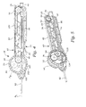
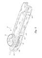
- the handle 16 generally includes an elongate stationary member 60 defined by two shells portions 62, 64, an internal longitudinally movable member 66, and a pair of manually rotatable wheel-like knobs 68, 70 which effect movement of the movable member 66 relative to the stationary member 60, as described in more detail below.
- the exterior of the stationary member 60 is preferably ergonomically shaped to fit in the palm of either a left or right hand of an operator and includes a lower grip 72 permitting a pointer finger of the hand of the operator to secure the handle in the palm of the hand.
- the interior of the stationary member defines an axial track 74 and a rear opening 76.
- the movable member 66 has a preferably substantially cruciate cross-sectional shape, with lateral portions 78, 80 residing in the track defined by the shell portions 62, 64 of the stationary member 60.
- An upper portion 82 of the movable member 66 defines a toothed slot 84, and an axial throughbore 86 is provided through a central portion of the movable member.
- the stiff tubular portion 38 at the proximal end of the inner tubular member 12 extends through the axial throughbore 86, and a portion of the luer connection 76 is coupled in a pocket 88 ( Fig. 5 ) at the rear end of the stationary member 60 such that the luer connection extends from the rear of the stationary member.
- the inner tubular member 12 is longitudinally fixed relative to the handle 16, and the stiff tubular portion 38 provides very high longitudinal stiffness at the proximal end of the inner tubular member.
- the outer jacket 14 has a proximal end 90 which is fixedly coupled in the axial throughbore 86 of the movable member 66.
- the outer jacket 14 moves relative to the stationary member 60 of the handle 16.
- a strain relief sleeve 92 is fixed to the stationary member 60 and extends distally from the stationary member.
- the outer jacket 14 is therefore likewise movable relative to the strain relief sleeve 92.
- the stationary member 60 is provided at its distal end with a first rotating sprocket 94, and a gear 96 coupled to the first sprocket 94, and at its proximal end with a second rotating sprocket 98.
- a toothed belt 100 extends around the first and second sprockets 94, 98.
- a portion of the belt is provided in the toothed slot 84 of the movable member 66 to thereby lock the movable member to the belt.
- rotation of the gear 96 causes movement of the belt, which results in movement of the moveable member 66 and movement of the outer jacket 14 relative to the handle 16 and the inner tubular member 12.
- the knobs 68, 70 are provided one of each side of the stationary member 60 and connected together with a screw (not shown).
- the knobs 68, 70 are rotatable relative to the stationary member 60, preferably with the axis of rotation A R being vertically offset above the longitudinal axis A L of the stent delivery system 10. Due to the offset of the axis of rotation A R relative to the longitudinal axis A L , the knobs 68, 70 can be kept to a comfortable relatively small size while permitting an upper portion of each knob to rise above the top of the stationary member of the handle. As a result, when the handle 16 is held in either the left or right hand of the physician, the thumb of that hand is situated for placement on one of the knobs.
- knob 70 includes a peripheral portion 102 provided with inwardly-directed gear teeth 104 that engage the gear 96, and a knob cover 106.
- the circumference of the peripheral portion 102 of each knob is preferably entirely exposed (i.e., located outside the stationary member 60) and provided with a friction-enhancing material such as rubber in which is provided a finger engagement structure, such as grooves 106, ribs, or knurls.
- the respective knob 68, 70 may then be easily rotated by movement of the physician's thumb to effect retraction of the jacket 14 from over the inner tubular member 12.
- the instrument is adapted for single-handed operation by either hand of the physician.
- each knob is formed with a raised substantially diametric grip 108 and includes contours 110 adapted to receive a distal portion of thumb to provide leverage in turning the knob.
- This structure also implicitly identifies the direction of knob rotation for jacket retraction.
- each knob is preferably provided with arrows 112 which explicitly indicate the direction of required rotation.
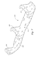
- a cradle 200 is provided.
- the cradle 200 includes supports 202, 204, 206 which are adapted to stably hold the handle 16 on its side.
- one knob 68 of the handle is received in a space 208, and the other knob 70 faces upward.
- Knob 68 is positioned in the space 208 such that it freely rotates when knob 70 is manually rotated.
- the bottom surface 210 of the cradle 200 may be coupled to a platform, e.g., with double-sided adhesive tape.
- the handle can be adapted with sprockets and gears having different sizes and different numbers of gear teeth, and knobs of different diameters.
- the motion by the operator's hand and corresponding motion of the distal components of the delivery system is adjustable so that the delivery instrument is optimized for each length of stent.
- the same amount of hand motion by the operator may be translated into relatively less motion in a delivery instrument on which a short stent is loaded, and translated into relatively more motion in a delivery instrument on which a longer stent is loaded.
- a common rotational movement may be utilized to deploy stents of any length.
- a gear system may be employed with a suitable operator-engageable extra step-down gear that permits the operator to choose between gear ratios that provide enhanced control for short or longer stents.
- a stiffly resilient element e.g., a metal leaf spring 114 ( Fig. 5 ) is also provided in the stationary member 60 and has an end 115 which is in contact with the first sprocket 94.
- the teeth thereof successively contact the resilient element and produce an audible clicking sound, providing feedback to the physician or other operator that the rotation of the knobs is causing operation of a mechanism at the interior of the handle.
- the location of the spring 114 relative to the first sprocket 94 prevents rotation of the handles in a direction which would cause movement of the outer jacket distally over the inner tubular member.
- the operator is prevented from attempting to retract the stent back into the outer jacket, as most self-expanding stent designs do not allow such retraction, and the stent would be damaged thereby.
- the proximal portion of the outer jacket is provided with incremental or quantitative visual indicia 116 ( Fig. 6 ).
- the visual indicia preferably correspond to the length of the stent being deployed. As such, as the outer jacket 14 is retracted from over the inner tubular member 12 and into the strain relief handle, the indicia can be seen to move relative to the strain relief sleeve 92, and the operator can determine from inspection at the proximal end of the instrument how much of the stent remains to be deployed.
- the visual indicia may extend only the length of the stent loaded in the system, or may extend the maximum length of any stent which may be loaded on the system, and include discrete markings to indicate the jacket retraction required for deployment of stents of various lengths, e.g., markings at 15 mom, 30 mom, 60 mm, and 90 mm.
- the proximal end of the outer jacket may be provided with relief 118, either recessed beneath the surface (as shown) or protruding from the surface, so that the operator may also determine the degree of deployment by tactile feel.
- the tactile indicia may be coincident or independent of the visual indicia.
- knob 68 and the stationary member 60 of the handle 16 each include a keyhole which preferably extends parallel to the axis of rotation A R of the knobs 68, 70 ( Fig. 4 ).
- the keyhole 150 in the knob 68 includes a slot 152 which is preferably oriented substantially transverse to a slot (not shown) in the stationary member 60; i.e., the slot in the stationary member 60 is in the same orientation as the crossbar 154 on the shaft 158 of the key 156 shown in Fig. 10 .
- the key 156 prevents inadvertent partial or full deployment of the stent while the key is in place; i.e., during shipping and storage of the stent-loaded instrument.
- the key 150 can be turned and withdrawn ( Fig. 10 ).
- Other suitable locking mechanisms can also be used.
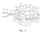
- a lower side of the stationary member 60 is provided with an opening 160, and knob 68 includes a notch 162 which when aligned adjacent the opening 160 defines a channel 164 for receiving a spring clip 166.
- a spring clip 166 includes a resilient U-shaped portion 168 having a barb 170 along one side thereof, and a handle 172 permitting the U-shaped portion 168 to be manually reduced in dimension.
- the U-shaped portion 168 can be placed in the channel 164 with the U-shaped portion 168 being compressed as the barb 170 contacts the area about the opening 160.
- the U-shaped portion 168 springs back to shape once in the stationary member 60, as the barb 170 seats in the notch 162 ( Fig. 12 ).
- the barb 170 interferes with rotation of the knob 68, and thus locks the knobs 68, 70 relative to the stationary member 60.
- the clip handle 172 is compressed and the clip 166 is removed.
- the delivery instrument In use, with the locking system unlocked, and the distal end of the inner tubular member is fed over a guidewire and guided therealong to the deployment site. The distal end of the delivery instrument is then fluoroscopically viewed to ascertain that the instrument is in a predeployment configuration. That is, the delivery instrument is optimized for use with self-expanding stents having a plurality of radiopaque markers 120, 122 at each of its ends, and the ends of the stent are seen to be situated proximal of both the radiopaque tip 34 of the inner tubular member 12 and the radiopaque marker 58 at the distal end of the outer jacket 14 ( Fig. 3 ).
- knobs 68, 70 on the handle 16 is/are then manually rotated relative to the handle to cause retraction of the outer jacket 14.
- the handle preferably provides audible, tactile, and visual indications of the retraction.
- the marker 58 on the jacket 14 is seen to move proximally toward and past the distal stent markers 120.
- the distal stent markers 120 are seen to separate radially as the stent 28 self-expands.
- the clamping force created by clamping the proximal end of the stent between the protruding ring 32 on the inner tubular member 12 and the interior of the outer jacket 14
- the stent 28 is completely released, the markers 120, 122 at both ends of the stent are seen to be expanded radially, and the marker 58 on the outer jacket is positioned proximal to the markers 122 on the proximal end of the stent.
- the stent delivery system provides greater control over stent deployment via one or more visual and auditory feedback at the proximal end of the instrument, increased control of the relative movement of the outer jacket relative to the inner tubular member, and prevention of premature release of the stent from the deployment instrument.
Landscapes
- Health & Medical Sciences (AREA)
- Engineering & Computer Science (AREA)
- Biomedical Technology (AREA)
- Cardiology (AREA)
- Oral & Maxillofacial Surgery (AREA)
- Transplantation (AREA)
- Heart & Thoracic Surgery (AREA)
- Vascular Medicine (AREA)
- Life Sciences & Earth Sciences (AREA)
- Animal Behavior & Ethology (AREA)
- General Health & Medical Sciences (AREA)
- Public Health (AREA)
- Veterinary Medicine (AREA)
- Media Introduction/Drainage Providing Device (AREA)
Applications Claiming Priority (2)
| Application Number | Priority Date | Filing Date | Title |
|---|---|---|---|
| US10/189,993 US20040006380A1 (en) | 2002-07-05 | 2002-07-05 | Stent delivery system |
| EP03762619.9A EP1519697B1 (de) | 2002-07-05 | 2003-07-04 | Stent-ablagesystem |
Related Parent Applications (3)
| Application Number | Title | Priority Date | Filing Date |
|---|---|---|---|
| EP03762619.9 Division | 2003-07-04 | ||
| EP03762619.9A Division-Into EP1519697B1 (de) | 2002-07-05 | 2003-07-04 | Stent-ablagesystem |
| EP03762619.9A Division EP1519697B1 (de) | 2002-07-05 | 2003-07-04 | Stent-ablagesystem |
Publications (3)
| Publication Number | Publication Date |
|---|---|
| EP2260794A2 true EP2260794A2 (de) | 2010-12-15 |
| EP2260794A3 EP2260794A3 (de) | 2014-03-19 |
| EP2260794B1 EP2260794B1 (de) | 2016-12-21 |
Family
ID=29999769
Family Applications (2)
| Application Number | Title | Priority Date | Filing Date |
|---|---|---|---|
| EP10181967.0A Expired - Lifetime EP2260794B1 (de) | 2002-07-05 | 2003-07-04 | Stenteinbringungssystem |
| EP03762619.9A Expired - Lifetime EP1519697B1 (de) | 2002-07-05 | 2003-07-04 | Stent-ablagesystem |
Family Applications After (1)
| Application Number | Title | Priority Date | Filing Date |
|---|---|---|---|
| EP03762619.9A Expired - Lifetime EP1519697B1 (de) | 2002-07-05 | 2003-07-04 | Stent-ablagesystem |
Country Status (6)
| Country | Link |
|---|---|
| US (1) | US20040006380A1 (de) |
| EP (2) | EP2260794B1 (de) |
| JP (2) | JP2005532100A (de) |
| AU (1) | AU2003260304A1 (de) |
| CA (1) | CA2489382C (de) |
| WO (1) | WO2004004597A2 (de) |
Families Citing this family (120)
| Publication number | Priority date | Publication date | Assignee | Title |
|---|---|---|---|---|
| US6254564B1 (en) | 1998-09-10 | 2001-07-03 | Percardia, Inc. | Left ventricular conduit with blood vessel graft |
| DE10010074B4 (de) | 2000-02-28 | 2005-04-14 | Fraunhofer-Gesellschaft zur Förderung der angewandten Forschung e.V. | Vorrichtung zur Befestigung und Verankerung von Herzklappenprothesen |
| DE10010073B4 (de) * | 2000-02-28 | 2005-12-22 | Fraunhofer-Gesellschaft zur Förderung der angewandten Forschung e.V. | Verankerung für implantierbare Herzklappenprothesen |
| US20050021123A1 (en) * | 2001-04-30 | 2005-01-27 | Jurgen Dorn | Variable speed self-expanding stent delivery system and luer locking connector |
| WO2003003944A2 (en) | 2001-07-06 | 2003-01-16 | Angiomed Gmbh & Co. Medizintechnik Kg | Delivery system having a rapid pusher assembly for self-expanding stent, and stent exchange configuration |
| FR2828263B1 (fr) | 2001-08-03 | 2007-05-11 | Philipp Bonhoeffer | Dispositif d'implantation d'un implant et procede d'implantation du dispositif |
| GB0123633D0 (en) | 2001-10-02 | 2001-11-21 | Angiomed Ag | Stent delivery system |
| US20040006380A1 (en) | 2002-07-05 | 2004-01-08 | Buck Jerrick C. | Stent delivery system |
| US20040093056A1 (en) * | 2002-10-26 | 2004-05-13 | Johnson Lianw M. | Medical appliance delivery apparatus and method of use |
| US8568467B2 (en) | 2003-01-15 | 2013-10-29 | Angiomed Gmbh & Co. Medizintechnik Kg | Trans-luminal surgical device |
| ITTO20030037A1 (it) | 2003-01-24 | 2004-07-25 | Sorin Biomedica Cardio S P A Ora S Orin Biomedica | Dispositivo d'azionamento per cateteri. |
| JP2006518625A (ja) * | 2003-02-14 | 2006-08-17 | サルヴィアック・リミテッド | ステントデリバリ及び配置システム |
| WO2004075789A2 (en) | 2003-02-26 | 2004-09-10 | Cook Incorporated | PROTHESIS ADAPTED FOR PLACEDd UNDER EXTERNAL IMAGING |
| US7637934B2 (en) * | 2003-03-31 | 2009-12-29 | Merit Medical Systems, Inc. | Medical appliance optical delivery and deployment apparatus and method |
| US7780716B2 (en) * | 2003-09-02 | 2010-08-24 | Abbott Laboratories | Delivery system for a medical device |
| US7794489B2 (en) * | 2003-09-02 | 2010-09-14 | Abbott Laboratories | Delivery system for a medical device |
| JP4713478B2 (ja) * | 2003-09-02 | 2011-06-29 | アボット・ラボラトリーズ | 医療器具の送出システム |
| US7967829B2 (en) * | 2003-10-09 | 2011-06-28 | Boston Scientific Scimed, Inc. | Medical device delivery system |
| US20050256562A1 (en) * | 2004-05-14 | 2005-11-17 | Boston Scientific Scimed, Inc. | Stent delivery handle and assembly formed therewith |
| US20050273151A1 (en) * | 2004-06-04 | 2005-12-08 | John Fulkerson | Stent delivery system |
| US7303580B2 (en) * | 2004-07-26 | 2007-12-04 | Cook Incorporated | Stent delivery system allowing controlled release of a stent |
| DE102005003632A1 (de) | 2005-01-20 | 2006-08-17 | Fraunhofer-Gesellschaft zur Förderung der angewandten Forschung e.V. | Katheter für die transvaskuläre Implantation von Herzklappenprothesen |
| EP1872741B1 (de) | 2005-03-28 | 2018-12-05 | Terumo Kabushiki Kaisha | Instrument zur aufweitung eines körperorgans |
| JP4890065B2 (ja) * | 2005-03-29 | 2012-03-07 | テルモ株式会社 | 生体器官拡張器具 |
| BRPI0610519A2 (pt) * | 2005-04-05 | 2010-06-22 | Elixir Medical Corp | estrutura degradável, e, implante degradável |
| WO2007004076A2 (en) | 2005-05-09 | 2007-01-11 | Angiomed Gmbh & Co. Medizintechnik Kg | Implant delevery device |
| WO2007005799A1 (en) * | 2005-06-30 | 2007-01-11 | Abbott Laboratories | Delivery system for a medical device |
| DE602006012687D1 (de) * | 2005-08-17 | 2010-04-15 | Bard Inc C R | Stentabgabesystem mit variabler geschwindigkeit |
| US8968379B2 (en) * | 2005-09-02 | 2015-03-03 | Medtronic Vascular, Inc. | Stent delivery system with multiple evenly spaced pullwires |
| EP1933778B1 (de) | 2005-10-14 | 2010-01-06 | Gore Enterprise Holdings, Inc. | Vorrichtung zur ablage eines implantierbaren medizinprodukts |
| DE102005051849B4 (de) | 2005-10-28 | 2010-01-21 | JenaValve Technology Inc., Wilmington | Vorrichtung zur Implantation und Befestigung von Herzklappenprothesen |
| DE102005052628B4 (de) * | 2005-11-04 | 2014-06-05 | Jenavalve Technology Inc. | Selbstexpandierendes, flexibles Drahtgeflecht mit integrierter Klappenprothese für den transvaskulären Herzklappenersatz und ein System mit einer solchen Vorrichtung und einem Einführkatheter |
| US20070118079A1 (en) * | 2005-11-21 | 2007-05-24 | Moberg John R | Medical devices and related systems and methods |
| US20070213813A1 (en) * | 2005-12-22 | 2007-09-13 | Symetis Sa | Stent-valves for valve replacement and associated methods and systems for surgery |
| US20070156224A1 (en) * | 2006-01-04 | 2007-07-05 | Iulian Cioanta | Handle system for deploying a prosthetic implant |
| US11026822B2 (en) | 2006-01-13 | 2021-06-08 | C. R. Bard, Inc. | Stent delivery system |
| JP5345856B2 (ja) | 2006-01-13 | 2013-11-20 | シー・アール・バード・インコーポレーテッド | ステント搬送システム |
| US20070219617A1 (en) * | 2006-03-17 | 2007-09-20 | Sean Saint | Handle for Long Self Expanding Stent |
| USD578216S1 (en) | 2006-06-12 | 2008-10-07 | Angiomed Gmby & Co. Medizintechnik Kg | Handle for a medical delivery device |
| USD598543S1 (en) | 2006-06-13 | 2009-08-18 | Angiomed Gmbh & Co. Medizintechnik Kg | Handle for a medical delivery device |
| GB0615658D0 (en) | 2006-08-07 | 2006-09-13 | Angiomed Ag | Hand-held actuator device |
| GB0618516D0 (en) * | 2006-09-20 | 2006-11-01 | Angiomed Ag | Hand-held actuator device |
| JP2008132027A (ja) * | 2006-11-27 | 2008-06-12 | Piolax Medical Device:Kk | 管状器官治療具の搬送装置 |
| US9138315B2 (en) | 2007-04-13 | 2015-09-22 | Jenavalve Technology Gmbh | Medical device for treating a heart valve insufficiency or stenosis |
| US7896915B2 (en) * | 2007-04-13 | 2011-03-01 | Jenavalve Technology, Inc. | Medical device for treating a heart valve insufficiency |
| EP2659861B1 (de) * | 2007-05-15 | 2019-03-13 | JenaValve Technology, Inc. | Griff zur Manipulation einer Katheterspitze, Kathetersystem und medizinisches Einführsystem zum Einführen eines selbstexpandierbaren Herzklappenstents |
| USD576725S1 (en) | 2007-06-20 | 2008-09-09 | Abbot Laboratories, Inc. | Medical device delivery handle |
| USD578644S1 (en) | 2007-06-20 | 2008-10-14 | Abbott Laboratories | Medical device delivery handle |
| USD578645S1 (en) | 2007-06-20 | 2008-10-14 | Abbott Laboratories | Medical device delivery handle |
| USD578643S1 (en) | 2007-06-20 | 2008-10-14 | Abbott Laboratories | Medical device delivery handle |
| FR2917601B1 (fr) * | 2007-06-25 | 2010-03-19 | Stentys S A S | Dispositif de commande d'un catheter |
| GB0713497D0 (en) | 2007-07-11 | 2007-08-22 | Angiomed Ag | Device for catheter sheath retraction |
| US9149379B2 (en) * | 2007-07-16 | 2015-10-06 | Cook Medical Technologies Llc | Delivery device |
| US8092468B2 (en) * | 2007-12-26 | 2012-01-10 | Cook Medical Technologies Llc | Deployment handle for an implant deployment device |
| US20090210046A1 (en) * | 2008-02-20 | 2009-08-20 | Abbott Laboratories | Handle assembly for a delivery system |
| US9168130B2 (en) | 2008-02-26 | 2015-10-27 | Jenavalve Technology Gmbh | Stent for the positioning and anchoring of a valvular prosthesis in an implantation site in the heart of a patient |
| US8465540B2 (en) * | 2008-02-26 | 2013-06-18 | Jenavalve Technology, Inc. | Stent for the positioning and anchoring of a valvular prosthesis |
| WO2011104269A1 (en) | 2008-02-26 | 2011-09-01 | Jenavalve Technology Inc. | Stent for the positioning and anchoring of a valvular prosthesis in an implantation site in the heart of a patient |
| US8317858B2 (en) * | 2008-02-26 | 2012-11-27 | Jenavalve Technology, Inc. | Stent for the positioning and anchoring of a valvular prosthesis in an implantation site in the heart of a patient |
| US8398704B2 (en) | 2008-02-26 | 2013-03-19 | Jenavalve Technology, Inc. | Stent for the positioning and anchoring of a valvular prosthesis in an implantation site in the heart of a patient |
| US9044318B2 (en) | 2008-02-26 | 2015-06-02 | Jenavalve Technology Gmbh | Stent for the positioning and anchoring of a valvular prosthesis |
| US9750625B2 (en) | 2008-06-11 | 2017-09-05 | C.R. Bard, Inc. | Catheter delivery device |
| GB0810749D0 (en) | 2008-06-11 | 2008-07-16 | Angiomed Ag | Catherter delivery device |
| EP2520320B1 (de) | 2008-07-01 | 2016-11-02 | Endologix, Inc. | Kathetersystem |
| US7976574B2 (en) * | 2008-08-08 | 2011-07-12 | Advanced Cardiovascular Systems, Inc. | Delivery system with variable delivery rate for deploying a medical device |
| WO2010078352A1 (en) * | 2008-12-30 | 2010-07-08 | Wilson-Cook Medical Inc. | Delivery device |
| US20100292779A1 (en) * | 2009-05-15 | 2010-11-18 | Helmut Straubinger | Device for compressing a stent and a system as well as a method for loading a stent into a medical delivery system |
| JP2013500792A (ja) * | 2009-07-30 | 2013-01-10 | ストライカー コーポレイション | ステントデリバリーシステム |
| US8986363B2 (en) * | 2009-12-30 | 2015-03-24 | Cook Medical Technologies Llc | Proximal release delivery system |
| US8778007B2 (en) * | 2010-01-25 | 2014-07-15 | Empirilon Technology, Llc | Systems for performing intralumenal reconstruction |
| WO2011094527A1 (en) * | 2010-01-29 | 2011-08-04 | Cook Medical Technologies Llc | Mechanically expandable delivery and dilation systems |
| US10856978B2 (en) | 2010-05-20 | 2020-12-08 | Jenavalve Technology, Inc. | Catheter system |
| US11278406B2 (en) | 2010-05-20 | 2022-03-22 | Jenavalve Technology, Inc. | Catheter system for introducing an expandable heart valve stent into the body of a patient, insertion system with a catheter system and medical device for treatment of a heart valve defect |
| WO2011147849A1 (en) | 2010-05-25 | 2011-12-01 | Jenavalve Technology Inc. | Prosthetic heart valve and transcatheter delivered endoprosthesis comprising a prosthetic heart valve and a stent |
| CA2806234C (en) | 2010-07-30 | 2015-03-24 | Cook Medical Technologies Llc | Controlled release and recapture prosthetic deployment device |
| EP2428189A1 (de) | 2010-09-10 | 2012-03-14 | Symetis Sa | Kathetereinbringungssystem für ein Stentventil |
| GB201017834D0 (en) | 2010-10-21 | 2010-12-01 | Angiomed Ag | System to deliver a bodily implant |
| JP6081918B2 (ja) * | 2010-11-17 | 2017-02-15 | ボストン サイエンティフィック サイムド,インコーポレイテッドBoston Scientific Scimed,Inc. | ステント送達システム、ステント送達システムのサムホイールの意図されない作動を防止するためのロック部材および防止する方法 |
| CN103561807B (zh) | 2011-03-01 | 2015-11-25 | 恩朵罗杰克斯股份有限公司 | 导管系统及其使用方法 |
| WO2012166467A1 (en) | 2011-05-27 | 2012-12-06 | Stryker Corporation | Assembly for percutaneously inserting an implantable medical device, steering the device to a target location and deploying the device |
| US8734500B2 (en) * | 2011-09-27 | 2014-05-27 | DePuy Synthes Products, LLC | Distal detachment mechanisms for vascular devices |
| USD678512S1 (en) | 2011-09-29 | 2013-03-19 | Medline Industries, Inc. | Suction handle |
| CN104159543B (zh) | 2011-10-21 | 2016-10-12 | 耶拿阀门科技公司 | 用于将可扩张心脏瓣膜支架引入患者体内的导管系统 |
| WO2013120082A1 (en) | 2012-02-10 | 2013-08-15 | Kassab Ghassan S | Methods and uses of biological tissues for various stent and other medical applications |
| WO2013121811A1 (ja) * | 2012-02-15 | 2013-08-22 | テルモ株式会社 | ステントデリバリーシステム |
| US9662235B2 (en) * | 2012-04-04 | 2017-05-30 | Boston Scientific Scimed, Inc. | Handle for delivering medical device |
| US10376362B2 (en) | 2012-04-05 | 2019-08-13 | Medtronic Vascular Galway | Valve introducers with adjustable deployment mechanism and implantation depth gauge |
| JP6227632B2 (ja) | 2012-05-16 | 2017-11-08 | イェーナヴァルヴ テクノロジー ゲゼルシャフト ミット ベシュレンクテル ハフツング | 拡張可能心臓代用弁を導入するためのカテーテル送達システムおよび心臓弁欠陥の治療のための医療デバイス |
| US9233015B2 (en) | 2012-06-15 | 2016-01-12 | Trivascular, Inc. | Endovascular delivery system with an improved radiopaque marker scheme |
| US9089321B2 (en) * | 2012-10-15 | 2015-07-28 | Biomet Sports Medicine, Llc | Wheeled suture passer |
| ES2931210T3 (es) * | 2012-11-21 | 2022-12-27 | Edwards Lifesciences Corp | Mecanismos de retención para válvulas cardiacas protésicas |
| EP4215163A1 (de) | 2013-02-11 | 2023-07-26 | Cook Medical Technologies LLC | Expandierbarer stützrahmen und medizinische vorrichtung |
| US9308108B2 (en) | 2013-03-13 | 2016-04-12 | Cook Medical Technologies Llc | Controlled release and recapture stent-deployment device |
| US9827121B2 (en) * | 2013-03-15 | 2017-11-28 | Cook Medical Technologies Llc | Quick release deployment handle for medical devices |
| WO2015012007A1 (ja) * | 2013-07-22 | 2015-01-29 | テルモ株式会社 | ステントデリバリーシステム |
| US9974676B2 (en) | 2013-08-09 | 2018-05-22 | Cook Medical Technologies Llc | Wire collection device with geared advantage |
| US9974677B2 (en) | 2013-08-20 | 2018-05-22 | Cook Medical Technologies Llc | Wire collection device for stent delivery system |
| WO2015028209A1 (en) | 2013-08-30 | 2015-03-05 | Jenavalve Technology Gmbh | Radially collapsible frame for a prosthetic valve and method for manufacturing such a frame |
| US9974678B2 (en) | 2014-03-10 | 2018-05-22 | Cook Medical Technologies Llc | Wire collection device with varying collection diameter |
| US9884143B2 (en) | 2014-05-30 | 2018-02-06 | Medline Industries, Inc. | Medical personal-services suction handle |
| USD749717S1 (en) | 2014-05-30 | 2016-02-16 | Medline Industries, Inc. | Suction handle |
| USD919804S1 (en) | 2014-10-13 | 2021-05-18 | W. L. Gore & Associates, Inc. | Handle for medical delivery apparatus device |
| US10292850B2 (en) * | 2014-11-04 | 2019-05-21 | Cook Medical Technologies Llc | Deployment handle for a prosthesis delivery device |
| US10849773B2 (en) * | 2014-11-10 | 2020-12-01 | Cook Medical Technologies Llc | Stent delivery device |
| US10327899B2 (en) | 2015-03-13 | 2019-06-25 | Medtronic Vascular, Inc. | Delivery device for prosthetic heart valve with capsule adjustment device |
| US10758349B2 (en) | 2015-03-13 | 2020-09-01 | Medtronic Vascular, Inc. | Delivery device for prosthetic heart valve with capsule adjustment device |
| US11504236B2 (en) | 2015-03-13 | 2022-11-22 | Medtronic Vascular, Inc. | Delivery device for prosthetic heart valve with capsule adjustment device |
| EP3270825B1 (de) | 2015-03-20 | 2020-04-22 | JenaValve Technology, Inc. | Herzklappenprothesenzuführsystem |
| EP3288495B1 (de) | 2015-05-01 | 2019-09-25 | JenaValve Technology, Inc. | Vorrichtung mit reduzierter herzschrittmacherrate bei herzklappenersatz |
| CN111529126A (zh) | 2015-06-30 | 2020-08-14 | 恩朵罗杰克斯股份有限公司 | 用于将第一细长构件固定至第二细长构件的系统及方法 |
| WO2017195125A1 (en) | 2016-05-13 | 2017-11-16 | Jenavalve Technology, Inc. | Heart valve prosthesis delivery system and method for delivery of heart valve prosthesis with introducer sheath and loading system |
| US10076428B2 (en) * | 2016-08-25 | 2018-09-18 | DePuy Synthes Products, Inc. | Expansion ring for a braided stent |
| US11197754B2 (en) | 2017-01-27 | 2021-12-14 | Jenavalve Technology, Inc. | Heart valve mimicry |
| US11517458B2 (en) * | 2018-04-05 | 2022-12-06 | Microvention, Inc. | Implant delivery system |
| US10441449B1 (en) * | 2018-05-30 | 2019-10-15 | Vesper Medical, Inc. | Rotary handle stent delivery system and method |
| US10449073B1 (en) | 2018-09-18 | 2019-10-22 | Vesper Medical, Inc. | Rotary handle stent delivery system and method |
| US11219541B2 (en) | 2020-05-21 | 2022-01-11 | Vesper Medical, Inc. | Wheel lock for thumbwheel actuated device |
| DE102021132089A1 (de) | 2021-12-06 | 2023-06-07 | Optimed Medizinische Instrumente Gmbh | Handeinheit zum Zuführen und Freigeben eines Implantats |
| CN118450867A (zh) * | 2021-12-08 | 2024-08-06 | 丝路医疗公司 | 用于腔内假体的输送系统和使用方法 |
| US12171658B2 (en) | 2022-11-09 | 2024-12-24 | Jenavalve Technology, Inc. | Catheter system for sequential deployment of an expandable implant |
Citations (1)
| Publication number | Priority date | Publication date | Assignee | Title |
|---|---|---|---|---|
| WO2004004597A2 (en) | 2002-07-05 | 2004-01-15 | Edwards Lifesciences Ag | Stent delivery system |
Family Cites Families (41)
| Publication number | Priority date | Publication date | Assignee | Title |
|---|---|---|---|---|
| US4665918A (en) * | 1986-01-06 | 1987-05-19 | Garza Gilbert A | Prosthesis system and method |
| CA2060067A1 (en) * | 1991-01-28 | 1992-07-29 | Lilip Lau | Stent delivery system |
| US5628783A (en) * | 1991-04-11 | 1997-05-13 | Endovascular Technologies, Inc. | Bifurcated multicapsule intraluminal grafting system and method |
| JPH0515904U (ja) * | 1991-08-14 | 1993-03-02 | オリンパス光学工業株式会社 | 内視鏡用拡張具 |
| ES2109969T3 (es) * | 1991-10-11 | 1998-02-01 | Angiomed Ag | Procedimiento para la dilatacion de una estenosis. |
| US5707376A (en) * | 1992-08-06 | 1998-01-13 | William Cook Europe A/S | Stent introducer and method of use |
| EP0596145B1 (de) * | 1992-10-31 | 1996-05-08 | Schneider (Europe) Ag | Anordnung zum Implantieren von selbstexpandierenden Endoprothesen |
| EP0702535B1 (de) * | 1993-04-13 | 2003-01-08 | Boston Scientific Corporation | Vorrichtung zum anbringen einer prothese mit einer dilatationsspitze |
| US5603801A (en) * | 1993-04-30 | 1997-02-18 | Defriese; John M. | Infinite universal sealing assembly |
| FR2710833B1 (fr) * | 1993-10-05 | 1995-11-24 | Celsa Lg | Dispositif d'implantation d'une prothèse médicale dans un conduit d'un corps humain ou animal et procédé de centrage d'un tel dispositif. |
| US5507769A (en) * | 1994-10-18 | 1996-04-16 | Stentco, Inc. | Method and apparatus for forming an endoluminal bifurcated graft |
| US5417708A (en) * | 1994-03-09 | 1995-05-23 | Cook Incorporated | Intravascular treatment system and percutaneous release mechanism therefor |
| US5415664A (en) * | 1994-03-30 | 1995-05-16 | Corvita Corporation | Method and apparatus for introducing a stent or a stent-graft |
| US5683451A (en) * | 1994-06-08 | 1997-11-04 | Cardiovascular Concepts, Inc. | Apparatus and methods for deployment release of intraluminal prostheses |
| JP3130318B2 (ja) * | 1994-10-27 | 2001-01-31 | シュナイダー(ユーエスエー)インク | ステント送り出し器具 |
| DK175166B1 (da) * | 1995-01-03 | 2004-06-21 | Cook William Europ | Fremgangsmåde til fremstilling af et aggregat til placering af en embolisationscoil i det vaskulære system og et sådant aggregat samt et apparat til fremføring af aggregatet |
| US5788707A (en) * | 1995-06-07 | 1998-08-04 | Scimed Life Systems, Inc. | Pull back sleeve system with compression resistant inner shaft |
| US5702418A (en) * | 1995-09-12 | 1997-12-30 | Boston Scientific Corporation | Stent delivery system |
| US5591195A (en) * | 1995-10-30 | 1997-01-07 | Taheri; Syde | Apparatus and method for engrafting a blood vessel |
| US5800517A (en) * | 1996-08-19 | 1998-09-01 | Scimed Life Systems, Inc. | Stent delivery system with storage sleeve |
| US5860998A (en) * | 1996-11-25 | 1999-01-19 | C. R. Bard, Inc. | Deployment device for tubular expandable prosthesis |
| US5968052A (en) * | 1996-11-27 | 1999-10-19 | Scimed Life Systems Inc. | Pull back stent delivery system with pistol grip retraction handle |
| US6165166A (en) * | 1997-04-25 | 2000-12-26 | Schneider (Usa) Inc. | Trilayer, extruded medical tubing and medical devices incorporating such tubing |
| US5906619A (en) * | 1997-07-24 | 1999-05-25 | Medtronic, Inc. | Disposable delivery device for endoluminal prostheses |
| DE29717110U1 (de) * | 1997-09-24 | 1997-11-13 | Optimed Medizinische Instrumente GmbH, 76275 Ettlingen | Vorrichtung zum Einführen eines Stents, eines Drainagerohrs o.dgl. in Hohlorgane |
| US6280467B1 (en) * | 1998-02-26 | 2001-08-28 | World Medical Manufacturing Corporation | Delivery system for deployment and endovascular assembly of a multi-stage stented graft |
| US6019778A (en) * | 1998-03-13 | 2000-02-01 | Cordis Corporation | Delivery apparatus for a self-expanding stent |
| AU3342399A (en) * | 1998-03-31 | 1999-10-18 | Salviac Limited | A delivery catheter |
| US6264689B1 (en) * | 1998-03-31 | 2001-07-24 | Scimed Life Systems, Incorporated | Low profile medical stent |
| US5944727A (en) * | 1998-09-02 | 1999-08-31 | Datascope Investment Corp. | Stent/graft catheter handle |
| US6730116B1 (en) * | 1999-04-16 | 2004-05-04 | Medtronic, Inc. | Medical device for intraluminal endovascular stenting |
| US6726712B1 (en) * | 1999-05-14 | 2004-04-27 | Boston Scientific Scimed | Prosthesis deployment device with translucent distal end |
| EP1180003B1 (de) * | 1999-05-20 | 2008-01-16 | Boston Scientific Limited | Stenteinbringungssystem mit innenliegendem Stabilisator |
| US6241758B1 (en) * | 1999-05-28 | 2001-06-05 | Advanced Cardiovascular Systems, Inc. | Self-expanding stent delivery system and method of use |
| US6613075B1 (en) * | 1999-10-27 | 2003-09-02 | Cordis Corporation | Rapid exchange self-expanding stent delivery catheter system |
| US6602280B2 (en) * | 2000-02-02 | 2003-08-05 | Trivascular, Inc. | Delivery system and method for expandable intracorporeal device |
| US6716190B1 (en) * | 2000-04-19 | 2004-04-06 | Scimed Life Systems, Inc. | Device and methods for the delivery and injection of therapeutic and diagnostic agents to a target site within a body |
| US6527779B1 (en) * | 2000-07-10 | 2003-03-04 | Endotex Interventional Systems, Inc. | Stent delivery device |
| GB0114939D0 (en) * | 2001-06-19 | 2001-08-08 | Angiomed Ag | Luer connector portion |
| US6645238B2 (en) * | 2001-07-09 | 2003-11-11 | Scimed Life Systems, Inc. | Skids stent delivery system |
| US6866669B2 (en) * | 2001-10-12 | 2005-03-15 | Cordis Corporation | Locking handle deployment mechanism for medical device and method |
-
2002
- 2002-07-05 US US10/189,993 patent/US20040006380A1/en not_active Abandoned
-
2003
- 2003-07-04 CA CA2489382A patent/CA2489382C/en not_active Expired - Lifetime
- 2003-07-04 WO PCT/EP2003/007169 patent/WO2004004597A2/en not_active Ceased
- 2003-07-04 AU AU2003260304A patent/AU2003260304A1/en not_active Abandoned
- 2003-07-04 JP JP2004518703A patent/JP2005532100A/ja active Pending
- 2003-07-04 EP EP10181967.0A patent/EP2260794B1/de not_active Expired - Lifetime
- 2003-07-04 EP EP03762619.9A patent/EP1519697B1/de not_active Expired - Lifetime
-
2011
- 2011-03-15 JP JP2011056607A patent/JP5490744B2/ja not_active Expired - Lifetime
Patent Citations (1)
| Publication number | Priority date | Publication date | Assignee | Title |
|---|---|---|---|---|
| WO2004004597A2 (en) | 2002-07-05 | 2004-01-15 | Edwards Lifesciences Ag | Stent delivery system |
Also Published As
| Publication number | Publication date |
|---|---|
| WO2004004597A2 (en) | 2004-01-15 |
| US20040006380A1 (en) | 2004-01-08 |
| EP1519697B1 (de) | 2015-11-18 |
| EP1519697A1 (de) | 2005-04-06 |
| AU2003260304A1 (en) | 2004-01-23 |
| CA2489382A1 (en) | 2004-01-15 |
| EP2260794B1 (de) | 2016-12-21 |
| CA2489382C (en) | 2012-06-05 |
| EP2260794A3 (de) | 2014-03-19 |
| JP2011147799A (ja) | 2011-08-04 |
| JP2005532100A (ja) | 2005-10-27 |
| JP5490744B2 (ja) | 2014-05-14 |
Similar Documents
| Publication | Publication Date | Title |
|---|---|---|
| EP1519697B1 (de) | Stent-ablagesystem | |
| US20050273151A1 (en) | Stent delivery system | |
| JP2008501442A5 (de) | ||
| EP1893125B1 (de) | Einzelablösungseinführvorrichtung für stent | |
| JP6510644B2 (ja) | 弁ロック機構 | |
| US8657869B2 (en) | Medical systems and related methods | |
| EP1199051B1 (de) | Stentanbringungssystem | |
| CN106456349B (zh) | 自膨胀支架输送系统 | |
| US8951297B2 (en) | Stent delivery system | |
| CN110662512B (zh) | 具有精细指轮控制和快速曲柄手柄的支架递送导管 | |
| JP2022081485A (ja) | ステント送達システム | |
| JP7490167B2 (ja) | 低速から高速の引き込みのための変換可能リビングヒンジを有するステント送達カテーテル | |
| EP3419568B1 (de) | Stenteinführungssysteme mit einem reduzierten profil |
Legal Events
| Date | Code | Title | Description |
|---|---|---|---|
| PUAI | Public reference made under article 153(3) epc to a published international application that has entered the european phase |
Free format text: ORIGINAL CODE: 0009012 |
|
| AC | Divisional application: reference to earlier application |
Ref document number: 1519697 Country of ref document: EP Kind code of ref document: P |
|
| AK | Designated contracting states |
Kind code of ref document: A2 Designated state(s): DE FR GB |
|
| RIN1 | Information on inventor provided before grant (corrected) |
Inventor name: GOTTLIEB, SAUL Inventor name: BUCK, JERRY C. Inventor name: FULKERSON, JOHN D. Inventor name: SLATER, CHARLES R. Inventor name: KRATSCH, PETER K. |
|
| RIN1 | Information on inventor provided before grant (corrected) |
Inventor name: GOTTLIEB, SAUL Inventor name: FULKERSON, JOHN D. Inventor name: SLATER, CHARLES R. Inventor name: BUCK, JERRY C. Inventor name: KRATSCH, PETER K. |
|
| RIN1 | Information on inventor provided before grant (corrected) |
Inventor name: KRATSCH, PETER K. Inventor name: SLATER, CHARLES R. Inventor name: BUCK, JERRY C. Inventor name: GOTTLIEB, SAUL Inventor name: FULKERSON, JOHN D. |
|
| PUAL | Search report despatched |
Free format text: ORIGINAL CODE: 0009013 |
|
| AK | Designated contracting states |
Kind code of ref document: A3 Designated state(s): DE FR GB |
|
| RIC1 | Information provided on ipc code assigned before grant |
Ipc: A61F 2/966 20130101AFI20140207BHEP Ipc: A61F 2/95 20130101ALI20140207BHEP |
|
| 17P | Request for examination filed |
Effective date: 20140715 |
|
| RBV | Designated contracting states (corrected) |
Designated state(s): DE FR GB |
|
| REG | Reference to a national code |
Ref country code: DE Ref legal event code: R079 Ref document number: 60349755 Country of ref document: DE Free format text: PREVIOUS MAIN CLASS: A61F0002060000 Ipc: A61F0002966000 |
|
| RIC1 | Information provided on ipc code assigned before grant |
Ipc: A61F 2/95 20130101ALI20160322BHEP Ipc: A61F 2/966 20130101AFI20160322BHEP |
|
| GRAP | Despatch of communication of intention to grant a patent |
Free format text: ORIGINAL CODE: EPIDOSNIGR1 |
|
| INTG | Intention to grant announced |
Effective date: 20160518 |
|
| GRAS | Grant fee paid |
Free format text: ORIGINAL CODE: EPIDOSNIGR3 |
|
| GRAA | (expected) grant |
Free format text: ORIGINAL CODE: 0009210 |
|
| RAP1 | Party data changed (applicant data changed or rights of an application transferred) |
Owner name: C.R. BARD, INC. |
|
| AC | Divisional application: reference to earlier application |
Ref document number: 1519697 Country of ref document: EP Kind code of ref document: P |
|
| AK | Designated contracting states |
Kind code of ref document: B1 Designated state(s): DE FR GB |
|
| REG | Reference to a national code |
Ref country code: GB Ref legal event code: FG4D |
|
| REG | Reference to a national code |
Ref country code: DE Ref legal event code: R096 Ref document number: 60349755 Country of ref document: DE |
|
| REG | Reference to a national code |
Ref country code: FR Ref legal event code: PLFP Year of fee payment: 15 |
|
| REG | Reference to a national code |
Ref country code: DE Ref legal event code: R097 Ref document number: 60349755 Country of ref document: DE |
|
| PLBE | No opposition filed within time limit |
Free format text: ORIGINAL CODE: 0009261 |
|
| STAA | Information on the status of an ep patent application or granted ep patent |
Free format text: STATUS: NO OPPOSITION FILED WITHIN TIME LIMIT |
|
| 26N | No opposition filed |
Effective date: 20170922 |
|
| REG | Reference to a national code |
Ref country code: FR Ref legal event code: PLFP Year of fee payment: 16 |
|
| PGFP | Annual fee paid to national office [announced via postgrant information from national office to epo] |
Ref country code: GB Payment date: 20220621 Year of fee payment: 20 |
|
| PGFP | Annual fee paid to national office [announced via postgrant information from national office to epo] |
Ref country code: FR Payment date: 20220622 Year of fee payment: 20 |
|
| PGFP | Annual fee paid to national office [announced via postgrant information from national office to epo] |
Ref country code: DE Payment date: 20220621 Year of fee payment: 20 |
|
| REG | Reference to a national code |
Ref country code: DE Ref legal event code: R071 Ref document number: 60349755 Country of ref document: DE |
|
| REG | Reference to a national code |
Ref country code: GB Ref legal event code: PE20 Expiry date: 20230703 |
|
| PG25 | Lapsed in a contracting state [announced via postgrant information from national office to epo] |
Ref country code: GB Free format text: LAPSE BECAUSE OF EXPIRATION OF PROTECTION Effective date: 20230703 |