EP2261008A1 - Procédé et dispositif de traitement par ultrasons - Google Patents
Procédé et dispositif de traitement par ultrasons Download PDFInfo
- Publication number
- EP2261008A1 EP2261008A1 EP09162197A EP09162197A EP2261008A1 EP 2261008 A1 EP2261008 A1 EP 2261008A1 EP 09162197 A EP09162197 A EP 09162197A EP 09162197 A EP09162197 A EP 09162197A EP 2261008 A1 EP2261008 A1 EP 2261008A1
- Authority
- EP
- European Patent Office
- Prior art keywords
- sonotrode
- anvil
- slot
- working surface
- engagement member
- Prior art date
- Legal status (The legal status is an assumption and is not a legal conclusion. Google has not performed a legal analysis and makes no representation as to the accuracy of the status listed.)
- Withdrawn
Links
Images


Classifications
-
- B—PERFORMING OPERATIONS; TRANSPORTING
- B29—WORKING OF PLASTICS; WORKING OF SUBSTANCES IN A PLASTIC STATE IN GENERAL
- B29C—SHAPING OR JOINING OF PLASTICS; SHAPING OF MATERIAL IN A PLASTIC STATE, NOT OTHERWISE PROVIDED FOR; AFTER-TREATMENT OF THE SHAPED PRODUCTS, e.g. REPAIRING
- B29C65/00—Joining or sealing of preformed parts, e.g. welding of plastics materials; Apparatus therefor
- B29C65/02—Joining or sealing of preformed parts, e.g. welding of plastics materials; Apparatus therefor by heating, with or without pressure
- B29C65/08—Joining or sealing of preformed parts, e.g. welding of plastics materials; Apparatus therefor by heating, with or without pressure using ultrasonic vibrations
- B29C65/081—Joining or sealing of preformed parts, e.g. welding of plastics materials; Apparatus therefor by heating, with or without pressure using ultrasonic vibrations having a component of vibration not perpendicular to the welding surface
- B29C65/082—Angular, i.e. torsional ultrasonic welding
-
- B—PERFORMING OPERATIONS; TRANSPORTING
- B26—HAND CUTTING TOOLS; CUTTING; SEVERING
- B26D—CUTTING; DETAILS COMMON TO MACHINES FOR PERFORATING, PUNCHING, CUTTING-OUT, STAMPING-OUT OR SEVERING
- B26D7/00—Details of apparatus for cutting, cutting-out, stamping-out, punching, perforating, or severing by means other than cutting
- B26D7/08—Means for treating work or cutting member to facilitate cutting
- B26D7/086—Means for treating work or cutting member to facilitate cutting by vibrating, e.g. ultrasonically
-
- B—PERFORMING OPERATIONS; TRANSPORTING
- B26—HAND CUTTING TOOLS; CUTTING; SEVERING
- B26F—PERFORATING; PUNCHING; CUTTING-OUT; STAMPING-OUT; SEVERING BY MEANS OTHER THAN CUTTING
- B26F3/00—Severing by means other than cutting; Apparatus therefor
- B26F3/06—Severing by using heat
-
- B—PERFORMING OPERATIONS; TRANSPORTING
- B29—WORKING OF PLASTICS; WORKING OF SUBSTANCES IN A PLASTIC STATE IN GENERAL
- B29C—SHAPING OR JOINING OF PLASTICS; SHAPING OF MATERIAL IN A PLASTIC STATE, NOT OTHERWISE PROVIDED FOR; AFTER-TREATMENT OF THE SHAPED PRODUCTS, e.g. REPAIRING
- B29C66/00—General aspects of processes or apparatus for joining preformed parts
- B29C66/01—General aspects dealing with the joint area or with the area to be joined
- B29C66/05—Particular design of joint configurations
- B29C66/10—Particular design of joint configurations particular design of the joint cross-sections
- B29C66/11—Joint cross-sections comprising a single joint-segment, i.e. one of the parts to be joined comprising a single joint-segment in the joint cross-section
- B29C66/112—Single lapped joints
- B29C66/1122—Single lap to lap joints, i.e. overlap joints
-
- B—PERFORMING OPERATIONS; TRANSPORTING
- B29—WORKING OF PLASTICS; WORKING OF SUBSTANCES IN A PLASTIC STATE IN GENERAL
- B29C—SHAPING OR JOINING OF PLASTICS; SHAPING OF MATERIAL IN A PLASTIC STATE, NOT OTHERWISE PROVIDED FOR; AFTER-TREATMENT OF THE SHAPED PRODUCTS, e.g. REPAIRING
- B29C66/00—General aspects of processes or apparatus for joining preformed parts
- B29C66/01—General aspects dealing with the joint area or with the area to be joined
- B29C66/05—Particular design of joint configurations
- B29C66/20—Particular design of joint configurations particular design of the joint lines, e.g. of the weld lines
- B29C66/23—Particular design of joint configurations particular design of the joint lines, e.g. of the weld lines said joint lines being multiple and parallel or being in the form of tessellations
- B29C66/232—Particular design of joint configurations particular design of the joint lines, e.g. of the weld lines said joint lines being multiple and parallel or being in the form of tessellations said joint lines being multiple and parallel, i.e. the joint being formed by several parallel joint lines
-
- B—PERFORMING OPERATIONS; TRANSPORTING
- B29—WORKING OF PLASTICS; WORKING OF SUBSTANCES IN A PLASTIC STATE IN GENERAL
- B29C—SHAPING OR JOINING OF PLASTICS; SHAPING OF MATERIAL IN A PLASTIC STATE, NOT OTHERWISE PROVIDED FOR; AFTER-TREATMENT OF THE SHAPED PRODUCTS, e.g. REPAIRING
- B29C66/00—General aspects of processes or apparatus for joining preformed parts
- B29C66/40—General aspects of joining substantially flat articles, e.g. plates, sheets or web-like materials; Making flat seams in tubular or hollow articles; Joining single elements to substantially flat surfaces
- B29C66/41—Joining substantially flat articles ; Making flat seams in tubular or hollow articles
- B29C66/43—Joining a relatively small portion of the surface of said articles
-
- B—PERFORMING OPERATIONS; TRANSPORTING
- B29—WORKING OF PLASTICS; WORKING OF SUBSTANCES IN A PLASTIC STATE IN GENERAL
- B29C—SHAPING OR JOINING OF PLASTICS; SHAPING OF MATERIAL IN A PLASTIC STATE, NOT OTHERWISE PROVIDED FOR; AFTER-TREATMENT OF THE SHAPED PRODUCTS, e.g. REPAIRING
- B29C66/00—General aspects of processes or apparatus for joining preformed parts
- B29C66/80—General aspects of machine operations or constructions and parts thereof
- B29C66/81—General aspects of the pressing elements, i.e. the elements applying pressure on the parts to be joined in the area to be joined, e.g. the welding jaws or clamps
- B29C66/814—General aspects of the pressing elements, i.e. the elements applying pressure on the parts to be joined in the area to be joined, e.g. the welding jaws or clamps characterised by the design of the pressing elements, e.g. of the welding jaws or clamps
- B29C66/8141—General aspects of the pressing elements, i.e. the elements applying pressure on the parts to be joined in the area to be joined, e.g. the welding jaws or clamps characterised by the design of the pressing elements, e.g. of the welding jaws or clamps characterised by the surface geometry of the part of the pressing elements, e.g. welding jaws or clamps, coming into contact with the parts to be joined
- B29C66/81431—General aspects of the pressing elements, i.e. the elements applying pressure on the parts to be joined in the area to be joined, e.g. the welding jaws or clamps characterised by the design of the pressing elements, e.g. of the welding jaws or clamps characterised by the surface geometry of the part of the pressing elements, e.g. welding jaws or clamps, coming into contact with the parts to be joined comprising a single cavity, e.g. a groove
-
- B—PERFORMING OPERATIONS; TRANSPORTING
- B29—WORKING OF PLASTICS; WORKING OF SUBSTANCES IN A PLASTIC STATE IN GENERAL
- B29C—SHAPING OR JOINING OF PLASTICS; SHAPING OF MATERIAL IN A PLASTIC STATE, NOT OTHERWISE PROVIDED FOR; AFTER-TREATMENT OF THE SHAPED PRODUCTS, e.g. REPAIRING
- B29C66/00—General aspects of processes or apparatus for joining preformed parts
- B29C66/80—General aspects of machine operations or constructions and parts thereof
- B29C66/81—General aspects of the pressing elements, i.e. the elements applying pressure on the parts to be joined in the area to be joined, e.g. the welding jaws or clamps
- B29C66/814—General aspects of the pressing elements, i.e. the elements applying pressure on the parts to be joined in the area to be joined, e.g. the welding jaws or clamps characterised by the design of the pressing elements, e.g. of the welding jaws or clamps
- B29C66/8141—General aspects of the pressing elements, i.e. the elements applying pressure on the parts to be joined in the area to be joined, e.g. the welding jaws or clamps characterised by the design of the pressing elements, e.g. of the welding jaws or clamps characterised by the surface geometry of the part of the pressing elements, e.g. welding jaws or clamps, coming into contact with the parts to be joined
- B29C66/81433—General aspects of the pressing elements, i.e. the elements applying pressure on the parts to be joined in the area to be joined, e.g. the welding jaws or clamps characterised by the design of the pressing elements, e.g. of the welding jaws or clamps characterised by the surface geometry of the part of the pressing elements, e.g. welding jaws or clamps, coming into contact with the parts to be joined being toothed, i.e. comprising several teeth or pins, or being patterned
- B29C66/81435—General aspects of the pressing elements, i.e. the elements applying pressure on the parts to be joined in the area to be joined, e.g. the welding jaws or clamps characterised by the design of the pressing elements, e.g. of the welding jaws or clamps characterised by the surface geometry of the part of the pressing elements, e.g. welding jaws or clamps, coming into contact with the parts to be joined being toothed, i.e. comprising several teeth or pins, or being patterned comprising several parallel ridges, e.g. for crimping
-
- B—PERFORMING OPERATIONS; TRANSPORTING
- B29—WORKING OF PLASTICS; WORKING OF SUBSTANCES IN A PLASTIC STATE IN GENERAL
- B29C—SHAPING OR JOINING OF PLASTICS; SHAPING OF MATERIAL IN A PLASTIC STATE, NOT OTHERWISE PROVIDED FOR; AFTER-TREATMENT OF THE SHAPED PRODUCTS, e.g. REPAIRING
- B29C66/00—General aspects of processes or apparatus for joining preformed parts
- B29C66/80—General aspects of machine operations or constructions and parts thereof
- B29C66/81—General aspects of the pressing elements, i.e. the elements applying pressure on the parts to be joined in the area to be joined, e.g. the welding jaws or clamps
- B29C66/816—General aspects of the pressing elements, i.e. the elements applying pressure on the parts to be joined in the area to be joined, e.g. the welding jaws or clamps characterised by the mounting of the pressing elements, e.g. of the welding jaws or clamps
- B29C66/8161—General aspects of the pressing elements, i.e. the elements applying pressure on the parts to be joined in the area to be joined, e.g. the welding jaws or clamps characterised by the mounting of the pressing elements, e.g. of the welding jaws or clamps said pressing elements being supported or backed-up by springs or by resilient material
-
- B—PERFORMING OPERATIONS; TRANSPORTING
- B29—WORKING OF PLASTICS; WORKING OF SUBSTANCES IN A PLASTIC STATE IN GENERAL
- B29C—SHAPING OR JOINING OF PLASTICS; SHAPING OF MATERIAL IN A PLASTIC STATE, NOT OTHERWISE PROVIDED FOR; AFTER-TREATMENT OF THE SHAPED PRODUCTS, e.g. REPAIRING
- B29C66/00—General aspects of processes or apparatus for joining preformed parts
- B29C66/80—General aspects of machine operations or constructions and parts thereof
- B29C66/81—General aspects of the pressing elements, i.e. the elements applying pressure on the parts to be joined in the area to be joined, e.g. the welding jaws or clamps
- B29C66/818—General aspects of the pressing elements, i.e. the elements applying pressure on the parts to be joined in the area to be joined, e.g. the welding jaws or clamps characterised by the cooling constructional aspects, or by the thermal or electrical insulating or conducting constructional aspects of the welding jaws or of the clamps ; comprising means for compensating for the thermal expansion of the welding jaws or of the clamps
- B29C66/8181—General aspects of the pressing elements, i.e. the elements applying pressure on the parts to be joined in the area to be joined, e.g. the welding jaws or clamps characterised by the cooling constructional aspects, or by the thermal or electrical insulating or conducting constructional aspects of the welding jaws or of the clamps ; comprising means for compensating for the thermal expansion of the welding jaws or of the clamps characterised by the cooling constructional aspects
- B29C66/81811—General aspects of the pressing elements, i.e. the elements applying pressure on the parts to be joined in the area to be joined, e.g. the welding jaws or clamps characterised by the cooling constructional aspects, or by the thermal or electrical insulating or conducting constructional aspects of the welding jaws or of the clamps ; comprising means for compensating for the thermal expansion of the welding jaws or of the clamps characterised by the cooling constructional aspects of the welding jaws
-
- D—TEXTILES; PAPER
- D06—TREATMENT OF TEXTILES OR THE LIKE; LAUNDERING; FLEXIBLE MATERIALS NOT OTHERWISE PROVIDED FOR
- D06H—MARKING, INSPECTING, SEAMING OR SEVERING TEXTILE MATERIALS
- D06H7/00—Apparatus or processes for cutting, or otherwise severing, specially adapted for the cutting, or otherwise severing, of textile materials
- D06H7/22—Severing by heat or by chemical agents
- D06H7/221—Severing by heat or by chemical agents by heat
- D06H7/223—Severing by heat or by chemical agents by heat using ultrasonic vibration
-
- B—PERFORMING OPERATIONS; TRANSPORTING
- B29—WORKING OF PLASTICS; WORKING OF SUBSTANCES IN A PLASTIC STATE IN GENERAL
- B29C—SHAPING OR JOINING OF PLASTICS; SHAPING OF MATERIAL IN A PLASTIC STATE, NOT OTHERWISE PROVIDED FOR; AFTER-TREATMENT OF THE SHAPED PRODUCTS, e.g. REPAIRING
- B29C65/00—Joining or sealing of preformed parts, e.g. welding of plastics materials; Apparatus therefor
- B29C65/74—Joining or sealing of preformed parts, e.g. welding of plastics materials; Apparatus therefor by welding and severing, or by joining and severing, the severing being performed in the area to be joined, next to the area to be joined, in the joint area or next to the joint area
- B29C65/743—Joining or sealing of preformed parts, e.g. welding of plastics materials; Apparatus therefor by welding and severing, or by joining and severing, the severing being performed in the area to be joined, next to the area to be joined, in the joint area or next to the joint area using the same tool for both joining and severing, said tool being monobloc or formed by several parts mounted together and forming a monobloc
- B29C65/7443—Joining or sealing of preformed parts, e.g. welding of plastics materials; Apparatus therefor by welding and severing, or by joining and severing, the severing being performed in the area to be joined, next to the area to be joined, in the joint area or next to the joint area using the same tool for both joining and severing, said tool being monobloc or formed by several parts mounted together and forming a monobloc by means of ultrasonic vibrations
-
- B—PERFORMING OPERATIONS; TRANSPORTING
- B29—WORKING OF PLASTICS; WORKING OF SUBSTANCES IN A PLASTIC STATE IN GENERAL
- B29C—SHAPING OR JOINING OF PLASTICS; SHAPING OF MATERIAL IN A PLASTIC STATE, NOT OTHERWISE PROVIDED FOR; AFTER-TREATMENT OF THE SHAPED PRODUCTS, e.g. REPAIRING
- B29C66/00—General aspects of processes or apparatus for joining preformed parts
- B29C66/70—General aspects of processes or apparatus for joining preformed parts characterised by the composition, physical properties or the structure of the material of the parts to be joined; Joining with non-plastics material
- B29C66/72—General aspects of processes or apparatus for joining preformed parts characterised by the composition, physical properties or the structure of the material of the parts to be joined; Joining with non-plastics material characterised by the structure of the material of the parts to be joined
- B29C66/723—General aspects of processes or apparatus for joining preformed parts characterised by the composition, physical properties or the structure of the material of the parts to be joined; Joining with non-plastics material characterised by the structure of the material of the parts to be joined being multi-layered
- B29C66/7232—General aspects of processes or apparatus for joining preformed parts characterised by the composition, physical properties or the structure of the material of the parts to be joined; Joining with non-plastics material characterised by the structure of the material of the parts to be joined being multi-layered comprising a non-plastics layer
- B29C66/72327—General aspects of processes or apparatus for joining preformed parts characterised by the composition, physical properties or the structure of the material of the parts to be joined; Joining with non-plastics material characterised by the structure of the material of the parts to be joined being multi-layered comprising a non-plastics layer consisting of natural products or their composites, not provided for in B29C66/72321 - B29C66/72324
- B29C66/72328—Paper
-
- B—PERFORMING OPERATIONS; TRANSPORTING
- B29—WORKING OF PLASTICS; WORKING OF SUBSTANCES IN A PLASTIC STATE IN GENERAL
- B29C—SHAPING OR JOINING OF PLASTICS; SHAPING OF MATERIAL IN A PLASTIC STATE, NOT OTHERWISE PROVIDED FOR; AFTER-TREATMENT OF THE SHAPED PRODUCTS, e.g. REPAIRING
- B29C66/00—General aspects of processes or apparatus for joining preformed parts
- B29C66/80—General aspects of machine operations or constructions and parts thereof
- B29C66/81—General aspects of the pressing elements, i.e. the elements applying pressure on the parts to be joined in the area to be joined, e.g. the welding jaws or clamps
- B29C66/816—General aspects of the pressing elements, i.e. the elements applying pressure on the parts to be joined in the area to be joined, e.g. the welding jaws or clamps characterised by the mounting of the pressing elements, e.g. of the welding jaws or clamps
- B29C66/8167—Quick change joining tools or surfaces
-
- B—PERFORMING OPERATIONS; TRANSPORTING
- B29—WORKING OF PLASTICS; WORKING OF SUBSTANCES IN A PLASTIC STATE IN GENERAL
- B29C—SHAPING OR JOINING OF PLASTICS; SHAPING OF MATERIAL IN A PLASTIC STATE, NOT OTHERWISE PROVIDED FOR; AFTER-TREATMENT OF THE SHAPED PRODUCTS, e.g. REPAIRING
- B29C66/00—General aspects of processes or apparatus for joining preformed parts
- B29C66/80—General aspects of machine operations or constructions and parts thereof
- B29C66/84—Specific machine types or machines suitable for specific applications
- B29C66/851—Bag or container making machines
- B29C66/8511—Bag making machines
-
- B—PERFORMING OPERATIONS; TRANSPORTING
- B29—WORKING OF PLASTICS; WORKING OF SUBSTANCES IN A PLASTIC STATE IN GENERAL
- B29C—SHAPING OR JOINING OF PLASTICS; SHAPING OF MATERIAL IN A PLASTIC STATE, NOT OTHERWISE PROVIDED FOR; AFTER-TREATMENT OF THE SHAPED PRODUCTS, e.g. REPAIRING
- B29C66/00—General aspects of processes or apparatus for joining preformed parts
- B29C66/90—Measuring or controlling the joining process
- B29C66/92—Measuring or controlling the joining process by measuring or controlling the pressure, the force, the mechanical power or the displacement of the joining tools
- B29C66/924—Measuring or controlling the joining process by measuring or controlling the pressure, the force, the mechanical power or the displacement of the joining tools by controlling or regulating the pressure, the force, the mechanical power or the displacement of the joining tools
- B29C66/9241—Measuring or controlling the joining process by measuring or controlling the pressure, the force, the mechanical power or the displacement of the joining tools by controlling or regulating the pressure, the force, the mechanical power or the displacement of the joining tools by controlling or regulating the pressure, the force or the mechanical power
-
- B—PERFORMING OPERATIONS; TRANSPORTING
- B29—WORKING OF PLASTICS; WORKING OF SUBSTANCES IN A PLASTIC STATE IN GENERAL
- B29C—SHAPING OR JOINING OF PLASTICS; SHAPING OF MATERIAL IN A PLASTIC STATE, NOT OTHERWISE PROVIDED FOR; AFTER-TREATMENT OF THE SHAPED PRODUCTS, e.g. REPAIRING
- B29C66/00—General aspects of processes or apparatus for joining preformed parts
- B29C66/90—Measuring or controlling the joining process
- B29C66/92—Measuring or controlling the joining process by measuring or controlling the pressure, the force, the mechanical power or the displacement of the joining tools
- B29C66/924—Measuring or controlling the joining process by measuring or controlling the pressure, the force, the mechanical power or the displacement of the joining tools by controlling or regulating the pressure, the force, the mechanical power or the displacement of the joining tools
- B29C66/9261—Measuring or controlling the joining process by measuring or controlling the pressure, the force, the mechanical power or the displacement of the joining tools by controlling or regulating the pressure, the force, the mechanical power or the displacement of the joining tools by controlling or regulating the displacement of the joining tools
- B29C66/92611—Measuring or controlling the joining process by measuring or controlling the pressure, the force, the mechanical power or the displacement of the joining tools by controlling or regulating the pressure, the force, the mechanical power or the displacement of the joining tools by controlling or regulating the displacement of the joining tools by controlling or regulating the gap between the joining tools
-
- B—PERFORMING OPERATIONS; TRANSPORTING
- B29—WORKING OF PLASTICS; WORKING OF SUBSTANCES IN A PLASTIC STATE IN GENERAL
- B29C—SHAPING OR JOINING OF PLASTICS; SHAPING OF MATERIAL IN A PLASTIC STATE, NOT OTHERWISE PROVIDED FOR; AFTER-TREATMENT OF THE SHAPED PRODUCTS, e.g. REPAIRING
- B29C66/00—General aspects of processes or apparatus for joining preformed parts
- B29C66/90—Measuring or controlling the joining process
- B29C66/95—Measuring or controlling the joining process by measuring or controlling specific variables not covered by groups B29C66/91 - B29C66/94
- B29C66/951—Measuring or controlling the joining process by measuring or controlling specific variables not covered by groups B29C66/91 - B29C66/94 by measuring or controlling the vibration frequency and/or the vibration amplitude of vibrating joining tools, e.g. of ultrasonic welding tools
- B29C66/9513—Measuring or controlling the joining process by measuring or controlling specific variables not covered by groups B29C66/91 - B29C66/94 by measuring or controlling the vibration frequency and/or the vibration amplitude of vibrating joining tools, e.g. of ultrasonic welding tools characterised by specific vibration frequency values or ranges
-
- B—PERFORMING OPERATIONS; TRANSPORTING
- B29—WORKING OF PLASTICS; WORKING OF SUBSTANCES IN A PLASTIC STATE IN GENERAL
- B29C—SHAPING OR JOINING OF PLASTICS; SHAPING OF MATERIAL IN A PLASTIC STATE, NOT OTHERWISE PROVIDED FOR; AFTER-TREATMENT OF THE SHAPED PRODUCTS, e.g. REPAIRING
- B29C66/00—General aspects of processes or apparatus for joining preformed parts
- B29C66/90—Measuring or controlling the joining process
- B29C66/95—Measuring or controlling the joining process by measuring or controlling specific variables not covered by groups B29C66/91 - B29C66/94
- B29C66/951—Measuring or controlling the joining process by measuring or controlling specific variables not covered by groups B29C66/91 - B29C66/94 by measuring or controlling the vibration frequency and/or the vibration amplitude of vibrating joining tools, e.g. of ultrasonic welding tools
- B29C66/9517—Measuring or controlling the joining process by measuring or controlling specific variables not covered by groups B29C66/91 - B29C66/94 by measuring or controlling the vibration frequency and/or the vibration amplitude of vibrating joining tools, e.g. of ultrasonic welding tools characterised by specific vibration amplitude values or ranges
-
- B—PERFORMING OPERATIONS; TRANSPORTING
- B65—CONVEYING; PACKING; STORING; HANDLING THIN OR FILAMENTARY MATERIAL
- B65B—MACHINES, APPARATUS OR DEVICES FOR, OR METHODS OF, PACKAGING ARTICLES OR MATERIALS; UNPACKING
- B65B51/00—Devices for, or methods of, sealing or securing package folds or closures; Devices for gathering or twisting wrappers, or necks of bags
- B65B51/10—Applying or generating heat or pressure or combinations thereof
- B65B51/22—Applying or generating heat or pressure or combinations thereof by friction or ultrasonic or high-frequency electrical means
- B65B51/225—Applying or generating heat or pressure or combinations thereof by friction or ultrasonic or high-frequency electrical means by ultrasonic welding
-
- B—PERFORMING OPERATIONS; TRANSPORTING
- B65—CONVEYING; PACKING; STORING; HANDLING THIN OR FILAMENTARY MATERIAL
- B65B—MACHINES, APPARATUS OR DEVICES FOR, OR METHODS OF, PACKAGING ARTICLES OR MATERIALS; UNPACKING
- B65B51/00—Devices for, or methods of, sealing or securing package folds or closures; Devices for gathering or twisting wrappers, or necks of bags
- B65B51/10—Applying or generating heat or pressure or combinations thereof
- B65B51/26—Devices specially adapted for producing transverse or longitudinal seams in webs or tubes
Definitions
- the invention relates to a device and a method for ultrasonic treatment according to the preamble of the independent claims.
- a device for example, two plastic films lying one on top of the other can be connected to one another at the edges (ultrasonic welding).
- tubular bags for packaging packaging material can be produced.
- notches for example as a tear-open aid
- process only one foil in the device for this purpose is also covered by the invention.
- Such a welding device is for example from the EP 1 930 148 A1 known.
- the device contains a sonotrode, which can be excited by means of exciters for torsional ultrasonic vibrations.
- the sonotrode is a so-called anvil, which has a molded part receptacle for receiving a plastic housing.
- a lid can be firmly welded to the plastic housing.
- the parts to be joined together are not moved during the welding process, at least with respect to the longitudinal axis of the sonotrode.
- the device is thus suitable for stationary welding; for continuous welding z. B. of continuous films, however, the device is not suitable. Incidentally, with this device, two films can not be connected to each other in a suitable manner and in particular not at the edge.
- the device and the method should be suitable for connecting two or more parts of the foil at the edges.
- the device is also intended to enable the generation of notches or ultrasonic welding separation of at least one object.
- the process should be characterized by an efficient and safe operation.
- the device according to the invention has a sonotrode which can be excited by means of exciters for torsional ultrasonic vibrations.
- Such sonotrodes are known to the person skilled in the art under the term "torsion sonotrode".
- torsional is meant a vibration of the sonotrode about its longitudinal axis, ie the sonotrode performs a torsional movement about a torsion axis (longitudinal axis).
- the device further comprises an anvil opposite the sonotrode. Between the sonotrode and the anvil is at least one object for achieving a scoring or a separation (separation welding) or between the sonotrode and the anvil at least two objects to achieve a welded connection feasible.
- the anvil has an engaging portion, on which the at least one object or the at least two objects is or can be guided along.
- the sonotrode has a working surface for acting on the at least one object with ultrasonic vibrations, wherein the engaging portion and / or the working surface extend at least in sections approximately parallel to the longitudinal axis of the sonotrode, at least in a neutral position.
- the articles may be continuously carried between the engaging section and the work surface.
- the work surface executes vibrations that are approximately perpendicular to it.
- the sonotrode may have at least one slot into which an engagement member of the anvil is inserted or inserted, so that a gap for the at least one object is formed.
- welding gap is used for the gap.
- the device advantageously plastic films or metal foils (eg aluminum foils) and coated films can be processed.
- the films can be pulled through conveyors through the welding gap or moved in some other way. This guiding of the film edges by the welding gap formed between the engaging member and the working surface ensures safe and efficient operation during a welding operation.
- the device is suitable for connecting different types of objects.
- a film-like lid could be welded to a container provided with a collar.
- the collar would have to be guided by the arrangement with the welding gap along the collar.
- the device can also be conveniently inserted and used in an automated production line.
- the amplitude in a central region is zero or at least very small. Towards the edge of the sonotrode, the amplitude increases. Thus, a continuous increase can be achieved.
- the work surface can be created by a corresponding design of at least the anvil facing the front end of the sonotrode.
- a tongue extending in the axial direction may be formed on the end face of the sonotrode or attached in another manner.
- To specify the work surface is also a step-like recess in the front end of the sonotrode in question. It would even be conceivable that - instead of the sonotrode - the anvil could have at least one slot. The engagement member would thus be assigned to the sonotrode in this case.
- the engagement member assigned to the sonotrode could be designed as a tongue, which extends in the direction of the longitudinal axis and is for example a peg-shaped tongue.
- the provision of one or more slots in the sonotrode is therefore not absolutely necessary for certain applications.
- the device could be provided with a plurality of parallel or even intersecting slots.
- the sonotrode has only one slot.
- the slot may be a groove extending in a groove direction, wherein the groove direction may extend transversely, preferably at right angles to the longitudinal axis of the sonotrode and / or has side walls which are parallel to the longitudinal axis and form the working surface.
- the groove direction also indicates the direction of movement of the objects in welding operation.
- the slot is designed as a continuous groove, wherein the groove cross-section may preferably be rectangular.
- the slot is a groove which is recessed in relation to an end face in the direction of the longitudinal axis of the sonotrode. This depression determines the groove depth.
- the anvil-facing side of the sonotrode may form said end face.
- the groove depth of the slot defines an upper limit for weld width.
- the width of the weld may be about the penetration depth of the engagement member in the slot.
- the slot may have a groove depth which is between 5 and 30 mm and preferably between 10 and 15 mm.
- the groove width can be between 5 and 15 mm and preferably be about 10 mm with a sonotrode diameter of 40-50 mm.
- the engagement member corresponding to the slot may have an undersize at least in relation to the width extent.
- the welding gap width depends on the film material and the film thickness.
- the width of the Weld gap (gap dimension) varies for common film thicknesses (eg 20-150 ⁇ m).
- the slot may have two opposing side walls, wherein one of the side walls may form a working surface for subjecting the at least one article to ultrasonic vibrations.
- the anvil or the sonotrode may have a working surface facing the attack portion, wherein between working surface and attacking portion of the welding gap.
- the engagement portion may form a guide surface for a film part. During a welding process, the objects can slide on one side of this guide surface in a flat support along and on the other side, the objects can be acted upon by the working surface with ultrasonic vibrations.
- the engagement member or the sonotrode can be supported or supported by spring means for generating a contact pressure under a bias against a working surface of the slot.
- spring arrangement results in an advantageous gap compensation.
- suddenly occurring thick spots e.g., foil splice, wrinkles, etc.
- this allows, for example, plastic films or other film parts as well as very thin objects such as membranes to be protected from damage in a simple manner.
- This arrangement also allows the joining of successive overlapping film webs (so-called splicing).
- the engaging member or a part of the anvil associated with the gap can be moved via an adjusting mechanism to an anvil holder be attached.
- the device can be adapted in a simple manner to different thicknesses of objects to be welded.
- the device may have an adjusting mechanism with the help of which the angular position of the engaging member is adjustable with respect to the gap. With the angular position adjustment can be adjusted with respect to the neutral position as desired, an exact parallelism of working surface and attack section or an opening or narrowing welding gap.
- the engagement member of the anvil or a part of the anvil associated with the gap may be pivotally (or tiltably) mounted on an anvil support about a pivot axis.
- the pivot axis can thereby run axially parallel to the longitudinal axis of the sonotrode.
- the pivot axis may be predetermined, for example, by an axle journal and a complementary pivot bearing.
- the device could have an imaginary pivot axis.
- the engagement member may be supported only on two laterally disposed springs on the anvil holder, whereby also a pivoting or tilting movement of the engagement member would be possible.
- the engagement member is configured approximately U-shaped or bow-shaped.
- the engagement member for forming the U-shape or bow have two attachment arms and a web portion connecting them.
- the web section can be received or receivable in the slot.
- the engagement member may be positioned such that the U lies on a plane whose surface normal is parallel to the longitudinal axis.
- a spring element for example, a helical compression spring is provided for resilient support.
- the engagement member is longer than the gap with respect to the groove direction and preferably projects beyond the gap on both sides. If, for example, the engagement member is U-shaped or bow-shaped, the attachment arms can each be molded onto the part of the web section projecting beyond the gap.
- the engagement member including the two attachment arms and the land portion may be configured as a one-piece body of metal (e.g., steel). Such one-piece components can be manufactured by milling operations in a simple manner.
- the engagement member may have an edge in the region of the engagement portion.
- the edge may, for example, be a cradle edge followed by a wedge surface.
- the edge can be in the middle of the engagement member.
- the edge may also be positioned in the device such that it lies approximately in the middle of the slot with respect to the groove direction.
- the engagement portion may be convexly curved in a plan view.
- the work surface formed by a side wall is flat.
- the working surface formed by a side wall is contoured.
- the side wall could be provided with a plurality of, for example, approximately point-shaped projections, whereby the two objects can be applied selectively with ultrasonic vibrations.
- the contour is formed by at least one rib-like projection.
- the contour preferably has a plurality of rib-like projections.
- the contour may have longitudinal ribs extending in the groove direction.
- the engagement member or the slot for axially supporting the sonotrode may have a support segment.
- the support segment may extend in the direction of the longitudinal axis.
- the support segment can be positioned at least in a working position such that the support segment defines a point of application, which preferably lies in the longitudinal axis of the sonotrode.
- Such a center point results in a fixed stop or zero point contact, which does not resonate in Ultraschallweissvorgang.
- the support segment may be, for example, a cone-shaped projection formed on the bottom of the slot or otherwise secured. By the cone tip a favorable punctual stop is guaranteed.
- other shapes for the projection conceivable.
- Another aspect of the invention relates to a method for ultrasonic welding of at least two preferably flat objects.
- the method can be carried out in an advantageous manner on the device described above.
- the method is characterized in that, for example, to produce a longitudinal seam, the at least two objects are guided through a welding gap formed between a working surface of a torsion sonotrode and an engaging portion.
- the working surface runs approximately parallel to the axis of the torsion sonotrode.
- the application of ultrasonic vibrations in the present ultrasonic welding method is approximately perpendicular to the objects by means of a torsionally vibrating sonotrode, which has at least one slot.
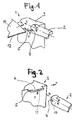
- FIG. 1 shows a simplified representation of an apparatus generally designated 1 for ultrasonic welding.
- the device has as main components a (not shown here) exciters for torsional ultrasonic vibrations excitable sonotrode 2 and an anvil 3.
- the sonotrode 2 whose longitudinal axis extends in the z-direction, is cylindrical at least in the region of the free end.
- the arrow R indicates the torsional vibrations of the sonotrode.
- Of the Anvil has an engaging member 5 which is inserted into a slot 4 in the region of a free end of the sonotrode 2.
- a lateral boundary surface of the slot forms a working surface of the sonotrode.
- the device 1 With the device 1, two plastic films 11 and 12 lying on top of each other can be welded together at the edges.
- the films 11, 12 in the x direction by a Schweissspalt which is formed by a lateral boundary of the slot 4 and the engaging member 5 inserted therein, out and welded under the action of torsional vibrations. In this way, a longitudinal seam is produced at the edge.
- the device is suitable for edge-side welding of two films and in particular of plastic films. Of course, if necessary, three or more sheets could be joined together.
- the device can also be used for continuous scoring of films (scoring, eg as a tear-open aid) or for the complete continuous separation or separation welding of films.
- plastics-coated flat structures made of paper or other laminates are also suitable.
- FIG. 2 is the Sontrode 2 in a waiting position.
- the sonotrode To create the working position (see Fig. 1 ), the sonotrode must be moved by means of (not shown here) drive means of a lifting and lowering device or even manually in the z-direction.
- the engaging member 5 is integrally formed on the anvil 3 and thus configured substantially rigid. Furthermore, it is off FIG. 2 It can be seen that the upper side 6 of the engagement member 5, which is referred to below as the attacking portion, is designed plane and lies on the xy plane.
- the engagement member 5 has a support segment 31 on the front side. This engagement member 5 serves for axial support of the sonotrode 2 in the working position ( Fig. 1 ).
- the support segment 31 is configured by way of example as a conical projection.
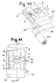
- FIGS. 3 and 4 are sectional views of the device shown. Based FIG. 3 It can be seen that the length of the engagement member 5 is greater than the diameter of the sonotrode 2 and that the engagement member 5 projects beyond the slot 4 on both sides. FIG. 3 further shows that the slot 4 is a continuous, in the x-direction extending longitudinal groove.
- the articles to be processed are impacted approximately perpendicularly (ie, in the y direction) by impacts in the ultrasonic range.
- the device according to the invention uses torsion sonotrodes, the actual loading of the objects to be connected is effected by longitudinal collisions.
- the width of the weld is predetermined by the penetration depth of the engagement member 5 in the slot 4.
- FIG. 4 shows, the groove relative to the end face 15 of the sonotrode 2 in the direction of the longitudinal axis or z-direction deepened.
- the gap 4 is designed as a rectangular cross-section groove, wherein the groove depth is denoted by t and the groove width b.
- the groove depth t is for example between 5 and 30 mm and preferably between 10 and 15 mm
- the groove width b is between 5 and 15 mm and is preferably about 10 mm.
- the gap size of the welding gap is designated by s.
- the slot has two plane-parallel to each other extending side walls 10, 13, wherein the side wall 10 of the films 11, 12 faces and forms a flat work surface 10.
- FIG. 4 shows, formed as a conical projection support segment extends in the axial direction; the apex of the cone is evidently on the z-axis.
- the engagement member 5 is not rigidly connected to the anvil, but resiliently mounted on this.
- Corresponding springs are indicated by 7 and 8. With the springs 7, 8 can be achieved that the film to be welded under the action of a biasing force when passing through the welding gap of a pressing or compressive force is subject. Further, by the floating bearing the springs 7, 8 also cause the engaging member can perform pivotal movements.
- the corresponding pivot axis is identical to the longitudinal axis z.
- the engaging member 5 in the region of the engaging portion 6, a weighing edge 20, to which a wedge surface 21 connects.
- the engaging member 5 For adjusting the width of the welding gap and / or for adjusting the contact pressure, the engaging member 5 by means of a (Adjustment mechanism, not shown here) in the y-direction movably attached to an anvil bracket.
- FIG. 6 shows a side view with the sonotrode 2 and the engaging member 5. It can be seen that the formed work surface 10 is contoured and has a plurality of rib-like, extending in the x-direction projections 16.
- the rib arrangement (or other surface profiling or contour) leads - in contrast to contourless designs - to a welded connection in which not the entire overlap area is welded.
- the rib contour fulfills the function of the energy direction sensor. This allows a targeted introduction of energy into the welding zone.
- FIG. 6 is still a support segment 31 recognizable. In contrast to the previous embodiment (see. Fig.
- the support segment 31 is not assigned to the engagement member, but the slot.
- the support segment 31 is an approximately centrally located in the groove bottom 14 conical projection. Its conical tip is evident on the z-axis and thus forms an advantageous fixed stop or zero point contact, which does not resonate in the ultrasonic welding process.
- FIGS. 7 and 8 an alternative device 1 for ultrasonic welding is shown simplified.
- the sonotrode has no slot.
- the sonotrode 2 has a step-like recess, which forms a work surface designated 10 ( FIG. 8 ).
- the working surface of the sonotrode 3 facing the top of the anvil 3 forms the engaging portion 6.
- the engaging portion 6 forms for the transport of the films 11,12 during ultrasonic welding a sliding surface for the films.
- FIGS. 7 and 8 show, run the engagement section 6 and the working surface 10 in the neutral position parallel to the longitudinal axis z of the sonotrode 2. Between the attack section 10 and work surface 10, the two superimposed films are performed to achieve the welding connection, the films are subjected to ultrasonic vibrations of the sonotrode 2.
- FIG. 9 Another alternative embodiment of a sonotrode is in FIG. 9 shown.
- the sonotrode has a flattened profile extending in the longitudinal direction z, which is formed on a cylindrical base body.
- the profile has a profile side which runs approximately parallel to the longitudinal axis z of the sonotrode 2.
- This profile page is in FIG. 9 designated 10 and forms a work surface for applying objects with ultrasonic vibrations.
- FIG. 10 shows a structural design of an apparatus for ultrasonic welding in the in FIGS. 1 to 4
- the device 1 has a converter 23 which is connected to a torsional oscillator 24.
- the torsional oscillator 24 is in turn connected to the Sontrode 2.
- the anvil 3 has an anvil holder 9, on which the engaging member 5 is attached. Thus, the vibrations can not be transferred to the anvil holder 9, this is comparatively solid.
- the device has an adjusting mechanism with which the position of the engaging member 5 in the slot 4 of the sonotrode 2 can be changed.
- 25 is an adjusting screw for displacing the engaging member in the y direction
- 26 is an adjusting screw for adjusting the angular position of the engaging member in the gap.
- the engagement member 5 is at a slight (and barely recognizable) distance from the working surface 10 of the sonotrode 2 and thus forms an advantageous welding gap (cf. Fig. 12 ).
- the engagement member 5 is supported by means of spring means (not shown here) under a bias against the sonotrode 2 in the y-direction. In the opposite direction to the direction of travel x, ie in an input-side region of the gap between the anvil and sonotrode is expanded, thus forming an insertion gap for facilitating insertion of the films in the welding gap.
- FIG. 12 the welding gap is denoted by s. Between the working surface forming side wall 10 and a received in the slot web portion 17 of the engaging member 5 is the welding gap, which may be about 0.01 mm for common thin films.
- FIG. 12 shows FIG. 12 with 30 and 30 'designated grooves and a cooling channel 28 through which a coolant is passed.
- the web section 17 lies in the in FIG. 12 shown operating position with respect to the longitudinal direction is free or does not come into contact with the bottom 14 of the groove.
- a support segment analogous to FIG. 4 or FIG. 6 is associated with either the engaging member or the bottom of the slot.
- FIG. 13 the sonotrode is shown in a plan view. Out FIG. 13 is clearly visible that the slot 4 is designed as a longitudinal groove with a groove width b.
- the slot 4 has two mutually opposite, approximately parallel side walls 10 and 13, wherein the side wall 10 forms the working surface for applying the objects with ultrasonic vibrations.
- To tune the amplitude or mass balance can be provided in the end face of the sonotrode, for example, by milling operations created recesses or depressions that can stabilize the function of the sonotrode.
- FIGS. 14 and 15 the engagement member 5 is shown.
- This component is configured approximately U-shaped and has two attachment arms 18 and 19 and a web portion 17 connecting them.
- FIG. 14 are provided by bores inputs or outputs 28, 29 and 29 'for cooling ducts can be seen, via which a coolant in the engaging member and can be derived.
- threaded holes for attaching the engaging member to the anvil holder are arranged inside next to the holes designated 29 and 29 '.
- the engaging member 5 may be a one-piece steel member created by drilling and milling operations.
- FIG. 15 shows then that the engaging member 5 on the input side has a straight portion and an adjoining it in the x-direction oblique portion (wedge portion) 21.
- the wedge portion 21 terminates in the edge 20, to which then joins the actual attack section 10 for the welding.
- the preferably central edge 20 preferably serves as a fixed stop point, which does not resonate in the ultrasonic welding process.
- the former portion and the wedge portion 21 provide the insertion gap, over which the objects to be welded on simple manner in the attack section 10 associated welding gap can be inserted. In the insertion, ie up to the edge 20 no welding takes place. From the edge 20, the oscillation amplitude increases continuously.
Landscapes
- Engineering & Computer Science (AREA)
- Mechanical Engineering (AREA)
- Life Sciences & Earth Sciences (AREA)
- Forests & Forestry (AREA)
- Textile Engineering (AREA)
- Physics & Mathematics (AREA)
- Thermal Sciences (AREA)
- Lining Or Joining Of Plastics Or The Like (AREA)
- Pressure Welding/Diffusion-Bonding (AREA)
Priority Applications (2)
| Application Number | Priority Date | Filing Date | Title |
|---|---|---|---|
| EP09162197A EP2261008A1 (fr) | 2009-06-08 | 2009-06-08 | Procédé et dispositif de traitement par ultrasons |
| US12/796,306 US20100307660A1 (en) | 2009-06-08 | 2010-06-08 | Device and Method for Ultrasonic Treatment |
Applications Claiming Priority (1)
| Application Number | Priority Date | Filing Date | Title |
|---|---|---|---|
| EP09162197A EP2261008A1 (fr) | 2009-06-08 | 2009-06-08 | Procédé et dispositif de traitement par ultrasons |
Publications (1)
| Publication Number | Publication Date |
|---|---|
| EP2261008A1 true EP2261008A1 (fr) | 2010-12-15 |
Family
ID=41258260
Family Applications (1)
| Application Number | Title | Priority Date | Filing Date |
|---|---|---|---|
| EP09162197A Withdrawn EP2261008A1 (fr) | 2009-06-08 | 2009-06-08 | Procédé et dispositif de traitement par ultrasons |
Country Status (2)
| Country | Link |
|---|---|
| US (1) | US20100307660A1 (fr) |
| EP (1) | EP2261008A1 (fr) |
Cited By (2)
| Publication number | Priority date | Publication date | Assignee | Title |
|---|---|---|---|---|
| RU2537681C2 (ru) * | 2013-05-07 | 2015-01-10 | Федеральное государственное бюджетное образовательное учреждение высшего профессионального образования "Омский государственный технический университет" | Устройство для шовной ультразвуковой сварки полимерных материалов |
| WO2017000998A1 (fr) | 2015-06-30 | 2017-01-05 | Telsonic Holding Ag | Dispositif pour souder des pièces au moyen d'ultrasons par des oscillations de torsion |
Families Citing this family (2)
| Publication number | Priority date | Publication date | Assignee | Title |
|---|---|---|---|---|
| DE102012111734A1 (de) * | 2012-12-03 | 2014-06-05 | Schunk Sonosystems Gmbh | Ultraschallschweißvorrichtung sowie Verfahren zum Verschweißen von elektrischen Leitern |
| CN111319827A (zh) * | 2020-04-02 | 2020-06-23 | 浙江欧思睦环保科技有限公司 | 一种用于生产硅藻泥粉尘包的设备 |
Citations (3)
| Publication number | Priority date | Publication date | Assignee | Title |
|---|---|---|---|---|
| JPH0629357A (ja) | 1992-06-26 | 1994-02-04 | Suzuki Motor Corp | 超音波溶着機 |
| EP1410988A1 (fr) | 2001-03-12 | 2004-04-21 | Shikoku Kakoki Co., Ltd. | Procede de scellement par ondes ultrasonores pour recipient |
| EP1930148A1 (fr) * | 2006-12-07 | 2008-06-11 | Telsonic Holding AG | Utilisation d'un dispositif destiné à la soudure par ultrasons torsionnelle |
Family Cites Families (1)
| Publication number | Priority date | Publication date | Assignee | Title |
|---|---|---|---|---|
| EP0613416A4 (en) * | 1991-10-28 | 1995-12-27 | Abbott Lab | An ultrasonically welded plastic ribbon and apparatus and process for forming same. |
-
2009
- 2009-06-08 EP EP09162197A patent/EP2261008A1/fr not_active Withdrawn
-
2010
- 2010-06-08 US US12/796,306 patent/US20100307660A1/en not_active Abandoned
Patent Citations (3)
| Publication number | Priority date | Publication date | Assignee | Title |
|---|---|---|---|---|
| JPH0629357A (ja) | 1992-06-26 | 1994-02-04 | Suzuki Motor Corp | 超音波溶着機 |
| EP1410988A1 (fr) | 2001-03-12 | 2004-04-21 | Shikoku Kakoki Co., Ltd. | Procede de scellement par ondes ultrasonores pour recipient |
| EP1930148A1 (fr) * | 2006-12-07 | 2008-06-11 | Telsonic Holding AG | Utilisation d'un dispositif destiné à la soudure par ultrasons torsionnelle |
Cited By (4)
| Publication number | Priority date | Publication date | Assignee | Title |
|---|---|---|---|---|
| RU2537681C2 (ru) * | 2013-05-07 | 2015-01-10 | Федеральное государственное бюджетное образовательное учреждение высшего профессионального образования "Омский государственный технический университет" | Устройство для шовной ультразвуковой сварки полимерных материалов |
| WO2017000998A1 (fr) | 2015-06-30 | 2017-01-05 | Telsonic Holding Ag | Dispositif pour souder des pièces au moyen d'ultrasons par des oscillations de torsion |
| US10532424B2 (en) | 2015-06-30 | 2020-01-14 | Telsonic Holding Ag | Device for welding components by means of ultrasound |
| US11247294B2 (en) | 2015-06-30 | 2022-02-15 | Telsonic Holding Ag | Device for welding components by means of ultrasound |
Also Published As
| Publication number | Publication date |
|---|---|
| US20100307660A1 (en) | 2010-12-09 |
Similar Documents
| Publication | Publication Date | Title |
|---|---|---|
| DE3688074T2 (de) | Ultraschallschweissvorrichtung mit kontaktflaechen. | |
| DE69123222T2 (de) | Ultrasonisches Schneidverfahren | |
| EP2219848B1 (fr) | Sonotrode avec fente en u | |
| EP1849569B2 (fr) | Dispositif destiné à usiner des pièces à l'aide d'ultrasons et procédé de fonctionnement d'un tel dispositif | |
| EP1140474B1 (fr) | Procede pour maintenir constante la largeur moyenne de l'espace entre une sonotrode d'un systeme a ultrasons et un outil, se presentant sous la forme d'une surface correspondante, d'une unite de coupe a ultrasons | |
| EP2945793B1 (fr) | Dispositif de soudage par ultrasons pourvu d'un contre-outil à découplage vibratoire | |
| DE102009027021B3 (de) | Ultraschall-Schweißvorrichtung und Verfahren zum Verschweißen zweier Bauteile | |
| EP2812174B1 (fr) | Procédé et dispositif pour confectionner des sacs tubulaires à partir de minces feuilles plastiques au moyen d'un procédé de soudage par ultrasons | |
| EP2261008A1 (fr) | Procédé et dispositif de traitement par ultrasons | |
| EP3120950B1 (fr) | Élément de transmission pour un dispositif de rivetage, dispositif de rivetage, dispositif de fabrication et procé de détermination d'un comportement aux vibrations | |
| EP3117923B1 (fr) | Procédé de liaison d'au moins deux composants au moyen d'un dispositif de rivetage et dispositif de fabrication | |
| EP4363150A1 (fr) | Système de soudage par ultrasons et procédé d'usinage par soudage de matériaux | |
| DE102021131399A1 (de) | Verfahren und vorrichtung zum aufbringen einer aktiven verbindungskraft beim laserschweissen von sich überlappenden werkstücken | |
| EP3552729B1 (fr) | Dispositif d'installation de rivets auto-poinçonneurs | |
| EP3124133B1 (fr) | Dispositif de rivetage avec un outil contre-support et utilisation d'un tel outil | |
| EP3034276A1 (fr) | Composant ayant une connexion par liaison de matière et procédé de jointure | |
| EP3592498B1 (fr) | Dispositif de soudage par ultrasons et procédé de soudage par ultrasons | |
| EP2663416B1 (fr) | Procédé et dispositif pour conférer un mouvement oscillant à une masse | |
| DE102015218181A1 (de) | Ultraschallbearbeitungseinrichtung und -verfahren und hierfür ausgeführte Sonotrode | |
| DE102019107539A1 (de) | Gestell für eine Bearbeitungsmaschine und Verfahren zum Bearbeiten eines Werkstücks mit derselben | |
| DE19809581A1 (de) | Vorrichtung zum Bearbeiten von metallischem Material | |
| EP3552731B1 (fr) | Unité de pose pour un dispositif rivet auto-poinçonneur et dispositif rivet auto-poinçonneur | |
| EP1996365B1 (fr) | Procede et dispositif de soudage d'elements en materiaux metalliques | |
| EP4255720B1 (fr) | Élément d'usinage avec élément de structure | |
| EP4259419B1 (fr) | Compensation de la déformation thermique des sonotrodes |
Legal Events
| Date | Code | Title | Description |
|---|---|---|---|
| PUAI | Public reference made under article 153(3) epc to a published international application that has entered the european phase |
Free format text: ORIGINAL CODE: 0009012 |
|
| AK | Designated contracting states |
Kind code of ref document: A1 Designated state(s): AT BE BG CH CY CZ DE DK EE ES FI FR GB GR HR HU IE IS IT LI LT LU LV MC MK MT NL NO PL PT RO SE SI SK TR |
|
| AX | Request for extension of the european patent |
Extension state: AL BA RS |
|
| 17P | Request for examination filed |
Effective date: 20110416 |
|
| 17Q | First examination report despatched |
Effective date: 20110511 |
|
| GRAP | Despatch of communication of intention to grant a patent |
Free format text: ORIGINAL CODE: EPIDOSNIGR1 |
|
| INTG | Intention to grant announced |
Effective date: 20130719 |
|
| STAA | Information on the status of an ep patent application or granted ep patent |
Free format text: STATUS: THE APPLICATION IS DEEMED TO BE WITHDRAWN |
|
| 18D | Application deemed to be withdrawn |
Effective date: 20131130 |