EP2261018B1 - Verfahren zur Regelung eines Servoantriebssystems und Servoantriebssystem einer Presse - Google Patents
Verfahren zur Regelung eines Servoantriebssystems und Servoantriebssystem einer Presse Download PDFInfo
- Publication number
- EP2261018B1 EP2261018B1 EP10009358.2A EP10009358A EP2261018B1 EP 2261018 B1 EP2261018 B1 EP 2261018B1 EP 10009358 A EP10009358 A EP 10009358A EP 2261018 B1 EP2261018 B1 EP 2261018B1
- Authority
- EP
- European Patent Office
- Prior art keywords
- ram
- servo
- speed
- servo motor
- torque
- Prior art date
- Legal status (The legal status is an assumption and is not a legal conclusion. Google has not performed a legal analysis and makes no representation as to the accuracy of the status listed.)
- Expired - Lifetime
Links
- 238000000034 method Methods 0.000 title claims description 12
- 230000001105 regulatory effect Effects 0.000 title claims description 12
- 239000003990 capacitor Substances 0.000 claims abstract description 15
- 230000001629 suppression Effects 0.000 claims abstract description 6
- 238000004080 punching Methods 0.000 claims description 100
- 230000009467 reduction Effects 0.000 claims description 16
- 230000033001 locomotion Effects 0.000 claims description 14
- 239000000463 material Substances 0.000 claims description 8
- 230000009471 action Effects 0.000 claims description 7
- 230000003247 decreasing effect Effects 0.000 claims description 6
- 238000004804 winding Methods 0.000 claims description 6
- 239000002131 composite material Substances 0.000 claims description 2
- 238000010586 diagram Methods 0.000 description 14
- 230000007246 mechanism Effects 0.000 description 11
- 238000000605 extraction Methods 0.000 description 9
- 230000005611 electricity Effects 0.000 description 6
- 230000001172 regenerating effect Effects 0.000 description 6
- 230000001133 acceleration Effects 0.000 description 5
- 238000007796 conventional method Methods 0.000 description 4
- 230000002411 adverse Effects 0.000 description 3
- 230000005540 biological transmission Effects 0.000 description 3
- 230000001276 controlling effect Effects 0.000 description 2
- 230000004044 response Effects 0.000 description 2
- 230000002441 reversible effect Effects 0.000 description 2
- 238000005406 washing Methods 0.000 description 2
- 230000008859 change Effects 0.000 description 1
- 230000000295 complement effect Effects 0.000 description 1
- 238000001816 cooling Methods 0.000 description 1
- 230000001934 delay Effects 0.000 description 1
- 230000003111 delayed effect Effects 0.000 description 1
- 230000001419 dependent effect Effects 0.000 description 1
- 239000000314 lubricant Substances 0.000 description 1
Images






Classifications
-
- B—PERFORMING OPERATIONS; TRANSPORTING
- B30—PRESSES
- B30B—PRESSES IN GENERAL
- B30B15/00—Details of, or accessories for, presses; Auxiliary measures in connection with pressing
- B30B15/14—Control arrangements for mechanically-driven presses
- B30B15/148—Electrical control arrangements
-
- B—PERFORMING OPERATIONS; TRANSPORTING
- B30—PRESSES
- B30B—PRESSES IN GENERAL
- B30B1/00—Presses, using a press ram, characterised by the features of the drive therefor, pressure being transmitted directly, or through simple thrust or tension members only, to the press ram or platen
-
- B—PERFORMING OPERATIONS; TRANSPORTING
- B30—PRESSES
- B30B—PRESSES IN GENERAL
- B30B1/00—Presses, using a press ram, characterised by the features of the drive therefor, pressure being transmitted directly, or through simple thrust or tension members only, to the press ram or platen
- B30B1/26—Presses, using a press ram, characterised by the features of the drive therefor, pressure being transmitted directly, or through simple thrust or tension members only, to the press ram or platen by cams, eccentrics, or cranks
- B30B1/266—Drive systems for the cam, eccentric or crank axis
-
- B—PERFORMING OPERATIONS; TRANSPORTING
- B30—PRESSES
- B30B—PRESSES IN GENERAL
- B30B15/00—Details of, or accessories for, presses; Auxiliary measures in connection with pressing
- B30B15/14—Control arrangements for mechanically-driven presses
-
- Y—GENERAL TAGGING OF NEW TECHNOLOGICAL DEVELOPMENTS; GENERAL TAGGING OF CROSS-SECTIONAL TECHNOLOGIES SPANNING OVER SEVERAL SECTIONS OF THE IPC; TECHNICAL SUBJECTS COVERED BY FORMER USPC CROSS-REFERENCE ART COLLECTIONS [XRACs] AND DIGESTS
- Y10—TECHNICAL SUBJECTS COVERED BY FORMER USPC
- Y10T—TECHNICAL SUBJECTS COVERED BY FORMER US CLASSIFICATION
- Y10T74/00—Machine element or mechanism
- Y10T74/18—Mechanical movements
- Y10T74/18056—Rotary to or from reciprocating or oscillating
-
- Y—GENERAL TAGGING OF NEW TECHNOLOGICAL DEVELOPMENTS; GENERAL TAGGING OF CROSS-SECTIONAL TECHNOLOGIES SPANNING OVER SEVERAL SECTIONS OF THE IPC; TECHNICAL SUBJECTS COVERED BY FORMER USPC CROSS-REFERENCE ART COLLECTIONS [XRACs] AND DIGESTS
- Y10—TECHNICAL SUBJECTS COVERED BY FORMER USPC
- Y10T—TECHNICAL SUBJECTS COVERED BY FORMER US CLASSIFICATION
- Y10T74/00—Machine element or mechanism
- Y10T74/18—Mechanical movements
- Y10T74/18056—Rotary to or from reciprocating or oscillating
- Y10T74/18248—Crank and slide
-
- Y—GENERAL TAGGING OF NEW TECHNOLOGICAL DEVELOPMENTS; GENERAL TAGGING OF CROSS-SECTIONAL TECHNOLOGIES SPANNING OVER SEVERAL SECTIONS OF THE IPC; TECHNICAL SUBJECTS COVERED BY FORMER USPC CROSS-REFERENCE ART COLLECTIONS [XRACs] AND DIGESTS
- Y10—TECHNICAL SUBJECTS COVERED BY FORMER USPC
- Y10T—TECHNICAL SUBJECTS COVERED BY FORMER US CLASSIFICATION
- Y10T74/00—Machine element or mechanism
- Y10T74/19—Gearing
- Y10T74/19023—Plural power paths to and/or from gearing
- Y10T74/19051—Single driven plural drives
- Y10T74/19056—Parallel
-
- Y—GENERAL TAGGING OF NEW TECHNOLOGICAL DEVELOPMENTS; GENERAL TAGGING OF CROSS-SECTIONAL TECHNOLOGIES SPANNING OVER SEVERAL SECTIONS OF THE IPC; TECHNICAL SUBJECTS COVERED BY FORMER USPC CROSS-REFERENCE ART COLLECTIONS [XRACs] AND DIGESTS
- Y10—TECHNICAL SUBJECTS COVERED BY FORMER USPC
- Y10T—TECHNICAL SUBJECTS COVERED BY FORMER US CLASSIFICATION
- Y10T74/00—Machine element or mechanism
- Y10T74/19—Gearing
- Y10T74/19642—Directly cooperating gears
- Y10T74/19698—Spiral
-
- Y—GENERAL TAGGING OF NEW TECHNOLOGICAL DEVELOPMENTS; GENERAL TAGGING OF CROSS-SECTIONAL TECHNOLOGIES SPANNING OVER SEVERAL SECTIONS OF THE IPC; TECHNICAL SUBJECTS COVERED BY FORMER USPC CROSS-REFERENCE ART COLLECTIONS [XRACs] AND DIGESTS
- Y10—TECHNICAL SUBJECTS COVERED BY FORMER USPC
- Y10T—TECHNICAL SUBJECTS COVERED BY FORMER US CLASSIFICATION
- Y10T74/00—Machine element or mechanism
- Y10T74/20—Control lever and linkage systems
- Y10T74/20207—Multiple controlling elements for single controlled element
- Y10T74/20341—Power elements as controlling elements
-
- Y—GENERAL TAGGING OF NEW TECHNOLOGICAL DEVELOPMENTS; GENERAL TAGGING OF CROSS-SECTIONAL TECHNOLOGIES SPANNING OVER SEVERAL SECTIONS OF THE IPC; TECHNICAL SUBJECTS COVERED BY FORMER USPC CROSS-REFERENCE ART COLLECTIONS [XRACs] AND DIGESTS
- Y10—TECHNICAL SUBJECTS COVERED BY FORMER USPC
- Y10T—TECHNICAL SUBJECTS COVERED BY FORMER US CLASSIFICATION
- Y10T74/00—Machine element or mechanism
- Y10T74/20—Control lever and linkage systems
- Y10T74/20207—Multiple controlling elements for single controlled element
- Y10T74/20341—Power elements as controlling elements
- Y10T74/2036—Pair of power elements
-
- Y—GENERAL TAGGING OF NEW TECHNOLOGICAL DEVELOPMENTS; GENERAL TAGGING OF CROSS-SECTIONAL TECHNOLOGIES SPANNING OVER SEVERAL SECTIONS OF THE IPC; TECHNICAL SUBJECTS COVERED BY FORMER USPC CROSS-REFERENCE ART COLLECTIONS [XRACs] AND DIGESTS
- Y10—TECHNICAL SUBJECTS COVERED BY FORMER USPC
- Y10T—TECHNICAL SUBJECTS COVERED BY FORMER US CLASSIFICATION
- Y10T83/00—Cutting
- Y10T83/869—Means to drive or to guide tool
- Y10T83/8726—Single tool with plural selective driving means
-
- Y—GENERAL TAGGING OF NEW TECHNOLOGICAL DEVELOPMENTS; GENERAL TAGGING OF CROSS-SECTIONAL TECHNOLOGIES SPANNING OVER SEVERAL SECTIONS OF THE IPC; TECHNICAL SUBJECTS COVERED BY FORMER USPC CROSS-REFERENCE ART COLLECTIONS [XRACs] AND DIGESTS
- Y10—TECHNICAL SUBJECTS COVERED BY FORMER USPC
- Y10T—TECHNICAL SUBJECTS COVERED BY FORMER US CLASSIFICATION
- Y10T83/00—Cutting
- Y10T83/869—Means to drive or to guide tool
- Y10T83/8821—With simple rectilinear reciprocating motion only
- Y10T83/8841—Tool driver movable relative to tool support
- Y10T83/8843—Cam or eccentric revolving about fixed axis
-
- Y—GENERAL TAGGING OF NEW TECHNOLOGICAL DEVELOPMENTS; GENERAL TAGGING OF CROSS-SECTIONAL TECHNOLOGIES SPANNING OVER SEVERAL SECTIONS OF THE IPC; TECHNICAL SUBJECTS COVERED BY FORMER USPC CROSS-REFERENCE ART COLLECTIONS [XRACs] AND DIGESTS
- Y10—TECHNICAL SUBJECTS COVERED BY FORMER USPC
- Y10T—TECHNICAL SUBJECTS COVERED BY FORMER US CLASSIFICATION
- Y10T83/00—Cutting
- Y10T83/869—Means to drive or to guide tool
- Y10T83/8821—With simple rectilinear reciprocating motion only
- Y10T83/8841—Tool driver movable relative to tool support
- Y10T83/8844—Gear actuated tool support
Definitions
- the present invention relates to a method of regulating a servo drive system of a turret punch press machine and to a servo drive system of a press machine, which is applied to a turret punch press, and more particularly, to a continuous working system of a press machine applied to a turret punch press.
- US 5 832 816 A discloses a ram driving device for a press machine wherein a plurality of servomotors are driven in synchronism with each other, to rotate a horizontal drive axle from which rotational motion is converted into up/down motion.
- the movement stroke and the vertical speed of the ram can be controlled freely by changing the rotational speed of the plurality of servomotors in synchronism with each other, and the press power can be increased by use of an appropriate number of servomotors driven in synchronism with each other.
- JP 2000 358382 A shows a driving device for a three-phase motor with which a constant, freely adjustable motor terminal voltage can be generated irrespective of the power supply voltage.
- the driving device comprises a PWM inverter operative in either the power running mode for driving the AC motor or the power regenerative mode, wherein energy is returned from the motor to the inverter and temporarily stored in the capacitor of the DC power circuit.
- JP 2001 276467 A provides an inverter washing machine comprising a brushless motor for altematingly rotating the washing rotor in a clockwise and counter-clockwise direction, Hall sensors for detecting the position of the rotor of the motor, and an auxiliary control part having an inverter and driving the motor according to the position signals outputted from the Hall sensors.
- the auxiliary control part further comprises capacitors for storing the regenerative energy produced when the motor is temporarily stopped by the electromagnetic brake.
- the punch press drive device disclosed in EP 0 827 790 A2 drives a punch by a servomotor and is arranged with a output characteristic adjustment means for adjusting the torque with respect to the speed of the servomotor and a control means for controlling that output characteristic adjustment means.
- the control means lowers the characteristics of the torque when the speed of the punch exceeds a predetermined speed, so that the range of speeds in which the servomotor may be used increases and there is no insufficient output at low speed times.
- JP 2000 288792 A is another servopress having one or a plurality of direct drives, each in the form of a servomotor on a crank mechanism, the crankshaft of which acts on a slide via a crank arm and a connecting rod. According to this configuration, when the servomotor is driven the rotational motion of the crankshaft is transformed into a linear motion through the crank arm and connecting rod and the slide is vertically moved.
- the conventional electric punch press generates a torque necessary for working by using a mechanism such as a toggle and a flywheel. Therefore, the inertia caused by this mechanism delays the reciprocating motion of the ram.
- an operation shaft which vertically moves the ram and a main shaft of a servo motor is driven through a power transmission mechanism such as a gear, and a loss or a delay is generated by the power transmission mechanism. Even if the speed of the servo motor is controlled, the driving speed of the ram can not follow the speed of the servo motor easily, and therefore the conventional technique is not suitable for controlling the speed of the ram.
- the conventional technique has problems that since the punching speed is set substantially at a constant value irrespective of the weight of the load, if the punching speed is set lower to decrease the noise, the operation efficiency is largely deteriorated, and if the punching speed is set higher to enhance the operation efficiency, a large noise is generated and thus, reduction of noise and enhancement of operation efficiency can not be satisfied at the same time.
- a predetermined punching pattern is switched in a hydraulic press system depending upon the plate thickness, material, and the like to satisfy both the noise reduction and increase of punching speed. Therefore, complicated control systems such as high-speed processing hardware and software are required.
- a hydraulic punch press using hydraulic pressure as the driving source of the ram and an electric punch press using a servo motor.
- the same punching die such as a nibble is used and a work is continuously punched in some cases.
- a speedup of the ram is required.
- the conventional technique has problems that since the punching speed is set substantially at a constant value irrespective of the weight of the load, if the punching speed is set lower to decrease the noise, the operation efficiency is largely deteriorated, and if the punching speed is set higher to enhance the operation efficiency, a large noise is generated and thus, reduction of noise and enhancement of operation efficiency can not be satisfied at the same time.
- the object of the invention is achieved by a method of regulating a servo drive system of a turret punch press machine which is characterized by what is stated in the independent claim 1, and a servo drive system of a turret punch press machine which is characterized by what is stated in the independent claim 9.
- Preferred embodiments of the invention are disclosed in the dependent claims.
- the servo drive system of the turret punch press machine uses a servo motor as a driving source of a ram, wherein the servo motor uses a torque based on speed-torque characteristics of the servo motor to generate ram pressure, wherein an operation shaft which vertically moves the ram is directly driven using the servo motor, wherein the servo motor has the speed-torque characteristics in which a motor torque of the servo motor, at which a capacity of electric energy supplied by a servo amplifier is determined, defines the motor torque at which, an optimal punching pattern of the ram is generated from a light load to a heavy load according to a type of workpiece to be worked by the turret punch press machine, and wherein the servo motor has the further speed-torque characteristics in which:
- Fig. 1 is a vertical sectional view of an essential portion showing an embodiment of a servo drive system (continuous working system) of a turret punch press machine according to the present invention
- Fig. 2 is a right side view thereof.
- the servo drive system (continuous working system) 1 of the press machine is applied to a turret punch press 10.
- the turret punch press 10 has an eccentric shaft 20 which is pivotally supported by bearings 12a and 12b provided on frames 11a and 11b which stand in parallel to each other.
- the eccentric shaft 20 has an eccentric shaft portion 20e located substantially at a central portion between the frames 11a and 11b.
- a ram 22 is mounted on the eccentric shaft portion 20e through a connecting rod 21. If the eccentric shaft 20 rotates or turns, the ram 22 is vertically moved through the connecting rod 21 along a ram guide 23, and a striker 24 mounted on a lower end of the ram 22 is also vertically moved in unison with the ram 22. When the ram 22 moves downward, the striker 24 pushes a punching die 26 mounted on a turret 25 to punch a work out.
- the eccentric shaft 20 is provided at its opposite ends with extensions 20a and 20b which extend outward from the frames 11a and 11b.
- Servo motors 30a and 30b using the extensions 20a and 20b as motor main shafts 31a and 31b are respectively mounted on outer sides of the frames 11a and 11b.
- the extension 20a of the eccentric shaft 20 is constituted as the motor main shaft 31a. That is, a sleeve 33a is provided at its outer periphery with an even number (four) of magnetic pole magnets (permanent magnets) 32a in a circumferential direction at predetermined distances (90°) from one another. The sleeve 33a is fitted around and fixed to a periphery of the extension 20a of the eccentric shaft 20 through a bush 34a, thereby constituting a rotor 35a.
- the extension 20a of the eccentric shaft 20 serves as a center axis of the rotor 35a.
- the extension 20a is the motor main shaft 31a itself. Therefore, the servo motor 30a uses the extension 20a, i.e., the eccentric shaft 20 substantially as the rotor 35a.
- an outer cylinder 36a around which three-phase armature windings Ua, Va, and Wa are wound is fitted over the rotor 35a and fixed to the frame 11a, thereby constituting a stator 37a.
- the extension 20b of the eccentric shaft 20 is constituted as the motor main shaft 31b. That is, a sleeve 33b is provided at its outer periphery with an even number (four) of magnetic pole magnets (permanent magnets) 32b in a circumferential direction at predetermined distances (90°) from one another. The sleeve 33b is fitted around and fixed to a periphery of the extension 20b of the eccentric shaft 20 through a bush 34b, thereby constituting a rotor 35b.
- the extension 20b of the eccentric shaft 20 serves as a center axis of the rotor 35b.
- the extension 20b is the motor main shaft 31b itself. Therefore, the servo motor 30b uses the extension 20b, i.e., the eccentric shaft 20 substantially as the rotor 35b.
- an outer cylinder 36b around which three-phase armature windings Ub, Vb, and Wb are wound is fitted over the rotor 35b and fixed to the frame 11b, thereby constituting a stator 37b.
- the servo motor 30a and the servo motor 30b are the same, but they are symmetric with each other in a mirror image manner. Except this point, the servo motors 30a and 30b are completely the same, and they are integrally provided with the rotors 35a and 35b. Therefore, a rotary encoder 38 which detects rotation angles of the rotors 35a and 35b is provided on one of the servo motors (e.g., 30b) and the rotary encoder 38 is commonly used.
- the servo motors 30a and 30b have the same speed-torque characteristics, and a torque based on the speed-torque characteristics is synthesized and used. With this, the servo motors 30a and 30b have a function of generating necessary ram pressure.
- the magnetic pole of the rotor 35a of the servo motor 30a position of the magnetic pole in the circumferential direction of the magnetic pole magnet 32a
- the magnetic pole of the rotor 35b of the servo motor 30b position of the magnetic pole in the circumferential direction of the magnetic pole magnet 32b
- the three-phase armature windings Ua, Va, and Wa of the servo motor 30a and the three-phase armature windings Ub, Vb, and Wb of the servo motor 30b are positioned and mounted symmetrically with each other in the mirror image manner in the circumferential direction.
- a power driver 42a of a servo amplifier 40a which is a control circuit of the servo motor 30a, and a power driver 42b of a servo amplifier 40b which is a control circuit of the servo motor 30b are driven by the same gate signal, only three-phase alternating current having the same phase and same current values flows to the servo motor 30a and the servo motor 30b.
- a torque vector of the servo motor 30a and a torque vector of the servo motor 30b have the same phase and thus, a composite torque of the servo motor 30a and the servo motor 30b becomes an exact sum of torques of the servo motors 30a and 30b.
- This relation is the same irrespective of whether the servo motors 30a and 30b are separately formed as shown in Figs. 1 and 3 or the servo motors 30a and 30b are integrally formed as the three-phase parallel circuit as shown in Figs. 14 and 16 .
- the servo amplifier 40a includes a converter 41a which A-D converts three-phase commercial alternating power supply, a power driver 42a, a reactor 43a which is provided on a front stage of the power driver 42a and which suppresses peak current by cutting off high frequency current component, and a capacitor 44a for storage having a large capacity.
- Six power transistors Q of the power driver 42a are driven by a gate signal so that the servo amplifier 40a drives the servo motor 30a by three-phase alternating output of the power driver 42a.
- Diodes D for flowing regenerative current generated during speed reducing period of the servo motor 30a are connected to the power transistors Q of the power driver 42a.
- the regenerative current flows into the capacitor 44a and is accumulated as regenerative electricity.
- the capacitor 44a supplies electric energy which runs short due to suppression of the peak current by the reactor 43a using the regenerative electricity, i.e., the capacitor 44a supplies high speed operation electric energy and/or punching out electric energy.
- the servo amplifier 40b has the same structure as that of the servo amplifier 40a.
- the servo motors 30a and 30b reciprocate and turn the eccentric shaft 20 through an angle range ⁇ corresponding to a space between positions L and H so that the eccentric shaft portion 20e of the eccentric shaft 20 vertically moves between the L position corresponding to a case where the ram 22 is in a predetermined lower end position required for punching working (see Figs. 4A to 4C ) and the H position corresponding to a case where the ram 22 is returned from the L position and is in an upper end position where the striker 24 at a lower end of the ram 22 is separated from an upper surface of the punching die 26. With this, a work is punched.
- the L position of the eccentric shaft portion 20e of the eccentric shaft 20 corresponding to the lower end position of the ram 22 is set to a position slightly short of and above a bottom dead center B of the entire vertically possible stroke of the ram 22 determined by an eccentric amount E (distance between an axis of the eccentric shaft 20 and an axis of the eccentric shaft portion 20e) of the eccentric shaft 20.
- the H position of the eccentric shaft portion 20e of the eccentric shaft 20 corresponding to the upper end position of the ram 22 is set to a position slightly below a medium height M of the entire vertically possible stroke of the ram 22. That is, although the reciprocating turning angle range ⁇ of the eccentric shaft 20 depends on the stroke of the punching die 26 to be used, the angle range ⁇ is set to about 40° to 60°.
- the eccentric shaft portion 20e (i.e., ram 22) of the eccentric shaft 20 is positioned on a top dead center T when the die is to be exchanged or the turret is to be rotated.
- the servo motors 30a and 30b turn the eccentric shaft portion 20e of the eccentric shaft 20 to the L position corresponding to the lower end position of the ram 22 from the top dead center T, thereby lowering the ram 22, and after a first punching working is carried out, the eccentric shaft portion 20e is returned to the H position corresponding to the upper end position of the ram 22 where the ram 22 stands-by.
- the eccentric shaft portion 20e of the eccentric shaft 20 is turned such as to reciprocate through the reciprocating turning angle range ⁇ between the H position and the L position.
- the servo motors 30a and 30b are arranged such that the opposite half circumferential range is also used as required as shown in Fig. 4C . It is preferable that the side shown in Fig. 4B and the side shown in Fig. 4C are switched whenever the die is to be exchanged or the turret is to be rotated, or automatically according to a predetermined number of punching operations.
- the pair of servo motors 30a and 30b are respectively mounted on the outer sides of the frames 11a and 11b. Therefore, no distortion is generated in mechanical parts corresponding to one side of the eccentric shaft 20. That is, for example, the servo motors 30a and 30b are integrally formed as one servo motor (30) including a three-phase parallel circuit.
- the servo motor (30) can be mounted only on the outer side of the frame 11a or the frame 11b. In this case, since a stress caused by the weight of the servo motor (30) is received only by one frame 11a or 11b, distortion is generated in both the frames 11a and 11b, and distortion is generated due to uneven heat generated by the servo motor (30).
- the servo motors 30a and 30b directly drive the eccentric shaft 20, and the eccentric shaft 20 continuously reciprocates and turns only in the reciprocating turning angle range ⁇ between the L position corresponding to the lower end position of the ram 22 and the H position corresponding to the upper end position of the ram 22.
- This operation is extremely effective for speeding up the ram 22 when a work is subjected to continuous punching working.
- Fig. 5 shows examples 1) and 2) of speed-torque characteristics of the servo motors 30a and 30b.
- Fig. 5 shows the upper limit speed at which the servo motors 30a and 30b can be operated when a driving torque of the ram 22 required for a load applied to the ram 22 is to be generated.
- the noise is large when the punching speed by driving of a ram is fast, the noise becomes smaller when the punching speed becomes slower, and when the punching speed is constant, the noise is small when the load is light, and as the load becomes heavier, the noise becomes larger. From this fact, like the speed-torque characteristics of the servo motors 30a and 30b shown in Fig. 5 , as the load is heavier, the ram speed becomes slower, and this reduces the noise. Further, it is apparent, from the following actually measured data of punching working of various works and feature extraction waveform data based thereon, that such reduction in ram speed does not deteriorate the operation efficiency.
- Fig. 6 shows the actually measured data of a punching working when there is no work
- Fig. 7A shows the feature extraction waveform data based on the actually measured data
- Fig. 7B shows the punching torque-speed characteristics based on the actually measured data.
- a speed curve and a torque curve rise in a normal rotation direction to keep constant values.
- a ram position curve is substantially uniformly lowered from the upper end position (corresponding to H position) to the lower end position (corresponding to L position).
- the speed curve and the torque curve rise in the reverse rotation direction to keep the constant values.
- the ram position curve is substantially uniformly moved upward from the lower end position (corresponding to L position) to the upper end position (corresponding to H position).
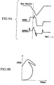
- Fig. 8 shows the actually measured data of a punching working when a thin plate work is punched out using a punch having a small diameter.
- Fig. 9A shows the feature extraction waveform data based on the actually measured data, and
- Fig. 9B shows the punching torque-speed characteristics based on the actually measured data.
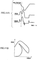
- Fig. 10 shows the actually measured data of a punching working when a thin plate work is punched out using a punch having a large diameter.
- Fig. 11A shows the feature extraction waveform data based on the actually measured data, and
- Fig. 11B shows the punching torque-speed characteristics based on the actually measured data.
- the lowering speed of the ram position curve is also accelerated larger than that shown in Figs. 8 to 9B .
- the ram position curve substantially uniformly rises from the lower end position (corresponding to L position) to the upper end position (corresponding to H position).
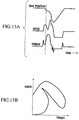
- Fig. 12 shows the actually measured data of a punching working when a thick plate work is punched out using a punch having a small diameter.
- Fig. 13A shows the feature extraction waveform data based on the actually measured data, and
- Fig. 13B shows the punching torque-speed characteristics based on the actually measured data.
- the motor converts the supplied electric energy into energy applied to a load.
- the magnitude of the supplied electric energy is determined by the servo amplifiers 40a and 40b, voltage of power supply is also limited, and voltage equal to or greater than the power supply voltage can not be applied.
- the motor torque can be divided into a torque for generating kinetic energy of the ram 22 and a torque for generating the punching pressurizing force.
- the deceleration of the lowering speed of the ram 22 is the characteristic which is extremely effective for reducing a noise caused by the punching operation of punching, a noise caused by vibration, and vibration itself. That is, when the required pressurizing force (the number of pressure tons) is relatively small depending upon the conditions such as the plate thickness and material of the work, since the speed reduction of the lowering speed of the ram 22 is small, the punching action with light load becomes relatively fast. When the required pressurizing force (the number of pressure tons) is relatively large, since the speed reduction of the lowering speed of the ram 22 is large, the punching action with heavy load becomes relatively slow. The variation in punching speed is automatically determined according to the required pressurizing force (the number of pressure tons).
- the speed-torque characteristics of the servo motors 30a and 30b to be used are set such that motor torques of the servo motors 30a and 30b at which the capacity of the electric energy supplied by the servo amplifiers 40a and 40b is determined become motor torques at which an optimal punching pattern (lowering pattern of the ram 22) is generated from a light load to a heavy load according to the type of work to be worked on by the turret punch press 10. With this, a noise caused by the punching action of punching, a noise caused by vibration, and the vibration itself can be reduced.
- the punch press that can reduce a noise caused by the punching action of punching, a noise caused by vibration, and the vibration itself based on the explanation with reference to Figs. 5 to 13B has the same speed-torque characteristics as those of the servo motors 30a and 30b of the servo drive system (continuous working system) 1 according to the present invention.
- a value of each of the reactors 43a and 43b is defined as L
- a resistance is high to a high frequency component.
- the peak current of the reactors 43a and 43b can be suppressed by cutting off the high frequency current component.
- the peak electricity of the servo amplifiers 40a and 40b can be suppressed, if reactors 43a and 43b having extremely large L values are used, the peak electricity can be adjusted to such a value that it is substantially unnecessary to change contracted electric power with respect to a power company, as compared with a case where a mechanism such as a toggle and a flywheel is utilized.
- the capacitors 44a and 44b To complement the supply of the high speed operation electric energy and/or the supply of the punching operation electric energy from the servo amplifiers 40a and 40b to the servo motors 30a and 30b, there are provided the capacitors 44a and 44b. If the capacitors 44a and 44b having significantly large capacity are used, electric energy required for the high speed operation and/or electric energy required for the punching operation can sufficiently be supplied from the servo amplifiers 40a and 40b to the servo motors 30a and 30b.
- the reactors 43a and 43b having the significantly large L values and the capacitors 44a and 44b having the significantly large capacity are used, the peak electricity can be reduced as desired, and the high speed punching working can be carried out according to proper performance of the turret punch press 10.
- both the servo motors 30a and 30b are integrally operated in the present embodiment, the present invention is not limited to this.
- the load is extremely light and a work can sufficiently be subjected to the working using torque of one of the servo motors 30a and 30b, only one of them may be energized and operated.
- both the servo motors 30a and 30b are integrally operated with respect to such an extremely light load, there is a possibility that the lowering speed of the ram 22 becomes moderate and the noise is reduced, and power may be saved.
- Fig. 14 is a vertical sectional view of an essential portion showing another embodiment of the servo drive system (continuous working system) of the press machine according to the present invention
- Fig. 15 is a right side view of the essential portion.
- a servo drive system (continuous working system) 101 of this press machine is applied to a turret punch press 110.
- the turret punch press 110 uses one servo motor 130 which integrally includes servo motors 30a and 30b as a three-phase parallel circuit instead of the pair of servo motors 30a and 30b.
- the turret punch press 110 has the same speed-torque characteristics as those of the servo motors 30a and 30b.
- the servo motor 130 is larger than one of the servo motors 30a and 30b in size and correspondingly, an eccentric shaft 120 is formed only at its one end with an extension 120a extending longer than the extension 20a.
- a servo motor 130 using this extension 120a as a motor main shaft 131 is mounted on an outer side of a frame 111a.
- servo drive system (continuous working system) 101 of the press machine are the same as those of the servo drive system (continuous working system) 1 of the press machine shown in Figs. 1 and 2 . Therefore, the elements of the servo drive system (continuous working system) 101 which are the same as those of the system shown in Figs. 1 and 2 are designated with the reference numbers to which 100 is added, and detailed explanation of the structures of various portions of the servo drive system (continuous working system) 101 of the press machine will be omitted.
- the operation of the servo drive system (continuous working system) 101 of the press machine is also the same as that of the servo drive system (continuous working system) 1 of the press machine.
- a single drive turret punch press 110 having only one servo motor 130 and a twin drive turret punch press 10 having a pair of servo motors 30a and 30b are compared with each other, there are following differences. That is, in the single drive turret punch press 110, since a stress caused by the weight of the servo motor 130 is received only by the frame 111b, distortion is generated in the frames 111a and 111b. Further, a distortion caused by non-uniform heat is also generated by the heat of the servo motor 130. Stresses of the bearings 112a and 112b are also different from each other. Therefore, it is necessary to take measures against the problems. On the other hand, in the twin drive turret punch press 10, there is a merit that a stress distortion is not generated, and heat is dispersed and averaged.
- the eccentric shaft 20 and the main shafts 31a and 31b may be formed as separate members, the main shafts 31a and 31b may respectively be connected to the opposite ends of the eccentric shaft 20 using bolts or other appropriate means, and they may be formed as one member.
- the eccentric shaft 120 and the main shaft 131 of the servo motor 130 may also be formed in this manner.
Landscapes
- Engineering & Computer Science (AREA)
- Mechanical Engineering (AREA)
- Control Of Presses (AREA)
- Press Drives And Press Lines (AREA)
Claims (18)
- Verfahren zum Regulieren eines Servoansteuersystems (1, 101) einer Revolverstanzpresse, die einen Servomotor (30a, 30b, 130) als eine Antriebsquelle eines Stößels (22, 122) verwendet, wobei der Servomotor (30a, 30b, 130) ein Drehmoment basierend auf Drehzahl-Drehmoment-Eigenschaften des Servomotors (30a, 30b, 130) verwendet, um einen Stößeldruck zu erzeugen, und eine Betätigungswelle, die den Stößel (22, 122) vertikal bewegt, mit Hilfe des Servomotors (30a, 30b, 130) direkt angetrieben wird, umfassend:
Einstellen der Drehzahl-Drehmoment-Eigenschaften des Servomotors (30a, 30b, 130) derart, dass ein Motordrehmoment des Servomotors (30a, 30b, 130), bei dem eine Kapazität elektrischer Energie, die von einem Servoverstärker (40a, 40b, 140a, 140b) zugeführt wird, bestimmt wird, das Motordrehmoment definiert, bei dem ein optimales Stanzmuster des Stößels (22, 122) von einer leichten Belastung bis zu einer hohen Belastung je nach Art des zu durch die Revolverstanzpresse bearbeitenden Werkstücks erzeugt wird, dadurch gekennzeichnet, dass es weiterhin umfasst:Einstellen der Drehzahl-Drehmoment-Eigenschaften des Servomotors (30a, 30b, 130) in einer Weise, dasseine Drehzahlkurve und eine Drehmomentkurve in einer normalen Drehrichtung auf konstante Werte ansteigen, wodurch eine Stößelpositionskurve des Stößels (22, 122) beginnt, sich von einer oberen Endposition (H) des Stößels (22, 122) im Wesentlichen gleichmäßig abzusenken,wenn ein an dem unteren Ende des Stößels (22, 122) vorgesehener Schlagbolzen (24, 124) ein Stanzgesenk (26, 126) drückt und ein Spitzenende des Stanzgesenks (26, 126) gegen eine Oberseite eines Werkstücks stößt und der Schlagbolzen (24, 124) eine Last von dem Werkstück aufnimmt, die Drehmomentkurve abrupt ansteigt und die Drehzahlkurve reduziert wird, wodurch die Absenkbewegung der Stößelpositionskurve verlangsamt wird,wenn sich das Spitzenende des Stanzgesenks (26, 126) in eine Position nahe einer Unterseite des Werkstücks absenkt und die von dem Werkstück aufgenommene Last abrupt reduziert wird, sich die Drehmomentkurve abrupt absenkt und die Drehzahlkurve jenseits des konstanten Wertes beschleunigt wird, um die Drehzahlreduzierung wiederherzustellen, wodurch auch die Absenkgeschwindigkeit der Stößelpositionskurve beschleunigt wird, undin einer zweiten Hälfte eines Arbeitszyklus' des Stößels die Stößelpositionskurve im Wesentlichen gleichmäßig von der unteren Endposition (L) des Stößels (22, 122) zur oberen Endposition (H) des Stößels (22, 122) ansteigt. - Verfahren zum Regulieren des Servoansteuersystems nach Anspruch 1, bei dem die Drehzahl-Drehmoment-Eigenschaften des Servomotors (30, 30b, 130) weiterhin derart eingestellt werden, dass,
wenn die erforderliche Druckkraft in Abhängigkeit von den Bedingungen, wie der Plattendicke und dem Material des Werkstücks, erhöht wird, die Geschwindigkeitsverringerung der Absenkgeschwindigkeit des Stößels (22, 122) erhöht und der Stanzvorgang mit erhöhter Last langsamer wird. - Verfahren zum Regulieren des Servoansteuersystems nach Anspruch 1 oder 2, weiterhin umfassend:Zusammensetzen und Verwenden von Drehmomenten, die auf denselben Drehzahl-Drehmoment-Eigenschaften zweier Servomotoren (30a, 30b) basieren, die als Energiequellen des Stößels (22) arbeiten, wodurch Stößeldruck erzeugt wird, wobeidie beiden Servomotoren (30a, 30b) spiegelbildlich und symmetrisch zueinander ausgebildet sind undan gegenüberliegenden Enden der Betätigungswelle einander gegenüberliegen, undBetreiben der beiden Servomotoren (30a, 30b) derart, dass die Betätigungswelle direkt unter Verwendung der beiden Servomotoren (30a, 30b) angetrieben wird, um den Stößel (22) vertikal zu bewegen.
- Verfahren zum Regulieren des Servoansteuersystems nach Anspruch 3, bei dem eine Leistungseinheit eines Servoverstärkers (40a, 40b) eines der beiden Servomotoren (30a, 30b) und eine Leistungseinheit eines Servoverstärkers (40a, 40b) des anderen der beiden Servomotoren (30a, 30b) durch dasselbe Gate-Signal angesteuert werden, wodurch beide Servomotoren (30a, 30b) betätigt werden.
- Verfahren zum Regulieren des Servoansteuersystems nach einem der Ansprüche 1 bis 4, bei dem der Servomotor (130) oder die beiden Servomotoren (30a, 30b) ein Drehmoment basierend auf einer Drehzahl-Drehmoment-Eigenschaft des Servomotors (30a, 30b, 130) verwenden, und
die Drehzahl-Drehmoment-Eigenschaften des Servomotors (30, 30b, 130) derart eingestellt werden, dass, wenn eine Last von einem Werkstück während eines Absenkvorgangs des Stößels (22, 122) aufgenommen wird um Stößeldruck zu erzeugen, Drehzahlen der Servomotoren (30a, 30b, 130) entsprechend der Belastung reduziert werden, wodurch die Absenkgeschwindigkeit des Stößels (22, 122) verringert wird. - Verfahren zum Regulieren des Servoansteuersystems nach einem der Ansprüche 1 bis 3, bei dem
die Betätigungswelle, die den Stößel (22, 122) vertikal bewegt, direkt unter Verwendung des Servomotors (130) oder der beiden Servomotoren (30a, 30b) angetrieben wird, die einen Stößeldruck unter Verwendung eines Drehmoments auf der Grundlage der Drehzahl-Drehmoment-Eigenschaften des Servomotors (30a, 30b, 130) erzeugen und
die Drehzahl-Drehmoment-Eigenschaften des Servomotors (30, 30b, 130) derart eingestellt werden, dass sich die Betätigungswelle kontinuierlich durch einen Winkelbereich (θ) hin- und herbewegt und in diesem gedreht wird, der einem Abstand zwischen einer unteren Endposition (L), die für die Pressbearbeitung durch den Stößel (22, 122) erforderlich ist, und einer Position entspricht, in der der Stößel (22, 122) aus der unteren Endposition (L) zurückgeführt wird und ein unteres Ende des Stößels (22, 122) von einer Werkzeugoberseite so getrennt ist, dass sich der Stößel (22, 122) vertikal zwischen diesen Positionen durch den Servomotor (130) oder die beiden Servomotoren (30a, 30b) bewegt, wodurch ein Werkstück einer kontinuierlichen Pressbearbeitung unterzogen wird. - Verfahren zum Regulieren des Servoansteuersystems nach Anspruch 1 oder 2, weiterhin umfassend das Unterdrücken eines Spitzenstroms durch Abschneiden einer Hochfrequenzstromkomponente mittels einer Drossel (43a, 43b, 143a, 143b), die an der vorderen Stufe einer Steuerleistungsansteuereinheit (42a, 42b, 142a, 142b) des Servomotors (30a, 30b, 130) vorgesehen ist, und Zuführen, von einem Kondensator (44a, 44b, 144a, 144b), von elektrischer Energie, die infolge der Unterdrückung des Spitzenstroms abnimmt.
- Verfahren zum Regulieren des Servoansteuersystems nach Anspruch 7, bei dem der Kondensator (44a, 44b, 144a, 144b) elektrische Energie zum vertikalen Bewegen des Stößels (22, 122) mit hoher Geschwindigkeit und/oder für Stanzbearbeitung zuführt, die aufgrund der Einschränkung des Spitzenstroms verringert werden.
- Servoansteuersystem (1, 101) einer Revolverstanzpresse, die einen Servomotor (30a, 30b, 130) als Antriebsquelle eines Stößels (22, 122) verwendet, wobei der Servomotor (30a, 30b, 130) ein Drehmoment basierend auf den Drehzahl-Drehmoment-Eigenschaften des Servomotors (30a, 30b, 130) verwendet, um einen Stößeldruck zu erzeugen, wobei eine Betätigungswelle, die den Stößel (22, 122) vertikal bewegt, durch den Servomotor (30a, 30b, 130) direkt angetrieben wird und
der Servomotor (30a, 30b, 130) derartige Drehzahl-Drehmoment-Eigenschaften hat, dass ein Motordrehmoment des Servomotors (30a, 30b, 130), bei dem eine Kapazität elektrischer Energie, die von einem Servoverstärker (40a, 40b, 140a, 140b) zugeführt wird, bestimmt wird, das Motordrehmoment definiert, bei dem ein optimales Stanzmuster des Stößels (22, 122) von einer leichten Belastung bis zu einer hohen Belastung je nach Art des durch die Revolverstanzpresse zu bearbeitenden Werkstücks erzeugt wird,
dadurch gekennzeichnet, dass
der Servomotor (30a, 30b, 130) die Drehzahl-Drehmoment-Eigenschaften hat, bei denen:eine Drehzahlkurve und eine Drehmomentkurve in einer normalen Drehrichtung auf konstante Werte ansteigen, wodurch eine Stößelpositionskurve des Stößels (22, 122) beginnt, sich von einer oberen Endposition (H) des Stößels (22, 122) im Wesentlichen gleichmäßig abzusenken,wenn ein an dem unteren Ende des Stößels (22, 122) vorgesehener Schlagbolzen (24, 124) ein Stanzgesenk (26, 126) drückt und ein Spitzenende des Stanzgesenks (26, 126) gegen eine Oberseite eines Werkstücks stößt und der Schlagbolzen (24, 124) eine Last von dem Werkstück aufnimmt, die Drehmomentkurve abrupt ansteigt und die Drehzahlkurve reduziert wird, wodurch die Absenkbewegung der Stößelpositionskurve verlangsamt wird,wenn sich das Spitzenende des Stanzgesenks (26, 126) in eine Position nahe einer Unterseite des Werkstücks absenkt und die von dem Werkstück aufgenommene Last abrupt reduziert wird, sich die Drehmomentkurve abrupt absenkt und die Drehzahlkurve jenseits des konstanten Wertes beschleunigt wird, um die Drehzahlreduzierung wiederherzustellen, wodurch auch die Absenkgeschwindigkeit der Stößelpositionskurve beschleunigt wird, undin einer zweiten Hälfte eines Arbeitszyklus' des Stößels die Stößelpositionskurve im Wesentlichen gleichmäßig von der unteren Endposition (L) des Stößels (22, 122) zur oberen Endposition (H) des Stößels (22, 122) ansteigt. - Servoansteuersystem nach Anspruch 9, bei dem die Drehzahl-Drehmoment-Eigenschaften des Servomotors (30, 30b, 130) weiterhin derart eingestellt sind, dass,
wenn die erforderliche Druckkraft in Abhängigkeit von den Bedingungen, wie der Plattendicke und dem Material des Werkstücks, erhöht wird, die Geschwindigkeitsverringerung der Absenkgeschwindigkeit des Stößels (22, 122) erhöht und der Stanzvorgang mit erhöhter Last langsamer wird. - Servoansteuersystem nach Anspruch 9 oder 10, bei dem die Betätigungswelle, die den Stößel (22, 122) vertikal bewegt, eine Exzenterwelle (20, 120) und fasst und
die Exzenterwelle (20, 120) des Servomotors (30a, 30b, 130) als eine Motorhauptwelle (31a, 31b, 131a) ausgebildet ist. - Servoansteuersystem nach einem der Ansprüche 9 bis 11, weiterhin umfassend:zwei Servomotoren (30a, 30b), die als Energiequellen des Stößels (22) arbeiten und Drehmomente auf der Basis derselben Drehmomenteigenschaften zusammensetzen und verwenden, wodurch Stößeldruck erzeugt wird, wobeidie beiden Servomotoren (30a, 30b) spiegelbildlich und symmetrisch zueinander ausgebildet sind unddie beiden Servomotoren (30a, 30b) an gegenüberliegenden Enden der Betätigungswelle einander gegenüberliegen, unddie beiden Servomotoren (30a, 30b) derart betrieben werden, dass die Betätigungswelle direkt unter Verwendung der beiden Servomotoren (30a, 30b) angetrieben wird, um den Stößel (22) vertikal zu bewegen.
- Servoansteuersystem nach Anspruch 12, bei dem eine Leistungseinheit eines Servoverstärkers (40a, 40b) eines der beiden Servomotoren (30a, 30b) und eine Leistungseinheit eines Servoverstärkers (40a, 40b) des anderen der beiden Servomotoren (30a, 30b) durch dasselbe Gate-Signal angesteuert werden, wodurch beide Servomotoren (30a, 30b) betätigt werden.
- Servoansteuersystem nach einem der Ansprüche 9 bis 13, bei dem der Servomotor (130) oder die beiden Servomotoren (30a, 30b) ein Drehmoment basierend auf einer Drehzahl-Drehmoment-Eigenschaft des Servomotors (30a, 30b, 130) verwenden, und
die Drehzahl-Drehmoment-Eigenschaften des Servomotors (30a, 30b, 130) derart eingestellt sind, dass, wenn eine Last von einem Werkstück während eines Absenkvorgangs des Stößels (22, 122) aufgenommen wird um Stößeldruck zu erzeugen, Drehzahlen der Servomotoren (30a, 30b, 130) entsprechend der Belastung reduziert werden, wodurch die Absenkgeschwindigkeit des Stößels (22, 122) verringert wird. - Servoansteuersystem nach einem der Ansprüche 12 bis 14, bei dem
Hülsen (33a, 33b), die jeweils an ihrem Außenumfang mit einer geraden Anzahl von Magnetpolmagneten (32a, 32b) entlang einer Umfangsrichtung davon in Abständen voneinander versehen sind, über Rändern von linken und rechten Endverlängerungen (20a, 20b) der Exzenterwelle (20) eingefügt sind, wodurch Rotoren (35a, 35b) der beiden Servomotoren (30a, 30b) ausgebildet sind,
Magnetpolpositionen der linken und rechten Hülse (33a, 33b) so positioniert sind, dass die Hülsen (33a, 33b) spiegelsymmetrisch zueinander sind, und die Hülsen (33a, 33b) durch Buchsen (34a, 34b) fixiert sind,
Statoren (37a, 37b) der beiden Servomotoren (30a, 30b) äußere Zylinder (36a, 36b) haben, um die dreiphasige Ankerwicklungen (Ua, Va, Wa, Ub, Vb, Wb) gewickelt sind, und die äußeren Zylinder (36a, 36b) jeweils über den Rotoren (35a, 35b) eingefügt sind, und
der linke und der rechte äußere Zylinder (36a, 36b) derart positioniert sind, dass die Positionen der dreiphasigen Ankerwicklungen (Ua, Va, Wa, Ub, Vb, Wb) der äußeren Zylinder (36a, 36b) in der Umfangsrichtung spiegelsymmetrisch sind und die Außenzylinder (36a, 36b) an linken und rechten Tragrahmen (11a, 11b) der Exzenterwelle (20) befestigt sind. - Servoansteuersystem nach einem der Ansprüche 9 bis 12, bei dem
die Betätigungswelle, die den Stößel (22, 122) vertikal bewegt, direkt unter Verwendung des Servomotors (130) oder der beiden Servomotoren (30a, 30b) angetrieben wird, die einen Stößeldruck unter Verwendung eines Drehmoments auf der Grundlage der Drehzahl-Drehmoment-Eigenschaften des Servomotors (30a, 30b, 130) erzeugen, und
die Drehzahl-Drehmoment-Eigenschaften des Servomotors (30, 30b, 130) derart eingestellt sind, dass sich die Betätigungswelle kontinuierlich durch einen Winkelbereich (θ) hin- und herbewegt und in diesem gedreht wird, der einem Abstand zwischen einer unteren Endposition (L), die für die Pressbearbeitung durch den Stößel (22, 122) erforderlich ist, und einer Position entspricht, in der der Stößel (22, 122) aus der unteren Endposition (L) zurückgeführt wird und ein unteres Ende des Stößels (22, 122) von einer Werkzeugoberseite so getrennt ist, dass sich der Stößel (22, 122) vertikal zwischen diesen Positionen durch den Servomotor (130) oder die beiden Servomotoren (30a, 30b) bewegt, wodurch ein Werkstück einer kontinuierlichen Pressbearbeitung unterzogen wird. - Servoansteuersystem nach einem der Ansprüche 9 bis 11, bei dem der Servomotor (30a, 30b, 130) eine Steuerleistungsansteuereinheit (42a, 42b, 142a, 142b) aufweist, wobei die Steuerleistungsansteuereinheit (42a, 42b, 142a, 142b) an seiner vorderen Stufe mit einer Drossel (43a, 43b, 143a, 143b) versehen ist, die einen Spitzenstrom durch Abschneiden der Hochfrequenzstromkomponente unterdrücken kann, und einen Kondensator (44a, 44b, 144a, 144b) aufweist, der dazu eingerichtet ist, elektrische Energie zuzuführen, die infolge der Unterdrückung des Spitzenstroms verringert ist.
- Servoansteuersystem nach Anspruch 17, bei dem der Kondensator (44a, 44b, 144a, 144b) dazu geeignet ist, elektrische Energie zum vertikalen Bewegen des Stößels (22, 122) mit hoher Geschwindigkeit und/oder zur Stanzbearbeitung zuzuführen, die aufgrund der Unterdrückung des Spitzenstroms verringert sind.
Applications Claiming Priority (9)
| Application Number | Priority Date | Filing Date | Title |
|---|---|---|---|
| JP2002177143 | 2002-06-18 | ||
| JP2002177150 | 2002-06-18 | ||
| JP2002177145A JP3790188B2 (ja) | 2002-06-18 | 2002-06-18 | パンチプレスのサーボドライブシステム |
| JP2002177149 | 2002-06-18 | ||
| JP2003145377A JP3802513B2 (ja) | 2002-06-18 | 2003-05-22 | プレス機械の連続加工システム |
| JP2003145372A JP3790230B2 (ja) | 2002-06-18 | 2003-05-22 | プレス機械のサーボドライブシステム |
| JP2003145374A JP3790231B2 (ja) | 2002-06-18 | 2003-05-22 | プレス機械のサーボドライブシステム |
| EP03760155A EP1541330B1 (de) | 2002-06-18 | 2003-06-17 | Presse mit einem servoantriebssystem |
| PCT/JP2003/007675 WO2003106154A1 (ja) | 2002-06-18 | 2003-06-17 | プレス機械における、サーボドライブシステム及び連続加工システム |
Related Parent Applications (2)
| Application Number | Title | Priority Date | Filing Date |
|---|---|---|---|
| EP03760155A Division EP1541330B1 (de) | 2002-06-18 | 2003-06-17 | Presse mit einem servoantriebssystem |
| EP03760155.6 Division | 2003-06-17 |
Publications (3)
| Publication Number | Publication Date |
|---|---|
| EP2261018A2 EP2261018A2 (de) | 2010-12-15 |
| EP2261018A3 EP2261018A3 (de) | 2012-08-15 |
| EP2261018B1 true EP2261018B1 (de) | 2018-10-17 |
Family
ID=29741210
Family Applications (5)
| Application Number | Title | Priority Date | Filing Date |
|---|---|---|---|
| EP03760155A Expired - Lifetime EP1541330B1 (de) | 2002-06-18 | 2003-06-17 | Presse mit einem servoantriebssystem |
| EP10009359.0A Expired - Lifetime EP2261019B1 (de) | 2002-06-18 | 2003-06-17 | Servoantriebssystem und kontinuierlich laufendes System einer Presse |
| EP10009360.8A Expired - Lifetime EP2261020B1 (de) | 2002-06-18 | 2003-06-17 | Servoantriebssystem und kontinuierlich laufendes System einer Presse |
| EP10009358.2A Expired - Lifetime EP2261018B1 (de) | 2002-06-18 | 2003-06-17 | Verfahren zur Regelung eines Servoantriebssystems und Servoantriebssystem einer Presse |
| EP10009357.4A Expired - Lifetime EP2261017B1 (de) | 2002-06-18 | 2003-06-17 | Servoantriebssystem und kontinuierlich laufendes System einer Presse |
Family Applications Before (3)
| Application Number | Title | Priority Date | Filing Date |
|---|---|---|---|
| EP03760155A Expired - Lifetime EP1541330B1 (de) | 2002-06-18 | 2003-06-17 | Presse mit einem servoantriebssystem |
| EP10009359.0A Expired - Lifetime EP2261019B1 (de) | 2002-06-18 | 2003-06-17 | Servoantriebssystem und kontinuierlich laufendes System einer Presse |
| EP10009360.8A Expired - Lifetime EP2261020B1 (de) | 2002-06-18 | 2003-06-17 | Servoantriebssystem und kontinuierlich laufendes System einer Presse |
Family Applications After (1)
| Application Number | Title | Priority Date | Filing Date |
|---|---|---|---|
| EP10009357.4A Expired - Lifetime EP2261017B1 (de) | 2002-06-18 | 2003-06-17 | Servoantriebssystem und kontinuierlich laufendes System einer Presse |
Country Status (8)
| Country | Link |
|---|---|
| US (3) | US7475584B2 (de) |
| EP (5) | EP1541330B1 (de) |
| KR (2) | KR100857503B1 (de) |
| CN (3) | CN100532081C (de) |
| AT (1) | ATE486713T1 (de) |
| DE (1) | DE60334816D1 (de) |
| TW (1) | TW589250B (de) |
| WO (1) | WO2003106154A1 (de) |
Families Citing this family (33)
| Publication number | Priority date | Publication date | Assignee | Title |
|---|---|---|---|---|
| WO2003106154A1 (ja) * | 2002-06-18 | 2003-12-24 | 株式会社アマダ | プレス機械における、サーボドライブシステム及び連続加工システム |
| US7516226B2 (en) * | 2004-09-30 | 2009-04-07 | Agere Systems Inc. | Transmit adaptive equalization using ordered sets |
| DE102005040428B3 (de) * | 2005-08-26 | 2007-04-19 | Ortlinghaus-Werke Gmbh | Antrieb für eine Presse |
| DE102006015581B3 (de) * | 2006-04-04 | 2007-10-04 | Aradex Ag | Verfahren und Vorrichtung zur Durchführung eines Umformprozesses |
| NL2000449C2 (nl) * | 2007-01-22 | 2008-07-23 | Fico Bv | Werkwijze en inrichting voor het in een pers mechanisch bewerken van halfgeleider producten. |
| KR100870055B1 (ko) | 2007-02-07 | 2008-11-24 | 주식회사 모비코 | 예압을 이용한 고정밀 서보 전동 프레스 |
| DE102008028652B3 (de) * | 2008-06-18 | 2010-01-14 | Schuler Pressen Gmbh & Co. Kg | Pressendirektantrieb |
| EP2166662B1 (de) * | 2008-09-18 | 2011-04-06 | Siemens Aktiengesellschaft | Maschine mit schwungmassenlosem Pufferantrieb |
| DE102008064229A1 (de) * | 2008-12-22 | 2010-07-01 | Müller Weingarten AG | Verfahren zur Regelung einer Schmiedepresse |
| CN101480851B (zh) * | 2009-01-24 | 2011-12-14 | 宁波精达成形装备股份有限公司 | 压力机 |
| DE102009029921B4 (de) | 2009-06-23 | 2012-06-06 | Schuler Pressen Gmbh & Co. Kg | Exzenterpressen-Direktantrieb |
| JP4712884B2 (ja) * | 2009-07-07 | 2011-06-29 | ファナック株式会社 | プレス機械制御装置 |
| DE102009035215A1 (de) * | 2009-07-29 | 2011-02-10 | Dieffenbacher Gmbh + Co. Kg | Presse mit einem direkt angetriebenen Kurbeltrieb |
| DE102009035214A1 (de) * | 2009-07-29 | 2011-02-24 | Dieffenbacher Gmbh + Co. Kg | Presse mit einem direkt angetriebenen Kurbeltrieb |
| CN101697436B (zh) * | 2009-10-27 | 2011-09-21 | 江苏金方圆数控机床有限公司 | 冲压机械中伺服电机的主传动结构 |
| DE102009051876A1 (de) * | 2009-11-04 | 2011-05-05 | Dieffenbacher Gmbh + Co. Kg | Presse mit einem direkt angetriebenen Kurbeltrieb |
| DE102009051939A1 (de) * | 2009-11-04 | 2011-05-05 | Dieffenbacher Gmbh + Co. Kg | Presse mit einem direkt angetriebenen Kurbeltrieb, Pressenstraße aus derartigen Pressen und ein Verfahren zur Herstellung einer Presse mit zumindest einem Direktantrieb. |
| JP5649502B2 (ja) * | 2010-05-25 | 2015-01-07 | アイダエンジニアリング株式会社 | 複数ポイント式サーボプレス装置 |
| JP5205417B2 (ja) * | 2010-05-27 | 2013-06-05 | コマツ産機株式会社 | プレス機械およびプレス機械の制御方法 |
| JP5301500B2 (ja) | 2010-05-28 | 2013-09-25 | アイダエンジニアリング株式会社 | 複数モータ駆動のサーボプレス装置 |
| CN102025234B (zh) * | 2010-12-10 | 2012-08-22 | 上海电气集团上海电机厂有限公司 | 转子铁心冲片翻片方法 |
| DE102011001314C5 (de) * | 2011-03-16 | 2016-03-03 | Schuler Pressen Gmbh | Ziehpresse mit zwei koppelbaren Stößeln |
| EP2554363B1 (de) * | 2011-08-02 | 2016-09-28 | Siemens Aktiengesellschaft | Elektrischer Antrieb für eine Presse |
| CN102320155A (zh) * | 2011-09-30 | 2012-01-18 | 江苏扬力数控机床有限公司 | 一种双伺服电机直驱式数控转塔冲床 |
| JP2016515048A (ja) | 2013-03-12 | 2016-05-26 | ヴァムコ・インターナショナル・インコーポレイテッド | プレス機 |
| CN103419246A (zh) * | 2013-08-14 | 2013-12-04 | 吴江市晴亿纺织有限公司 | 一种手动打孔机 |
| DE102014115238B4 (de) * | 2014-10-20 | 2017-02-02 | Schuler Pressen Gmbh | Pressenantriebsvorrichtung für eine Presse und Presse mit Pressenantriebsvorrichtung |
| DE102014115240B4 (de) * | 2014-10-20 | 2017-08-24 | Schuler Pressen Gmbh | Pressenantriebsvorrichtung für eine Presse und Presse mit Pressenantriebsvorrichtung |
| CN104626639A (zh) * | 2015-02-12 | 2015-05-20 | 江苏扬力数控机床有限公司 | 一种应用于数控转塔冲床的一体式伺服主传动机构 |
| CN104608415B (zh) * | 2015-02-12 | 2016-03-09 | 江苏扬力数控机床有限公司 | 一种应用于数控转塔冲床的空心式伺服主传动机构 |
| JP6666077B2 (ja) * | 2015-04-30 | 2020-03-13 | コマツ産機株式会社 | プレスシステムおよびプレスシステムの制御方法 |
| PL422234A1 (pl) * | 2017-07-17 | 2019-01-28 | Przedsiębiorstwo Concept Stal B&S Lejman Spółka Jawna | Prasa z napędem serwomechanicznym |
| CN110165830A (zh) * | 2018-04-13 | 2019-08-23 | 上海弋朋自动化科技有限公司 | 一种数控转塔冲床双速或双绕组冲头伺服电机机构 |
Family Cites Families (33)
| Publication number | Priority date | Publication date | Assignee | Title |
|---|---|---|---|---|
| US2771790A (en) * | 1954-07-12 | 1956-11-27 | Niagara Machine & Tool Works | Double drive power punch press |
| JPS54105716A (en) | 1978-02-08 | 1979-08-20 | Hitachi Ltd | Controller for thyristor motor |
| IT1224044B (it) * | 1988-12-29 | 1990-09-26 | Prima Ind Spa | Pressa piegatrice di precisione per pezzi di lamiera lunghi |
| US6831166B2 (en) | 1992-10-23 | 2004-12-14 | Isis Pharmaceuticals, Inc. | Derivatized oligonucleotides having improved uptake and other properties |
| DE69301361T2 (de) * | 1992-03-16 | 1996-09-05 | Ishikawajima-Harima Jukogyo K.K., Tokio/Tokyo | Antriebseinrichtung für eine mechanische Presse |
| JPH0755398B2 (ja) * | 1992-04-28 | 1995-06-14 | 株式会社栗本鐵工所 | 鍛造プレスのスライド調整装置 |
| JPH0847279A (ja) | 1994-08-01 | 1996-02-16 | Toshiba Corp | 電源回生回路 |
| JP2785719B2 (ja) * | 1994-10-07 | 1998-08-13 | 村田機械株式会社 | トグル式パンチプレスの制御装置 |
| JP3483010B2 (ja) * | 1994-11-29 | 2004-01-06 | アピックヤマダ株式会社 | モータプレス機構 |
| US5669257A (en) * | 1994-12-28 | 1997-09-23 | Yazaki Corporation | Method of crimping terminal and apparatus for the same |
| JP3783063B2 (ja) * | 1995-02-17 | 2006-06-07 | 玉川マシナリー株式会社 | 粉末成形プレス、粉末成形プレスの上パンチ制御方法および粉末成形プレスの上パンチ制御装置 |
| JP3850934B2 (ja) * | 1995-12-15 | 2006-11-29 | アマダ・エムエフジー・アメリカ・インコーポレイティド | ラム昇降駆動装置及びプレス機械 |
| JP3171124B2 (ja) * | 1996-09-05 | 2001-05-28 | 村田機械株式会社 | パンチプレス駆動装置 |
| US5952755A (en) | 1997-03-18 | 1999-09-14 | Electric Boat Corporation | Permanent magnet motor rotor |
| JPH10328891A (ja) * | 1997-05-30 | 1998-12-15 | Amada Eng Center:Kk | プレス機械 |
| DE19810406A1 (de) * | 1998-03-11 | 1999-09-16 | Schuler Pressen Gmbh & Co | Exzenterpresse mit variabler Stößelbewegung |
| JP4109775B2 (ja) * | 1998-12-21 | 2008-07-02 | 株式会社アマダエンジニアリングセンター | プレス機械 |
| JP2000288792A (ja) * | 1999-04-06 | 2000-10-17 | Amada Co Ltd | プレス加工機 |
| JP2000358382A (ja) * | 1999-06-14 | 2000-12-26 | Nikki Denso Kk | 3相モータ駆動用装置 |
| JP3227440B2 (ja) * | 1999-08-05 | 2001-11-12 | 株式会社放電精密加工研究所 | 加圧装置 |
| JP2001062591A (ja) * | 1999-08-24 | 2001-03-13 | Amada Co Ltd | プレス機械 |
| JP2001062596A (ja) * | 1999-08-24 | 2001-03-13 | Ns Engineering:Kk | プレス機械の組立方法並びにプレス機械 |
| JP3818823B2 (ja) * | 2000-03-29 | 2006-09-06 | シャープ株式会社 | インバータ洗濯機 |
| EP1328816A2 (de) | 2000-10-25 | 2003-07-23 | The General Hospital | Regulierung der neuronalen entwicklung durch daedalos |
| JP3533372B2 (ja) | 2000-12-19 | 2004-05-31 | 象印マホービン株式会社 | 電気調理器 |
| JP2002210600A (ja) * | 2001-01-18 | 2002-07-30 | Yamada Dobby Co Ltd | サーボプレス機の制御装置 |
| US7219016B2 (en) | 2001-04-20 | 2007-05-15 | Yale University | Systems and methods for automated analysis of cells and tissues |
| CA2364166A1 (en) | 2001-11-28 | 2003-05-28 | Brenda Schultz | Padded knee and elbow rest |
| US6658677B2 (en) | 2002-02-01 | 2003-12-09 | P. J. Kids, Llc | System for replacing decorative furniture panels |
| DE10204248B4 (de) | 2002-02-02 | 2006-02-02 | Airbus Deutschland Gmbh | Filtereinrichtung für ein Vakuumtoilettensystem |
| WO2003106154A1 (ja) * | 2002-06-18 | 2003-12-24 | 株式会社アマダ | プレス機械における、サーボドライブシステム及び連続加工システム |
| JP4318074B2 (ja) * | 2003-08-08 | 2009-08-19 | 村田機械株式会社 | パンチプレス |
| DE102004009256B4 (de) * | 2004-02-26 | 2008-04-03 | Schuler Pressen Gmbh & Co. Kg | Mechanische Mehrservopresse |
-
2003
- 2003-06-17 WO PCT/JP2003/007675 patent/WO2003106154A1/ja not_active Ceased
- 2003-06-17 CN CNB038139898A patent/CN100532081C/zh not_active Expired - Fee Related
- 2003-06-17 EP EP03760155A patent/EP1541330B1/de not_active Expired - Lifetime
- 2003-06-17 EP EP10009359.0A patent/EP2261019B1/de not_active Expired - Lifetime
- 2003-06-17 AT AT03760155T patent/ATE486713T1/de not_active IP Right Cessation
- 2003-06-17 EP EP10009360.8A patent/EP2261020B1/de not_active Expired - Lifetime
- 2003-06-17 KR KR1020077013395A patent/KR100857503B1/ko not_active Expired - Fee Related
- 2003-06-17 TW TW92116340A patent/TW589250B/zh not_active IP Right Cessation
- 2003-06-17 US US10/517,317 patent/US7475584B2/en not_active Expired - Lifetime
- 2003-06-17 CN CN2009101514514A patent/CN101637979B/zh not_active Expired - Fee Related
- 2003-06-17 EP EP10009358.2A patent/EP2261018B1/de not_active Expired - Lifetime
- 2003-06-17 KR KR1020047020648A patent/KR100769203B1/ko not_active Expired - Fee Related
- 2003-06-17 DE DE60334816T patent/DE60334816D1/de not_active Expired - Lifetime
- 2003-06-17 CN CN201210015513.0A patent/CN102582099B/zh not_active Expired - Fee Related
- 2003-06-17 EP EP10009357.4A patent/EP2261017B1/de not_active Expired - Lifetime
-
2008
- 2008-11-14 US US12/271,439 patent/US7640778B2/en not_active Expired - Fee Related
- 2008-11-14 US US12/271,368 patent/US7637139B2/en not_active Expired - Lifetime
Non-Patent Citations (1)
| Title |
|---|
| None * |
Also Published As
Similar Documents
| Publication | Publication Date | Title |
|---|---|---|
| EP2261018B1 (de) | Verfahren zur Regelung eines Servoantriebssystems und Servoantriebssystem einer Presse | |
| JP3171124B2 (ja) | パンチプレス駆動装置 | |
| JP4381386B2 (ja) | プレス機械のサーボドライブシステム | |
| JP2004074274A (ja) | プレス機械の連続加工システム | |
| JP2001062591A (ja) | プレス機械 | |
| JP3790188B2 (ja) | パンチプレスのサーボドライブシステム | |
| JP4381387B2 (ja) | プレス機械のサーボドライブシステム | |
| JP2001062596A (ja) | プレス機械の組立方法並びにプレス機械 | |
| JP4355520B2 (ja) | パンチプレスのサーボドライブシステム | |
| JP3790230B2 (ja) | プレス機械のサーボドライブシステム | |
| JP3790231B2 (ja) | プレス機械のサーボドライブシステム | |
| JP2005205485A (ja) | プレス機械の連続加工システム | |
| JP4188626B2 (ja) | プレス機械の加工制御システム | |
| CN102555272B (zh) | 冲压机械中的伺服驱动系统和连续加工系统 | |
| JP4094897B2 (ja) | プレス機械の電動モータ取付装置 | |
| CN2219563Y (zh) | 电磁式直线电动机 |
Legal Events
| Date | Code | Title | Description |
|---|---|---|---|
| PUAI | Public reference made under article 153(3) epc to a published international application that has entered the european phase |
Free format text: ORIGINAL CODE: 0009012 |
|
| AC | Divisional application: reference to earlier application |
Ref document number: 1541330 Country of ref document: EP Kind code of ref document: P |
|
| AK | Designated contracting states |
Kind code of ref document: A2 Designated state(s): AT BE BG CH CY CZ DE DK EE ES FI FR GB GR HU IE IT LI LU MC NL PT RO SE SI SK TR |
|
| PUAL | Search report despatched |
Free format text: ORIGINAL CODE: 0009013 |
|
| AK | Designated contracting states |
Kind code of ref document: A3 Designated state(s): AT BE BG CH CY CZ DE DK EE ES FI FR GB GR HU IE IT LI LU MC NL PT RO SE SI SK TR |
|
| RIC1 | Information provided on ipc code assigned before grant |
Ipc: B30B 15/14 20060101AFI20120710BHEP Ipc: B30B 1/26 20060101ALI20120710BHEP |
|
| 17P | Request for examination filed |
Effective date: 20130212 |
|
| STAA | Information on the status of an ep patent application or granted ep patent |
Free format text: STATUS: EXAMINATION IS IN PROGRESS |
|
| 17Q | First examination report despatched |
Effective date: 20170607 |
|
| GRAP | Despatch of communication of intention to grant a patent |
Free format text: ORIGINAL CODE: EPIDOSNIGR1 |
|
| STAA | Information on the status of an ep patent application or granted ep patent |
Free format text: STATUS: GRANT OF PATENT IS INTENDED |
|
| INTG | Intention to grant announced |
Effective date: 20180507 |
|
| GRAS | Grant fee paid |
Free format text: ORIGINAL CODE: EPIDOSNIGR3 |
|
| GRAA | (expected) grant |
Free format text: ORIGINAL CODE: 0009210 |
|
| STAA | Information on the status of an ep patent application or granted ep patent |
Free format text: STATUS: THE PATENT HAS BEEN GRANTED |
|
| AC | Divisional application: reference to earlier application |
Ref document number: 1541330 Country of ref document: EP Kind code of ref document: P |
|
| AK | Designated contracting states |
Kind code of ref document: B1 Designated state(s): AT BE BG CH CY CZ DE DK EE ES FI FR GB GR HU IE IT LI LU MC NL PT RO SE SI SK TR |
|
| REG | Reference to a national code |
Ref country code: GB Ref legal event code: FG4D |
|
| REG | Reference to a national code |
Ref country code: CH Ref legal event code: EP |
|
| REG | Reference to a national code |
Ref country code: IE Ref legal event code: FG4D |
|
| REG | Reference to a national code |
Ref country code: DE Ref legal event code: R096 Ref document number: 60351571 Country of ref document: DE Ref country code: AT Ref legal event code: REF Ref document number: 1053490 Country of ref document: AT Kind code of ref document: T Effective date: 20181115 |
|
| REG | Reference to a national code |
Ref country code: NL Ref legal event code: MP Effective date: 20181017 |
|
| REG | Reference to a national code |
Ref country code: AT Ref legal event code: MK05 Ref document number: 1053490 Country of ref document: AT Kind code of ref document: T Effective date: 20181017 |
|
| PG25 | Lapsed in a contracting state [announced via postgrant information from national office to epo] |
Ref country code: NL Free format text: LAPSE BECAUSE OF FAILURE TO SUBMIT A TRANSLATION OF THE DESCRIPTION OR TO PAY THE FEE WITHIN THE PRESCRIBED TIME-LIMIT Effective date: 20181017 |
|
| PG25 | Lapsed in a contracting state [announced via postgrant information from national office to epo] |
Ref country code: BG Free format text: LAPSE BECAUSE OF FAILURE TO SUBMIT A TRANSLATION OF THE DESCRIPTION OR TO PAY THE FEE WITHIN THE PRESCRIBED TIME-LIMIT Effective date: 20190117 Ref country code: FI Free format text: LAPSE BECAUSE OF FAILURE TO SUBMIT A TRANSLATION OF THE DESCRIPTION OR TO PAY THE FEE WITHIN THE PRESCRIBED TIME-LIMIT Effective date: 20181017 Ref country code: ES Free format text: LAPSE BECAUSE OF FAILURE TO SUBMIT A TRANSLATION OF THE DESCRIPTION OR TO PAY THE FEE WITHIN THE PRESCRIBED TIME-LIMIT Effective date: 20181017 Ref country code: AT Free format text: LAPSE BECAUSE OF FAILURE TO SUBMIT A TRANSLATION OF THE DESCRIPTION OR TO PAY THE FEE WITHIN THE PRESCRIBED TIME-LIMIT Effective date: 20181017 |
|
| PG25 | Lapsed in a contracting state [announced via postgrant information from national office to epo] |
Ref country code: PT Free format text: LAPSE BECAUSE OF FAILURE TO SUBMIT A TRANSLATION OF THE DESCRIPTION OR TO PAY THE FEE WITHIN THE PRESCRIBED TIME-LIMIT Effective date: 20190217 Ref country code: GR Free format text: LAPSE BECAUSE OF FAILURE TO SUBMIT A TRANSLATION OF THE DESCRIPTION OR TO PAY THE FEE WITHIN THE PRESCRIBED TIME-LIMIT Effective date: 20190118 Ref country code: SE Free format text: LAPSE BECAUSE OF FAILURE TO SUBMIT A TRANSLATION OF THE DESCRIPTION OR TO PAY THE FEE WITHIN THE PRESCRIBED TIME-LIMIT Effective date: 20181017 |
|
| REG | Reference to a national code |
Ref country code: DE Ref legal event code: R097 Ref document number: 60351571 Country of ref document: DE |
|
| PG25 | Lapsed in a contracting state [announced via postgrant information from national office to epo] |
Ref country code: DK Free format text: LAPSE BECAUSE OF FAILURE TO SUBMIT A TRANSLATION OF THE DESCRIPTION OR TO PAY THE FEE WITHIN THE PRESCRIBED TIME-LIMIT Effective date: 20181017 Ref country code: CZ Free format text: LAPSE BECAUSE OF FAILURE TO SUBMIT A TRANSLATION OF THE DESCRIPTION OR TO PAY THE FEE WITHIN THE PRESCRIBED TIME-LIMIT Effective date: 20181017 |
|
| PLBE | No opposition filed within time limit |
Free format text: ORIGINAL CODE: 0009261 |
|
| STAA | Information on the status of an ep patent application or granted ep patent |
Free format text: STATUS: NO OPPOSITION FILED WITHIN TIME LIMIT |
|
| PG25 | Lapsed in a contracting state [announced via postgrant information from national office to epo] |
Ref country code: SK Free format text: LAPSE BECAUSE OF FAILURE TO SUBMIT A TRANSLATION OF THE DESCRIPTION OR TO PAY THE FEE WITHIN THE PRESCRIBED TIME-LIMIT Effective date: 20181017 Ref country code: EE Free format text: LAPSE BECAUSE OF FAILURE TO SUBMIT A TRANSLATION OF THE DESCRIPTION OR TO PAY THE FEE WITHIN THE PRESCRIBED TIME-LIMIT Effective date: 20181017 Ref country code: RO Free format text: LAPSE BECAUSE OF FAILURE TO SUBMIT A TRANSLATION OF THE DESCRIPTION OR TO PAY THE FEE WITHIN THE PRESCRIBED TIME-LIMIT Effective date: 20181017 |
|
| 26N | No opposition filed |
Effective date: 20190718 |
|
| PG25 | Lapsed in a contracting state [announced via postgrant information from national office to epo] |
Ref country code: SI Free format text: LAPSE BECAUSE OF FAILURE TO SUBMIT A TRANSLATION OF THE DESCRIPTION OR TO PAY THE FEE WITHIN THE PRESCRIBED TIME-LIMIT Effective date: 20181017 |
|
| PG25 | Lapsed in a contracting state [announced via postgrant information from national office to epo] |
Ref country code: MC Free format text: LAPSE BECAUSE OF FAILURE TO SUBMIT A TRANSLATION OF THE DESCRIPTION OR TO PAY THE FEE WITHIN THE PRESCRIBED TIME-LIMIT Effective date: 20181017 |
|
| REG | Reference to a national code |
Ref country code: CH Ref legal event code: PL |
|
| REG | Reference to a national code |
Ref country code: BE Ref legal event code: MM Effective date: 20190630 |
|
| PG25 | Lapsed in a contracting state [announced via postgrant information from national office to epo] |
Ref country code: TR Free format text: LAPSE BECAUSE OF FAILURE TO SUBMIT A TRANSLATION OF THE DESCRIPTION OR TO PAY THE FEE WITHIN THE PRESCRIBED TIME-LIMIT Effective date: 20181017 |
|
| PG25 | Lapsed in a contracting state [announced via postgrant information from national office to epo] |
Ref country code: IE Free format text: LAPSE BECAUSE OF NON-PAYMENT OF DUE FEES Effective date: 20190617 |
|
| PG25 | Lapsed in a contracting state [announced via postgrant information from national office to epo] |
Ref country code: BE Free format text: LAPSE BECAUSE OF NON-PAYMENT OF DUE FEES Effective date: 20190630 Ref country code: LI Free format text: LAPSE BECAUSE OF NON-PAYMENT OF DUE FEES Effective date: 20190630 Ref country code: CH Free format text: LAPSE BECAUSE OF NON-PAYMENT OF DUE FEES Effective date: 20190630 Ref country code: LU Free format text: LAPSE BECAUSE OF NON-PAYMENT OF DUE FEES Effective date: 20190617 |
|
| PGFP | Annual fee paid to national office [announced via postgrant information from national office to epo] |
Ref country code: DE Payment date: 20200618 Year of fee payment: 18 |
|
| PGFP | Annual fee paid to national office [announced via postgrant information from national office to epo] |
Ref country code: IT Payment date: 20200625 Year of fee payment: 18 |
|
| PG25 | Lapsed in a contracting state [announced via postgrant information from national office to epo] |
Ref country code: CY Free format text: LAPSE BECAUSE OF FAILURE TO SUBMIT A TRANSLATION OF THE DESCRIPTION OR TO PAY THE FEE WITHIN THE PRESCRIBED TIME-LIMIT Effective date: 20181017 |
|
| PG25 | Lapsed in a contracting state [announced via postgrant information from national office to epo] |
Ref country code: HU Free format text: LAPSE BECAUSE OF FAILURE TO SUBMIT A TRANSLATION OF THE DESCRIPTION OR TO PAY THE FEE WITHIN THE PRESCRIBED TIME-LIMIT; INVALID AB INITIO Effective date: 20030617 |
|
| PGFP | Annual fee paid to national office [announced via postgrant information from national office to epo] |
Ref country code: FR Payment date: 20210622 Year of fee payment: 19 |
|
| PGFP | Annual fee paid to national office [announced via postgrant information from national office to epo] |
Ref country code: GB Payment date: 20210625 Year of fee payment: 19 |
|
| REG | Reference to a national code |
Ref country code: DE Ref legal event code: R119 Ref document number: 60351571 Country of ref document: DE |
|
| PG25 | Lapsed in a contracting state [announced via postgrant information from national office to epo] |
Ref country code: DE Free format text: LAPSE BECAUSE OF NON-PAYMENT OF DUE FEES Effective date: 20220101 |
|
| PG25 | Lapsed in a contracting state [announced via postgrant information from national office to epo] |
Ref country code: IT Free format text: LAPSE BECAUSE OF NON-PAYMENT OF DUE FEES Effective date: 20210617 |
|
| GBPC | Gb: european patent ceased through non-payment of renewal fee |
Effective date: 20220617 |
|
| PG25 | Lapsed in a contracting state [announced via postgrant information from national office to epo] |
Ref country code: FR Free format text: LAPSE BECAUSE OF NON-PAYMENT OF DUE FEES Effective date: 20220630 |
|
| PG25 | Lapsed in a contracting state [announced via postgrant information from national office to epo] |
Ref country code: GB Free format text: LAPSE BECAUSE OF NON-PAYMENT OF DUE FEES Effective date: 20220617 |