EP2261107A1 - Cabine de machine de travail - Google Patents
Cabine de machine de travail Download PDFInfo
- Publication number
- EP2261107A1 EP2261107A1 EP10164422A EP10164422A EP2261107A1 EP 2261107 A1 EP2261107 A1 EP 2261107A1 EP 10164422 A EP10164422 A EP 10164422A EP 10164422 A EP10164422 A EP 10164422A EP 2261107 A1 EP2261107 A1 EP 2261107A1
- Authority
- EP
- European Patent Office
- Prior art keywords
- work machine
- machine cab
- lifting unit
- control means
- cab
- Prior art date
- Legal status (The legal status is an assumption and is not a legal conclusion. Google has not performed a legal analysis and makes no representation as to the accuracy of the status listed.)
- Granted
Links
Images

Classifications
-
- B—PERFORMING OPERATIONS; TRANSPORTING
- B62—LAND VEHICLES FOR TRAVELLING OTHERWISE THAN ON RAILS
- B62D—MOTOR VEHICLES; TRAILERS
- B62D33/00—Superstructures for load-carrying vehicles
- B62D33/06—Drivers' cabs
- B62D33/063—Drivers' cabs movable from one position into at least one other position, e.g. tiltable, pivotable about a vertical axis, displaceable from one side of the vehicle to the other
- B62D33/0636—Drivers' cabs movable from one position into at least one other position, e.g. tiltable, pivotable about a vertical axis, displaceable from one side of the vehicle to the other displaceable along a linear path
-
- B—PERFORMING OPERATIONS; TRANSPORTING
- B66—HOISTING; LIFTING; HAULING
- B66C—CRANES; LOAD-ENGAGING ELEMENTS OR DEVICES FOR CRANES, CAPSTANS, WINCHES, OR TACKLES
- B66C13/00—Other constructional features or details
- B66C13/52—Details of compartments for driving engines or motors or of operator's stands or cabins
- B66C13/54—Operator's stands or cabins
Definitions
- the present invention relates to a work machine cab comprising wall, floor and roof structures enclosing a cabin space, whereby the work machine cab may be subjected to a substantially vertical linear movement by a lifting unit associated therewith, which lifting unit is attached with at least one securing means to a movable or immovable carriage abutting thereto or to a separate structure therein, which lifting unit comprises at least one guide bar and at least one actuator so as to move the work machine cab.
- a lifting unit associated therewith which lifting unit is attached with at least one securing means to a movable or immovable carriage abutting thereto or to a separate structure therein, which lifting unit comprises at least one guide bar and at least one actuator so as to move the work machine cab.
- the object of the present invention is thus to provide a solution whereby the problems resulting from the prior art drawbacks could be solved in a novel manner.
- the apparatus of the invention is mainly characterized by the side wall abutting to the cabin space of the work machine cab comprising at least one channel such, that this channel is arranged to receive both said guide bar and one or more control means manoeuvred by the guide bar, the actuators being arranged to generate a movement between the control means and the guide bar integrated in the side wall with respect to each other.
- the lifting unit may be arranged as an integral part of the wall structure of the work machine cab. Integration of the lifting unit with the wall structure of the work machine cab reduces considerably working steps in manufacturing and mounting. In addition, the present solution substantially simplifies and expedites the mounting of the work machine cab onto a loader on a truck, for instance. Instead of being necessary to mount support and securing structures required by the lifting unit to the work machine cab during manufacture, the lifting unit may be utilized as a part of the frame structure of the work machine cab.
- the lifting unit is ready-fitted in the work machine cab during manufacture, there is no need to take action for mounting it on the side of the work machine cab, as has been done previously, but it will suffice that the lifting unit be attached by a few simple operations with securing means thereof to the structures of the truck, for instance to the loader thereof or to a vertical pillar supporting it.
- the integration of the lifting unit with the wall structure of the work machine cab reduces the need for space previously required between the work machine cab and the loader. This cleared space may now be utilized, for instance, for making the cab larger without a risk of exceeding the statutory total width of the truck. Because integration allows simplification of necessary support structures, considerable savings in construction material are also achieved. Naturally, this saving is of economical importance in the manufacture of the work machine cab, but in particular, it is of importance as the loading capacity of the truck becomes larger in accordance with the reduced weight caused by less material.
- the lifting unit constitutes part of the wall structure of the work machine cab
- the wall on the side of the lifting unit is utilized for providing a window opening therein.
- a window opening of this kind may be utilized by the driver, because the lifting unit of the invention withdraws from the window opening as a result of the lifting movement. This both improves the work ergonomics in the cabin space and increases the occupational safety in the work machine cab. Because the addition of the window opening widens the driver's visual field range from the left side up to the right side of the work machine cab, unlike previously, the work machine cabs need not be manufactured such that they would be positioned separately on the right side or the left side of the truck, but from the same work machine cab it is possible to control the whole visual field required.
- the work machine cab of the invention also reduces the need for maintenance. By integrating the lifting unit with the wall structure, the lifting unit will be better protected against fouling and impacts than previously. Naturally, this also increases the operational reliability of the work machine cab, which in turn increases the effective working hours of the truck.
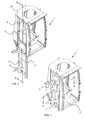
- Figure 3 shows an embodiment of the present work machine cab 1 as secured, by way of example, to a vertical pillar 2 of a loader in a truck, the figure showing just the vertical pillar with the work machine cab.
- This kind of a work machine cab may naturally be utilized in any kind of movable or immovable carriage as well as in said truck.
- the work machine cab in the form shown in the figure comprises a cabin space 3 furnished and equipped in the manner known per se, which will not be described in greater detail in this connection.
- This cabin space is surrounded, as usual, on six sides by wall, floor and roof structures, which are provided with necessary window surfaces and doors.
- the work machine cab 1 is arranged to be controllable in a translational movement, more precisely, in a substantially vertical linear movement, with a lifting unit 4 associated therewith.
- the linear movement is produced in relation to the carriage abutted on the work machine cab or a separate structure thereof, to which the lifting unit is attached with at least one securing means 5 in accordance with Figure 3 .
- These securing means are also visible in other figures, in which the work machine cab is shown detached from its operating environment.
- the lifting unit 4 comprises at least one guide bar 8 integrated with a side wall 7 as shown in the figures.
- guide bars consisting of, for instance, linear guide bars opposite one another as shown in Figure 6 .
- These linear guide bars preferably constitute part of the frame structure of the work machine cab 1, bracing the structure of the work machine cab, but just as well the linear guide bars may be attached to the frame structure of the work machine cab, thus contributing to the bracing of the structure of the work machine cab.
- the length of the guide bars is determined by the length of the desired linear movement.
- the guide bars extend from the floor of the work machine cab substantially to a window opening 9 to be provided in the side wall 7. Thus it is possible to maximize the light opening of the window, yet providing a sufficient lifting height for the work machine cab.
- control means 11 are arranged to move.
- control means comprises a means that extends substantially throughout the entire height of the side wall 7, whereby a sufficient rigidity is provided also at the extreme end of the vertical lifting movement of the work machine cab.
- the control means 11 may consist, for instance, of at least one slide connected to the linear guide bar 8, as best appears from Figures 1 and 2 . From this slide protrude securing means 5 wherewith the lifting unit 4 and the relating work machine cab 1 are attached to a loader, for instance.
- At least one actuator 12 whereby the mutual movement between the control means 11 and the guide bars 8 is provided, is arranged to control the movement of the lifting unit 4.
- This actuator advantageously comprises a pressure-medium-operated cylinder, and consequently it may be either a hydraulic or a pneumatic cylinder.
- the movement of the lifting unit is also produced by an electric motor, in which case the actuator 12 may comprise, for instance, a spindle motor or a step motor.
- the movement of the lifting unit may also be controlled by any systems known per se, which are not specified herein in detail. So, the actuator may control a cable arrangement, which for instance through a tackle arrangement, transfers the movement to the work machine cab.
- the actuator 12 controlling the movement of the lifting unit 4 extends from the lower edge 13 of the control means 11 in the lifting unit to the roof structures 14 of the work machine cab 1. Even though the figures show that the actuator extends over the window opening 9 of the side wall 7, nothing prevents the lifting unit from being provided with, for instance, two actuators mounted beside the guide bars 8, which actuators are closable in channels arranged in the side wall outside the window opening.
- the present work machine cab 1 operates as follows.
- the driver enters the cabin space 3.
- the actuator 12 controlling the operation of the lifting unit 4.
- the actuator moves the work machine cab vertically upwards along the control means 11.
- the control means is released from the channel 10 provided in the wall structure 7 of the work machine cab, the lifting-unit-side window opening 9 of the cabin space is cleared at the same time, which permits the driver to have a substantially unlimited visibility in all directions from the cabin space.
- the actuator stops automatically and the lifting unit is locked into place in this upper position.
- the locking may utilize, for instance, gripping means arranged in the slide constituting the control means, which gripping means, through their operation, prevent the cabin space from sliding downwardly.
- the lifting unit 4 is released to operate and the work machine cab 1 is controlled to descend towards its rest position, which is its lower position.
- the control means 11 is transferred along the guide bars 8 back to the channel 10 in the wall structure, retracting substantially for the entire length into the channel.
- the driver may step down from the cabin space.
Landscapes
- Engineering & Computer Science (AREA)
- Mechanical Engineering (AREA)
- Chemical & Material Sciences (AREA)
- Combustion & Propulsion (AREA)
- Transportation (AREA)
- Component Parts Of Construction Machinery (AREA)
Priority Applications (1)
| Application Number | Priority Date | Filing Date | Title |
|---|---|---|---|
| PL10164422T PL2261107T3 (pl) | 2009-06-01 | 2010-05-31 | Kabina maszyny roboczej |
Applications Claiming Priority (1)
| Application Number | Priority Date | Filing Date | Title |
|---|---|---|---|
| FI20095607A FI122191B (fi) | 2009-06-01 | 2009-06-01 | Työkoneohjaamo |
Publications (2)
| Publication Number | Publication Date |
|---|---|
| EP2261107A1 true EP2261107A1 (fr) | 2010-12-15 |
| EP2261107B1 EP2261107B1 (fr) | 2012-06-27 |
Family
ID=40825310
Family Applications (1)
| Application Number | Title | Priority Date | Filing Date |
|---|---|---|---|
| EP10164422A Active EP2261107B1 (fr) | 2009-06-01 | 2010-05-31 | Cabine de machine de travail |
Country Status (4)
| Country | Link |
|---|---|
| EP (1) | EP2261107B1 (fr) |
| ES (1) | ES2386617T3 (fr) |
| FI (1) | FI122191B (fr) |
| PL (1) | PL2261107T3 (fr) |
Cited By (3)
| Publication number | Priority date | Publication date | Assignee | Title |
|---|---|---|---|---|
| EP2671783A2 (fr) | 2012-06-08 | 2013-12-11 | Cargotec Finland Oy | Cabine pour grue |
| CN104973515A (zh) * | 2015-07-05 | 2015-10-14 | 范志甫 | 一种起重机多节安全操作室及其操作方法 |
| US20160083022A1 (en) * | 2013-05-08 | 2016-03-24 | BAE Systems Hägglunds Aktiebolag | Device for vehicle cab for a vehicle |
Citations (2)
| Publication number | Priority date | Publication date | Assignee | Title |
|---|---|---|---|---|
| US3252546A (en) * | 1964-01-30 | 1966-05-24 | Northwest Engineering Corp | Operator cab mounting |
| US3675966A (en) * | 1970-07-07 | 1972-07-11 | Int Harvester Co | Elevating compartment |
-
2009
- 2009-06-01 FI FI20095607A patent/FI122191B/fi active IP Right Grant
-
2010
- 2010-05-31 PL PL10164422T patent/PL2261107T3/pl unknown
- 2010-05-31 EP EP10164422A patent/EP2261107B1/fr active Active
- 2010-05-31 ES ES10164422T patent/ES2386617T3/es active Active
Patent Citations (2)
| Publication number | Priority date | Publication date | Assignee | Title |
|---|---|---|---|---|
| US3252546A (en) * | 1964-01-30 | 1966-05-24 | Northwest Engineering Corp | Operator cab mounting |
| US3675966A (en) * | 1970-07-07 | 1972-07-11 | Int Harvester Co | Elevating compartment |
Cited By (5)
| Publication number | Priority date | Publication date | Assignee | Title |
|---|---|---|---|---|
| EP2671783A2 (fr) | 2012-06-08 | 2013-12-11 | Cargotec Finland Oy | Cabine pour grue |
| EP2671783A3 (fr) * | 2012-06-08 | 2014-07-09 | Cargotec Finland Oy | Cabine pour grue |
| US20160083022A1 (en) * | 2013-05-08 | 2016-03-24 | BAE Systems Hägglunds Aktiebolag | Device for vehicle cab for a vehicle |
| US9630660B2 (en) * | 2013-05-08 | 2017-04-25 | BAE Systems Hägglunds Aktiebolag | Device for vehicle cab for a vehicle |
| CN104973515A (zh) * | 2015-07-05 | 2015-10-14 | 范志甫 | 一种起重机多节安全操作室及其操作方法 |
Also Published As
| Publication number | Publication date |
|---|---|
| EP2261107B1 (fr) | 2012-06-27 |
| FI122191B (fi) | 2011-10-14 |
| ES2386617T3 (es) | 2012-08-23 |
| PL2261107T3 (pl) | 2012-10-31 |
| FI20095607A0 (fi) | 2009-06-01 |
| FI20095607L (fi) | 2010-12-02 |
Similar Documents
| Publication | Publication Date | Title |
|---|---|---|
| EP3412830B1 (fr) | Machine de construction dotée d'un poste de commande et de protection d'accès | |
| US20150173984A1 (en) | Vehicle wheelchair lift | |
| EP2419318B1 (fr) | Fenêtre coulissante pour cabine d'un véhicule de service | |
| EP2261107B1 (fr) | Cabine de machine de travail | |
| US9797113B2 (en) | Motor grader implement valve layout for narrow front cab | |
| EP3489146B1 (fr) | Aéronef ayant un système de montage et démontage arrière de moteur et méthode de démontage d'un moteur par l'arrière | |
| EP2033932B1 (fr) | Chariot élévateur | |
| EP2511224B1 (fr) | Chariot de manutention pour rayonnage élevé, notamment chariot de commissionnement, doté d'un siège conducteur et d'accoudoirs latéraux | |
| EP2274193B1 (fr) | Cabine de commande et son procédé de fabrication, et véhicule d'exploitation minière | |
| DE10223684B4 (de) | Fahrzeugraum mit wenigstens einem, auf-und abwickelbaren, flexiblen Flächengebilde | |
| WO1991004221A1 (fr) | Amelioration apportee a un elevateur a fourche | |
| US20160130783A1 (en) | Motor Grader Implement Valve Layout for Narrow Front Cab | |
| FI95553B (fi) | Maanalaiseen käyttöön tarkoitetun liikkuvan koneen turvaohjaamojärjestely | |
| DE19802477A1 (de) | Türmodul mit außenliegendem Seil-Fensterheber | |
| DE19635751C1 (de) | Fahrerkabine für Erdbaumaschinen | |
| JP2006177117A (ja) | 建設機械のキャビンガード装置 | |
| EP1375224A2 (fr) | Ressort à gaz et verin pneumatique pour système élévateur à hauteur variable de dispositif enrouleur-derouleur | |
| US11724575B2 (en) | Self-propelled operating machine equipped with an improved cabin | |
| EP1123893B1 (fr) | Grue | |
| US10196098B2 (en) | Vehicle and a system for operating a work implement of a vehicle | |
| CN113816271A (zh) | 一种随车吊起重吊机驾驶室 | |
| WO2006076776A1 (fr) | Véhicule de mine souterraine avec cabine réglable en hauteur | |
| EP3388349A1 (fr) | Auvent d'une passerelle d'embarquement de passagers | |
| DE202023104498U1 (de) | Anordnung aufweisend einen anhebbaren und absenkbaren Zwischenboden für ein Kraftfahrzeug | |
| FI100394B (fi) | Työkone |
Legal Events
| Date | Code | Title | Description |
|---|---|---|---|
| PUAI | Public reference made under article 153(3) epc to a published international application that has entered the european phase |
Free format text: ORIGINAL CODE: 0009012 |
|
| AK | Designated contracting states |
Kind code of ref document: A1 Designated state(s): AL AT BE BG CH CY CZ DE DK EE ES FI FR GB GR HR HU IE IS IT LI LT LU LV MC MK MT NL NO PL PT RO SE SI SK SM TR |
|
| AX | Request for extension of the european patent |
Extension state: BA ME RS |
|
| 17P | Request for examination filed |
Effective date: 20110614 |
|
| GRAP | Despatch of communication of intention to grant a patent |
Free format text: ORIGINAL CODE: EPIDOSNIGR1 |
|
| GRAS | Grant fee paid |
Free format text: ORIGINAL CODE: EPIDOSNIGR3 |
|
| RIN1 | Information on inventor provided before grant (corrected) |
Inventor name: PAETSI, ESA |
|
| GRAA | (expected) grant |
Free format text: ORIGINAL CODE: 0009210 |
|
| AK | Designated contracting states |
Kind code of ref document: B1 Designated state(s): AL AT BE BG CH CY CZ DE DK EE ES FI FR GB GR HR HU IE IS IT LI LT LU LV MC MK MT NL NO PL PT RO SE SI SK SM TR |
|
| REG | Reference to a national code |
Ref country code: GB Ref legal event code: FG4D |
|
| REG | Reference to a national code |
Ref country code: CH Ref legal event code: EP |
|
| REG | Reference to a national code |
Ref country code: AT Ref legal event code: REF Ref document number: 564029 Country of ref document: AT Kind code of ref document: T Effective date: 20120715 |
|
| REG | Reference to a national code |
Ref country code: IE Ref legal event code: FG4D |
|
| REG | Reference to a national code |
Ref country code: ES Ref legal event code: FG2A Ref document number: 2386617 Country of ref document: ES Kind code of ref document: T3 Effective date: 20120823 Ref country code: DE Ref legal event code: R096 Ref document number: 602010002013 Country of ref document: DE Effective date: 20120823 |
|
| REG | Reference to a national code |
Ref country code: SE Ref legal event code: TRGR |
|
| PG25 | Lapsed in a contracting state [announced via postgrant information from national office to epo] |
Ref country code: NO Free format text: LAPSE BECAUSE OF FAILURE TO SUBMIT A TRANSLATION OF THE DESCRIPTION OR TO PAY THE FEE WITHIN THE PRESCRIBED TIME-LIMIT Effective date: 20120927 Ref country code: LT Free format text: LAPSE BECAUSE OF FAILURE TO SUBMIT A TRANSLATION OF THE DESCRIPTION OR TO PAY THE FEE WITHIN THE PRESCRIBED TIME-LIMIT Effective date: 20120627 Ref country code: FI Free format text: LAPSE BECAUSE OF FAILURE TO SUBMIT A TRANSLATION OF THE DESCRIPTION OR TO PAY THE FEE WITHIN THE PRESCRIBED TIME-LIMIT Effective date: 20120627 |
|
| REG | Reference to a national code |
Ref country code: PL Ref legal event code: T3 |
|
| REG | Reference to a national code |
Ref country code: NL Ref legal event code: VDEP Effective date: 20120627 |
|
| REG | Reference to a national code |
Ref country code: LT Ref legal event code: MG4D Effective date: 20120627 |
|
| PG25 | Lapsed in a contracting state [announced via postgrant information from national office to epo] |
Ref country code: HR Free format text: LAPSE BECAUSE OF FAILURE TO SUBMIT A TRANSLATION OF THE DESCRIPTION OR TO PAY THE FEE WITHIN THE PRESCRIBED TIME-LIMIT Effective date: 20120627 Ref country code: GR Free format text: LAPSE BECAUSE OF FAILURE TO SUBMIT A TRANSLATION OF THE DESCRIPTION OR TO PAY THE FEE WITHIN THE PRESCRIBED TIME-LIMIT Effective date: 20120928 Ref country code: LV Free format text: LAPSE BECAUSE OF FAILURE TO SUBMIT A TRANSLATION OF THE DESCRIPTION OR TO PAY THE FEE WITHIN THE PRESCRIBED TIME-LIMIT Effective date: 20120627 Ref country code: SI Free format text: LAPSE BECAUSE OF FAILURE TO SUBMIT A TRANSLATION OF THE DESCRIPTION OR TO PAY THE FEE WITHIN THE PRESCRIBED TIME-LIMIT Effective date: 20120627 |
|
| PG25 | Lapsed in a contracting state [announced via postgrant information from national office to epo] |
Ref country code: BE Free format text: LAPSE BECAUSE OF FAILURE TO SUBMIT A TRANSLATION OF THE DESCRIPTION OR TO PAY THE FEE WITHIN THE PRESCRIBED TIME-LIMIT Effective date: 20120627 Ref country code: SK Free format text: LAPSE BECAUSE OF FAILURE TO SUBMIT A TRANSLATION OF THE DESCRIPTION OR TO PAY THE FEE WITHIN THE PRESCRIBED TIME-LIMIT Effective date: 20120627 Ref country code: EE Free format text: LAPSE BECAUSE OF FAILURE TO SUBMIT A TRANSLATION OF THE DESCRIPTION OR TO PAY THE FEE WITHIN THE PRESCRIBED TIME-LIMIT Effective date: 20120627 Ref country code: RO Free format text: LAPSE BECAUSE OF FAILURE TO SUBMIT A TRANSLATION OF THE DESCRIPTION OR TO PAY THE FEE WITHIN THE PRESCRIBED TIME-LIMIT Effective date: 20120627 Ref country code: CZ Free format text: LAPSE BECAUSE OF FAILURE TO SUBMIT A TRANSLATION OF THE DESCRIPTION OR TO PAY THE FEE WITHIN THE PRESCRIBED TIME-LIMIT Effective date: 20120627 Ref country code: CY Free format text: LAPSE BECAUSE OF FAILURE TO SUBMIT A TRANSLATION OF THE DESCRIPTION OR TO PAY THE FEE WITHIN THE PRESCRIBED TIME-LIMIT Effective date: 20120627 Ref country code: IS Free format text: LAPSE BECAUSE OF FAILURE TO SUBMIT A TRANSLATION OF THE DESCRIPTION OR TO PAY THE FEE WITHIN THE PRESCRIBED TIME-LIMIT Effective date: 20121027 |
|
| PG25 | Lapsed in a contracting state [announced via postgrant information from national office to epo] |
Ref country code: PT Free format text: LAPSE BECAUSE OF FAILURE TO SUBMIT A TRANSLATION OF THE DESCRIPTION OR TO PAY THE FEE WITHIN THE PRESCRIBED TIME-LIMIT Effective date: 20121029 Ref country code: IT Free format text: LAPSE BECAUSE OF FAILURE TO SUBMIT A TRANSLATION OF THE DESCRIPTION OR TO PAY THE FEE WITHIN THE PRESCRIBED TIME-LIMIT Effective date: 20120627 |
|
| PG25 | Lapsed in a contracting state [announced via postgrant information from national office to epo] |
Ref country code: NL Free format text: LAPSE BECAUSE OF FAILURE TO SUBMIT A TRANSLATION OF THE DESCRIPTION OR TO PAY THE FEE WITHIN THE PRESCRIBED TIME-LIMIT Effective date: 20120627 |
|
| PG25 | Lapsed in a contracting state [announced via postgrant information from national office to epo] |
Ref country code: DK Free format text: LAPSE BECAUSE OF FAILURE TO SUBMIT A TRANSLATION OF THE DESCRIPTION OR TO PAY THE FEE WITHIN THE PRESCRIBED TIME-LIMIT Effective date: 20120627 |
|
| PLBE | No opposition filed within time limit |
Free format text: ORIGINAL CODE: 0009261 |
|
| STAA | Information on the status of an ep patent application or granted ep patent |
Free format text: STATUS: NO OPPOSITION FILED WITHIN TIME LIMIT |
|
| 26N | No opposition filed |
Effective date: 20130328 |
|
| REG | Reference to a national code |
Ref country code: DE Ref legal event code: R097 Ref document number: 602010002013 Country of ref document: DE Effective date: 20130328 |
|
| PG25 | Lapsed in a contracting state [announced via postgrant information from national office to epo] |
Ref country code: BG Free format text: LAPSE BECAUSE OF FAILURE TO SUBMIT A TRANSLATION OF THE DESCRIPTION OR TO PAY THE FEE WITHIN THE PRESCRIBED TIME-LIMIT Effective date: 20120927 |
|
| PG25 | Lapsed in a contracting state [announced via postgrant information from national office to epo] |
Ref country code: MC Free format text: LAPSE BECAUSE OF FAILURE TO SUBMIT A TRANSLATION OF THE DESCRIPTION OR TO PAY THE FEE WITHIN THE PRESCRIBED TIME-LIMIT Effective date: 20120627 |
|
| REG | Reference to a national code |
Ref country code: IE Ref legal event code: MM4A |
|
| PG25 | Lapsed in a contracting state [announced via postgrant information from national office to epo] |
Ref country code: IE Free format text: LAPSE BECAUSE OF NON-PAYMENT OF DUE FEES Effective date: 20130531 |
|
| REG | Reference to a national code |
Ref country code: CH Ref legal event code: PL |
|
| GBPC | Gb: european patent ceased through non-payment of renewal fee |
Effective date: 20140531 |
|
| PG25 | Lapsed in a contracting state [announced via postgrant information from national office to epo] |
Ref country code: LI Free format text: LAPSE BECAUSE OF NON-PAYMENT OF DUE FEES Effective date: 20140531 Ref country code: CH Free format text: LAPSE BECAUSE OF NON-PAYMENT OF DUE FEES Effective date: 20140531 |
|
| PG25 | Lapsed in a contracting state [announced via postgrant information from national office to epo] |
Ref country code: MT Free format text: LAPSE BECAUSE OF FAILURE TO SUBMIT A TRANSLATION OF THE DESCRIPTION OR TO PAY THE FEE WITHIN THE PRESCRIBED TIME-LIMIT Effective date: 20120627 |
|
| PG25 | Lapsed in a contracting state [announced via postgrant information from national office to epo] |
Ref country code: SM Free format text: LAPSE BECAUSE OF FAILURE TO SUBMIT A TRANSLATION OF THE DESCRIPTION OR TO PAY THE FEE WITHIN THE PRESCRIBED TIME-LIMIT Effective date: 20120627 Ref country code: GB Free format text: LAPSE BECAUSE OF NON-PAYMENT OF DUE FEES Effective date: 20140531 |
|
| PG25 | Lapsed in a contracting state [announced via postgrant information from national office to epo] |
Ref country code: TR Free format text: LAPSE BECAUSE OF FAILURE TO SUBMIT A TRANSLATION OF THE DESCRIPTION OR TO PAY THE FEE WITHIN THE PRESCRIBED TIME-LIMIT Effective date: 20120627 |
|
| PG25 | Lapsed in a contracting state [announced via postgrant information from national office to epo] |
Ref country code: LU Free format text: LAPSE BECAUSE OF NON-PAYMENT OF DUE FEES Effective date: 20130531 Ref country code: MK Free format text: LAPSE BECAUSE OF FAILURE TO SUBMIT A TRANSLATION OF THE DESCRIPTION OR TO PAY THE FEE WITHIN THE PRESCRIBED TIME-LIMIT Effective date: 20120627 Ref country code: HU Free format text: LAPSE BECAUSE OF FAILURE TO SUBMIT A TRANSLATION OF THE DESCRIPTION OR TO PAY THE FEE WITHIN THE PRESCRIBED TIME-LIMIT; INVALID AB INITIO Effective date: 20100531 |
|
| REG | Reference to a national code |
Ref country code: FR Ref legal event code: PLFP Year of fee payment: 7 |
|
| REG | Reference to a national code |
Ref country code: FR Ref legal event code: PLFP Year of fee payment: 8 |
|
| REG | Reference to a national code |
Ref country code: FR Ref legal event code: PLFP Year of fee payment: 9 |
|
| PG25 | Lapsed in a contracting state [announced via postgrant information from national office to epo] |
Ref country code: AL Free format text: LAPSE BECAUSE OF FAILURE TO SUBMIT A TRANSLATION OF THE DESCRIPTION OR TO PAY THE FEE WITHIN THE PRESCRIBED TIME-LIMIT Effective date: 20120627 |
|
| PGFP | Annual fee paid to national office [announced via postgrant information from national office to epo] |
Ref country code: DE Payment date: 20250520 Year of fee payment: 16 Ref country code: PL Payment date: 20250505 Year of fee payment: 16 |
|
| PGFP | Annual fee paid to national office [announced via postgrant information from national office to epo] |
Ref country code: ES Payment date: 20250611 Year of fee payment: 16 |
|
| PGFP | Annual fee paid to national office [announced via postgrant information from national office to epo] |
Ref country code: FR Payment date: 20250516 Year of fee payment: 16 |
|
| PGFP | Annual fee paid to national office [announced via postgrant information from national office to epo] |
Ref country code: AT Payment date: 20250520 Year of fee payment: 16 |
|
| PGFP | Annual fee paid to national office [announced via postgrant information from national office to epo] |
Ref country code: SE Payment date: 20250520 Year of fee payment: 16 |