EP2274193B1 - Cabine de commande et son procédé de fabrication, et véhicule d'exploitation minière - Google Patents
Cabine de commande et son procédé de fabrication, et véhicule d'exploitation minière Download PDFInfo
- Publication number
- EP2274193B1 EP2274193B1 EP09742205A EP09742205A EP2274193B1 EP 2274193 B1 EP2274193 B1 EP 2274193B1 EP 09742205 A EP09742205 A EP 09742205A EP 09742205 A EP09742205 A EP 09742205A EP 2274193 B1 EP2274193 B1 EP 2274193B1
- Authority
- EP
- European Patent Office
- Prior art keywords
- control cabin
- inner module
- module
- space
- cabin space
- Prior art date
- Legal status (The legal status is an assumption and is not a legal conclusion. Google has not performed a legal analysis and makes no representation as to the accuracy of the status listed.)
- Not-in-force
Links
Images


Classifications
-
- B—PERFORMING OPERATIONS; TRANSPORTING
- B62—LAND VEHICLES FOR TRAVELLING OTHERWISE THAN ON RAILS
- B62D—MOTOR VEHICLES; TRAILERS
- B62D33/00—Superstructures for load-carrying vehicles
- B62D33/06—Drivers' cabs
- B62D33/0617—Drivers' cabs for tractors or off-the-road vehicles
Definitions
- the invention relates to a mining vehicle control cabin which is formed of a control cabin space and at least one inner module.
- the inner module is arranged as one piece in the control cabin space which forms a shell for protecting an operator.
- the invention further relates to a method of manufacturing a control cabin, and to a mining vehicle equipped with such a control cabin.
- Mining vehicles such as loading vehicles, dumpers, rock drilling rigs and the like, include a control cabin in which the controls of the vehicle are provided and which protects a driver of the vehicle e.g. against pieces of falling rock, dust, and noise.
- the control cabin protects the driver during collisions and in the event of a roll-over.
- JP-A-2003/056008 discloses a protective control cabin of a digging machine. Its disclosure forms the basis for the preamble features of claims 1.
- a control cabin is a separately manufactured module which, during the assembly of the mining vehicle, is fastened to a control cabin site provided on a carrier. Different vehicles require different control cabins, which causes high costs.
- modular control cabins provided with a shell part and an inner part arranged therein have been developed.
- the inner part of a modular control cabin is fastened to the shell part, and the shell part is by means of dampers fastened to the carrier of the vehicle. It has been noted that the known control cabins are inadequate in terms of manufacture and vibrodamping.
- the main object of the invention is to provide a novel and improved mining vehicle control cabin, a method of manufacturing the same and, further, a mining vehicle equipped with such a control cabin.
- a control cabin according to the invention is characterized in that the inner module comprises damping members which enable it to be engaged in place in the control cabin space with no rigid engagement with the surrounding structures.
- a method according to the invention is characterized by pro-35 viding the inner module with damping members; and arranging the inner module in the control cabin space with no rigid engagement with the surrounding structures.
- a mining vehicle according to the invention is characterized in that the inner module is arranged in the control cabin space and supported in place by means of damping members with no rigid engagement with the surrounding structures.
- control cabin space constitutes a shell for protecting the operator.
- One or more inner modules are arranged in the control cabin space as one piece and supported in place by means of damping members such that they are not rigidly engaged with the protective shell or a protective structure defining the control cabin space, such as the carrier or a roll cage of the vehicle, nor with other surfaces or structures surrounding the control cabin space.
- An advantage of the invention is that the relatively light-weight and small inner module can be isolated effectively from the vibration of the carrier by means of the damping members. Further, it is relatively easy and quick to replace the mere inner part e.g. in situations where the working environment of the operator is to be changed later or when the properties of the vehicle are changed and new control equipment is needed.
- the control cabin may thus be updated by replacing the inner module only. It is not usually necessary to update the control cabin space, i.e. the shell protecting the operator.
- the inner module has standard dimensions irrespective of the vehicle.
- the dimensioning of the control cabin space is carried out vehicle-specifically, taking the space reserved for the control cabin site into account. This enables the control cabin space to be designed taking aspects associated with the use, service and appearance of each vehicle into account.
- the structure of the roll cage or a corresponding safety structure may be designed taking into account the layout of the carrier, the components and devices provided on the carrier as well as the support points to which the roll cage may be fastened in a reliable manner.
- the inner module in turn, may be of a standard component type so that it is also suitable for use in vehicles different from one another.
- an inner module which may be installed in a rock drilling rig, loading vehicle, transport vehicle or in any other mining vehicle.
- the physical structure of the inner module may thus be constant, and it will suffice that the controls are adjusted or programmed as required by each vehicle.
- control cabin comprises at least two inner modules. It is possible to arrange at least one first inner module and one or more second inner modules inside the large control cabin space.
- the first inner module comprises at least a frame, an operator support, such as a seat, and at least one set of controls.
- the second inner module may comprise a frame, another set of controls, and a display device. In some cases, it may be easier to install more than one inner module than only one large module.
- an idea of an embodiment is that the inner module is engaged directly with the carrier of the vehicle by means of the damping members.
- the damping members are arranged between the frame of the inner module and the carrier.
- an idea of an embodiment is that the inner module has no physical contact whatsoever with the surfaces of the control cabin space, the support structures or the like.
- an idea of an embodiment is that the inner module is engaged with the surfaces of the control cabin space, the support structures or the like by means of the damping members.
- the roof of the control cabin space may be opened and closed, enabling the inner module to be installed as one piece into its place in the control cabin space through the open upper part of the control cabin space and, correspondingly, to be lifted as one piece out of the control cabin space.
- one side wall of the control cabin space may be opened and closed or, alternatively, a door provided in the control cabin space is dimensioned to be sufficiently large so as to enable the inner module to be installed as one piece into its place in the control cabin space through a lateral opening and, correspondingly, to be removed as one piece out of the control cabin space by a lateral movement.
- the inner module comprises, at a predetermined position, a coupling point for all connections of the control cabin.
- the electric, pressure medium and data connections to be supplied to the control cabin are collected in one standard place in the inner module.
- the control cabin space is provided with a second coupling point at the same location, whereby when the inner module is arranged in the control cabin space, the coupling points settle close to one another, so that they are easy to interconnect by suitable connecting leads or corresponding connecting members.
- This embodiment makes the modules easier to design and assemble.
- it makes an inner module simpler to replace by a new one, if necessary, when the connections are located at a predetermined coupling point.
- the coupling points may be provided with suitable quick coupling members, which makes the inner module even quicker to install and replace later, if necessary.
- the inner module comprises at least one display device.
- control cabin space comprises at least one control panel.
- control cabin space is formed as an integrated part of the frame structure of the carrier of the vehicle.
- the control cabin space may be defined by side plates which belong to the carrier and which may be dimensioned to extend higher in the vertical direction at the control cabin than at other sections.
- the side plates constitute a safety structure to protect the operator.
- control cabin comprises a shell module inside which one or more inner modules are arranged.
- the shell module is pre-assembled and it is by means of fastening members fastened rigidly to the carrier of the vehicle such that the safety structure of the shell module is capable of receiving vertical loads required of a roll cage.
- the shell module thus forms a control cabin space into which the inner module is arranged as one piece.
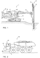
- Figure 1 shows a rock drilling rig 1 comprising a movable carrier 2 with one or more booms 3 arranged therein.
- the boom 3 is provided with a drilling unit 4 which comprises a feed beam 5 which supports a rock drill machine 6 while it is moved.
- the carrier 2 carries a motor 7, a hydraulic pump 8, a flushing and dust collecting system 9 as well as a control cabin 10 necessitated by the rock drilling rig 1.
- a control cabin site 11 is reserved on the carrier 2 for receiving the control cabin 10.
- the control cabin 10 consists of a control cabin space and at least one separately manufactured module, as will be shown in greater detail later in this application.
- the rock drilling rig 1 is an example of a mining vehicle referred to in the present application.
- FIG. 2 shows a transport vehicle 12, i.e. a dumper, which is another example of a mining vehicle.
- the transport vehicle 12 also comprises a movable carrier 2 provided with a control cabin site 11 wherein a modular control cabin 10 according to the invention is arranged.
- the appearance and dimensions of the control cabin 10 may differ greatly. According to the idea of the invention, however, it is possible to use even identical inner modules in mining vehicles different from one another.
- a shell module of the control cabin 10 or another structure forming the control cabin space may be provided taking e.g. the available space, i.e. the shape and dimensions of the control cabin site, the protection needs of the control cabin as well as the esthetic aspects into account.
- Yet another mining vehicle is a loading vehicle whose movable carrier is equipped with a loading bucket.
- FIG 3 shows an inner module 13 which may be pre-assembled in a separate stage so that it may be installed as one entity in its place inside a shell module 14, as can be seen in Figure 5 .
- the inner module 13 comprises a frame 15, which may be e.g. a plate-like piece to which components belonging to the inner module may be fastened.
- the frame 15 is a bottom plate having a seat 16 supported against the upper surface side thereof.
- the inner module 13 may further comprise a display device 17, which may be supported by suitable support members against the frame 15 or structures of the seat 16.
- the inner module may comprise another operator support.
- the inner module 13 may still further comprise controls 18, such as one or more pedals 18a, a pointing device 18b, such as a joystick, trackball mouse, keypad or the like.
- the pointing device 18b and various switches may be arranged in one or more arm rests or a corresponding panel so that they are ergonomically available to the operator.
- the inner module 13 may still further comprise one or more control units 19 which may comprise a computer or a corresponding control device.
- the inner module 13 may be provided with a coupling point 20 whose location may be standard in all modules of the control cabin.
- the coupling point 20 is equipped with coupling members by means of which the controls 18, the control unit 19, the display device of the inner module 13 as well as possible other instruments contained in the inner unit are connectable with the electric, pressure medium and data transfer lines of the carrier.
- the inner module 13 comprises no roll cage or the like but is a light-weight and easily installable inner part which has a considerable influence on the working environment and ergonomics of the operator as well as on the functionality of the control cabin.
- the inner module 13 is equipped with one or more damping members 21 which enable it to be supported in place against the structures defining the control cabin space in a shock and vibration damping manner.
- the damping member 21 may comprise a mechanical spring 21 a, or it may be a pressure medium operated spring member 21 b. Further, a spring member 21 c based on an elastic material may be used. In addition to a flexible structure, the damping members 21 may also comprise return motion damping. The type and number of damping members 21 may be selected as necessary.
- One or more damping members may be arranged to support the inner module higher in the vertical direction, which enables a better stability to be achieved.
- the shell module 14 shown in Figure 4 comprises a roll cage 22, which may be formed of tubular beams or the like or, alternatively, the roll cage is formed of sufficiently strong wall panels.
- a roll cage 22 generally refers to a structure which protects the operator in the event of an accident.
- a roll cage has to be strong enough to withstand a roll-over of the vehicle, i.e. it has to be a ROPS (Roll Over Protective Structure) protected structure.
- ROPS Roll Over Protective Structure
- the shell module 14 also forms the visible outer and inner surfaces of the control cabin 10.
- the shell module 14 may be provided with a window 23, a roof 24, side panels 25, and at least one door 26, which can be seen in Figure 2 .
- the side panels 25 may be windows 27.
- the roof 24 may be fastened detachably or it may be hinged by its one edge so that it may be opened in a manner shown in Figure 5 to enable the inner module 13 to be installed.
- a side panel forming one side of the shell module 14 may be arranged easily detachably, or it may be hinged so that it may be opened easily, in which case the inner module 13 may be installed inside the shell module 14 in a lateral direction.
- An openable side panel is illustrated in dashed line 28 in Figure 4 .
- the shell module 14 may comprise fastening flanges 29, fastening loops or corresponding fastening members by means of which it may be reliably fastened to the control cabin site 11, which may also be equipped with corresponding fastening members 30, provided on the carrier 2.
- the fastening members 29, 30 may be interconnected by a bolt joint, a fastening pin or some suitable quick-fastening device.
- the shell module 14 is fastened to the carrier 2 by welding.
- the shell module 14 is fastened to the carrier 2 by using a strong physical joint.
- the shell module 14 may be equipped with one or more control panels 31, which may include switches, control devices 32, gauges, and a display device 33.
- the control panel 31 may be provided with vehicle-specific equipment and controls while the inner module 13 comprises standard controls and control devices. Further, the shell module 14 may have a coupling point 34 in a manner similar to that in connection with the inner module 13.
- Figure 5 illustrates installation of the inner module 13 into a space 35 defined by the shell module 14.
- the roof 24 may be opened with respect to hinging or it may be detached completely for the duration of the installation of the inner module 13.
- installation direction A is vertical.
- the damping members 21 of the inner module 13 may be supported directly against the control cabin site on the carrier 2 since the shell module 14 has no floor at the inner module 13. After the inner module 13 has been supported in place, the couplings of electric, data and pressure medium lines may be carried out at the coupling points 20, 34.
- FIG. 6 shows another control cabin 10 whose shell module 14 differs from the embodiment shown in Figures 4 and 5 .
- the shape of the shell module 14 is influenced by the shapes of components 36 surrounding the control cabin site 11.
- the shell module 14 comprises a floor 37, in which case the inner module 13 is supported against the floor 37 by means of the damping members 21.
- installation direction A is horizontal.
- the door in the shell module 14 may be dimensioned such that the inner module 13 may be arranged through the door into the control cabin space 35 defined by the shell module 14.
- a side panel 25a may be opened for installation.
- Figure 7 is a top view showing a control cabin 10 wherein two inner modules 13a, 13b have been arranged in the control cabin space 35 defined by the shell module 14.
- At least a first inner module 13a comprises a seat and controls, as shown in the previous figures.
- a second inner module 13b may also comprise a seat and necessary controls or, alternatively, the second inner module may only comprise additional controls, an additional control panel, and an additional display.
- the shell element 14 is formed of side panels 25 and a roof that are strong enough to provide a sufficient roll cage 22 against accidents.
- Figure 8 shows an inner module 13 equipped with an active damping system.
- the system comprises one or more sensors 40 for identifying movements of the inner module 13 and/or the carrier 2 of the vehicle.
- the sensor 40 may be e.g. an acceleration sensor which very quickly detects if the vehicle is driven e.g. onto an inclined surface, into a pit or to another point causing inclination or vibration.
- a control unit 41 included in the damping system is provided with a control strategy according to which it controls one or more active damping elements 42 to generate a necessary counter-movement in order to damp the inclination or vibration detected by the sensor 40.
- the active damping element 42 may be e.g. a pressure medium cylinder. As can be seen in the figure, at least one damping element may be supported against the structure of the inner module higher in the vertical direction, which enables stability to be achieved more easily.
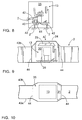
- Figures 9 and 10 show a control cabin which is different from the previous constructions and which comprises no separate shell module but the control cabin space 35 is formed directly in the structure of the carrier 2.
- the frame structure of the carrier 2 may comprise two mutually space-apart side plates 43a, 43b between which the control cabin space 35 is provided. If the carrier 2 is particularly narrow, it is possible to arrange the side plates 43a, 43b more widely spaced apart at the control cabin than at other sections. Further, the side plates 43a, 43b may be dimensioned to extend a greater distance upwards in the vertical direction at the control cabin, in which case the side plates 43a, 43b constitute the necessary roll cage.
- the control cabin space 35 may also be defined by transverse walls 44 or corresponding support structures between the side plates 43a, 43b.
- the shell of the control cabin space 35 may comprise an openable and closable roof 24 through which the inner module 13 may be arranged in the control cabin space 35.
- the shell of the control cabin space 35 may further comprise the necessary other shell panels, a window 23, and a door 26.
- the control cabin space 35 may be provided with a fixed control panel 31 which may be equipped with the basic gauges and controls of the vehicle. The devices, gauges, displays, controls and other equipment which are possibly to be updated later and which influence the working environment of the operator may be arranged in the replaceable inner module 13.
- the features disclosed in the present application may be used as such, irrespective of other features.
- the features set forth in the present application may be combined so as to provide different combinations.
Landscapes
- Engineering & Computer Science (AREA)
- Chemical & Material Sciences (AREA)
- Combustion & Propulsion (AREA)
- Transportation (AREA)
- Mechanical Engineering (AREA)
- Body Structure For Vehicles (AREA)
Claims (16)
- Cabine de commande d'un véhicule d'exploitation minière, comprenant
un espace de cabine de commande (35) défini par des surfaces agencées de façon à former une enveloppe de protection qui entoure un conducteur ; et
au moins un module intérieur (13), qui est agencé dans l'espace de cabine de commande (35), et qui comprend des éléments d'amortissement (21) au moyen desquels il est mis en prise en place dans l'espace de cabine de commande (35) sans mise en prise rigide avec les structures environnantes ;
caractérisée en ce que
le module intérieur (13) est un élément préassemblé ;
le module intérieur (13) est agencé d'un seul tenant dans l'espace de cabine de commande (35) ;
le module intérieur (13) comprend un premier point d'accouplement (20) et l'espace de cabine de commande (35) comprend un second point d'accouplement (34) pour toutes les connexions des moyens électriques et de pression de la cabine de commande (10) ;
le premier point d'accouplement (20) et le second point d'accouplement (34) sont agencés à proximité l'un de l'autre ;
et dans laquelle au moins une partie d'enveloppe de l'espace de cabine de commande (35) peut être ouverte et fermée, grâce à quoi le module intérieur (13) peut être installé d'un seul tenant à sa place dans l'espace de cabine de commande (35) et, réciproquement, il peut être retiré d'un seul tenant hors de l'espace de cabine de commande (35). - Cabine de commande selon la revendication 1, caractérisée en ce que
l'espace de cabine de commande (35) fait partie intégrante de la structure de châssis (2) du véhicule. - Cabine de commande selon la revendication 2, caractérisée en ce que
l'espace de cabine de commande (35) est défini sur au moins deux côtés par des plaques latérales (43a, 43b) incluses dans une structure de bâti du châssis (2) du véhicule, les plaques latérales (43a, 43b) formant également une cage de retournement de la cabine de commande (10). - Cabine de commande selon la revendication 1, caractérisée en ce que
la cabine de commande (10) comprend un module d'enveloppe (14) qui est préassemblé et séparé du châssis (2) du véhicule ;
le module d'enveloppe (14) englobe l'espace de cabine de commande (35) ; et
le module d'enveloppe (14) comprend des éléments de fixation (29) destinés à le fixer de manière rigide au châssis (2) du véhicule. - Cabine de commande selon la revendication 4, caractérisée en ce que
le module d'enveloppe (14) comprend au moins une cage de retournement (22), des panneaux latéraux (25), une porte (26), une fenêtre (23), et un toit (24). - Cabine de commande selon l'une quelconque des revendications précédentes, caractérisée en ce que
le module intérieur (13) comprend au moins une partie de bâti (15), un support de conducteur (16), et au moins un ensemble de commandes (18). - Cabine de commande selon l'une quelconque des revendications précédentes, caractérisée en ce que
le module intérieur (13) présente des dimensions normalisées indépendantes du véhicule ; et
les dimensions de l'espace de cabine de commande (35) dépendent principalement du véhicule. - Cabine de commande selon l'une quelconque des revendications précédentes, caractérisée en ce que
l'espace de cabine de commande (35) est doté d'au moins deux modules intérieurs (13a, 13b). - Cabine de commande selon l'une quelconque des revendications précédentes, caractérisée en ce que
le module intérieur (13) est mis en prise directement avec le châssis (2) du véhicule au moyen des éléments d'amortissement (21). - Cabine de commande selon l'une quelconque des revendications précédentes 4 à 9, caractérisée en ce que
le module intérieur (13) est mis en prise avec le module d'enveloppe (14) au moyen des éléments d'amortissement (21). - Cabine de commande selon l'une quelconque des revendications précédentes, caractérisée en ce que
l'espace de cabine de commande (35) comprend au moins un panneau de commande (31). - Cabine de commande selon l'une quelconque des revendications précédentes, caractérisée en ce que
le module intérieur (13) est doté d'un système d'amortissement actif qui comprend : au moins un capteur (40) pour identifier des déplacements du module intérieur (13) ou du châssis (2) du véhicule, une unité de commande du système d'amortissement (41) et au moins une élément d'amortissement actif (42) ; et
l'unité de commande du système d'amortissement (41) est agencée de façon à commander le au moins un élément d'amortissement (42) et à amortir les déplacements du module intérieur (13) de manière active sur la base d'informations reçues en provenance du capteur (40). - Procédé de fabrication d'une cabine de commande d'un véhicule d'exploitation minière, le procédé comprenant
la formation d'au moins un module intérieur (13) ;
la formation d'un espace de cabine de commande (35) qui comprend une enveloppe de protection constituant les surfaces extérieures de la cabine de commande (10) ;
la fourniture au module intérieur (13) d'éléments d'amortissement (21) ; et
le fait de supporter le module intérieur (13) au moyen des éléments d'amortissement (21) dans l'espace de cabine de commande (35) sans mise en prise rigide avec les structures environnantes ;
caractérisé par
le préassemblage du module intérieur (13) séparément par rapport à l'espace de cabine de commande (35) ;
l'agencement du module intérieur (13) d'un seul tenant dans l'espace de cabine de commande (35) à partir d'une direction d'installation (A) à travers une partie pouvant être ouverte et fermée de l'enveloppe de protection ;
la fourniture au module intérieur (13) d'un premier point d'accouplement (20) et la fourniture à l'espace de cabine de commande (35) d'un second point d'accouplement (34) pour toutes les connexions des moyens électriques et de pression de la cabine de commande (10) ;
l'agencement du premier point d'accouplement (20) et du second point d'accouplement (34) à proximité l'un de l'autre ; et
la connexion du premier point d'accouplement (20) et du second point d'accouplement (34) l'un à l'autre. - Procédé selon la revendication 13, caractérisé par
la formation de la cabine de contrôle (10) d'au moins deux modules préassemblés, à savoir un module d'enveloppe (14) et le module intérieur (13) ;
la formation de l'espace de cabine de commande (35) sur la base de l'espace disponible et de la forme d'un emplacement de cabine de commande (11) disposé sur un châssis (2) ;
le fait d'équiper le module d'enveloppe (14) avec au moins une cage de retournement (22) et avec une enveloppe extérieure constituant les surfaces extérieures de la cabine de commande (10) ;
le fait d'équiper en outre le module d'enveloppe (14) avec des éléments de fixation (29) et de fixer le module d'enveloppe (14) de manière rigide au châssis (2) du véhicule ; et
le fait d'équiper au moins un module intérieur (13) avec au moins une partie de bâti (15), un support de conducteur (16) et au moins un ensemble de commandes (18). - Procédé selon la revendication 13, caractérisé par
la formation de l'espace de cabine de commande (35) dans la structure de bâti fixe du châssis (2) du véhicule. - Véhicule d'exploitation minière comprenant
un châssis mobile (2) ;
au moins un dispositif d'exploitation minière (4) ;
une cabine de commande (10) agencée sur le châssis (2) à un emplacement de cabine de commande (11) attribué à la cabine de commande (10); et dans lequel
la cabine de commande (10) comprend au moins un module intérieur (13) et un espace de cabine de commande (35) ; et
le module intérieur (13) est supporté en place dans l'espace de cabine de commande (35) au moyen d'éléments d'amortissement (21) sans mise en prise rigide avec les structures environnantes ;
caractérisée en ce que
le module intérieur (13) est un élément préassemblé qui est agencé d'un seul tenant dans l'espace de cabine de commande ;
l'espace de cabine de commande est doté d'une enveloppe de protection présentant au moins une partie pouvant être ouverte et fermée à travers laquelle le module intérieur est installé à sa place ;
le module intérieur (13) comprend un premier point d'accouplement (20) et l'espace de cabine de commande (35) comprend un second point d'accouplement (34) pour toutes les connexions des moyens électriques et de pression de la cabine de commande (10) ; et
le premier point d'accouplement (20) et le second point d'accouplement (34) sont agencés à proximité l'un de l'autre.
Priority Applications (1)
| Application Number | Priority Date | Filing Date | Title |
|---|---|---|---|
| PL09742205T PL2274193T3 (pl) | 2008-05-09 | 2009-05-07 | Kabina sterownicza, sposób jej produkcji i pojazd górniczy |
Applications Claiming Priority (2)
| Application Number | Priority Date | Filing Date | Title |
|---|---|---|---|
| FI20085434A FI124140B (fi) | 2008-05-09 | 2008-05-09 | Ohjaamo ja menetelmä sen valmistamiseksi sekä kaivosajoneuvo |
| PCT/FI2009/050370 WO2009136005A1 (fr) | 2008-05-09 | 2009-05-07 | Cabine de commande et son procédé de fabrication, et véhicule d'exploitation minière |
Publications (3)
| Publication Number | Publication Date |
|---|---|
| EP2274193A1 EP2274193A1 (fr) | 2011-01-19 |
| EP2274193A4 EP2274193A4 (fr) | 2011-10-05 |
| EP2274193B1 true EP2274193B1 (fr) | 2013-02-27 |
Family
ID=39523089
Family Applications (1)
| Application Number | Title | Priority Date | Filing Date |
|---|---|---|---|
| EP09742205A Not-in-force EP2274193B1 (fr) | 2008-05-09 | 2009-05-07 | Cabine de commande et son procédé de fabrication, et véhicule d'exploitation minière |
Country Status (6)
| Country | Link |
|---|---|
| EP (1) | EP2274193B1 (fr) |
| AU (1) | AU2009245689B2 (fr) |
| CL (1) | CL2009001117A1 (fr) |
| FI (1) | FI124140B (fr) |
| PL (1) | PL2274193T3 (fr) |
| WO (1) | WO2009136005A1 (fr) |
Families Citing this family (5)
| Publication number | Priority date | Publication date | Assignee | Title |
|---|---|---|---|---|
| AU2012200739B2 (en) * | 2011-02-10 | 2014-11-06 | Joy Global Underground Mining Llc | Enclosed cab system for mining equipment |
| US8985263B2 (en) | 2011-03-01 | 2015-03-24 | Joy Mm Delaware, Inc. | Seat module for a mining vehicle |
| US20130004273A1 (en) * | 2011-06-30 | 2013-01-03 | Anthony Webb | Mining shuttle car |
| DE102013009204A1 (de) * | 2013-05-31 | 2014-12-04 | Man Truck & Bus Ag | System und Betriebsverfahren zur Niveauregelung eines Fahrerhauses eines Nutzfahrzeugs gegenüber dem Fahrzeugchassis |
| US10040327B2 (en) | 2016-05-10 | 2018-08-07 | Deere & Company | Oscillation control system and method |
Family Cites Families (8)
| Publication number | Priority date | Publication date | Assignee | Title |
|---|---|---|---|---|
| US4055230A (en) * | 1974-01-11 | 1977-10-25 | International Harvester Company | Vehicle control armrest in a vibration isolated control module |
| DD110815A1 (fr) * | 1974-04-08 | 1975-01-12 | ||
| DE2642131A1 (de) * | 1976-09-18 | 1978-03-23 | Fahr Ag Maschf | Bedienungsstand fuer ein landwirtschaftlich genutztes kraftfahrzeug, z.b. einen maehdrescher |
| JPH0218776U (fr) * | 1988-07-25 | 1990-02-07 | ||
| DE19813474A1 (de) * | 1998-03-26 | 1999-10-07 | Vibromax Bodenverdichtungsmasc | Bodenverdichtungsmaschine mit verschieblicher Fahrstandslafette |
| JP2003056008A (ja) * | 2001-08-08 | 2003-02-26 | Toshiba Mach Co Ltd | 建設機械 |
| JP2005170212A (ja) * | 2003-12-10 | 2005-06-30 | Fukoku Co Ltd | 建設機械 |
| DE102007022654A1 (de) * | 2007-05-15 | 2008-02-07 | Daimler Ag | Fahrerarbeitsplatz im Fahrerhaus eines Fahrzeugs |
-
2008
- 2008-05-09 FI FI20085434A patent/FI124140B/fi not_active IP Right Cessation
-
2009
- 2009-05-07 EP EP09742205A patent/EP2274193B1/fr not_active Not-in-force
- 2009-05-07 WO PCT/FI2009/050370 patent/WO2009136005A1/fr not_active Ceased
- 2009-05-07 PL PL09742205T patent/PL2274193T3/pl unknown
- 2009-05-07 AU AU2009245689A patent/AU2009245689B2/en not_active Ceased
- 2009-05-08 CL CL2009001117A patent/CL2009001117A1/es unknown
Also Published As
| Publication number | Publication date |
|---|---|
| PL2274193T3 (pl) | 2013-06-28 |
| EP2274193A1 (fr) | 2011-01-19 |
| EP2274193A4 (fr) | 2011-10-05 |
| AU2009245689A1 (en) | 2009-11-12 |
| CL2009001117A1 (es) | 2010-10-08 |
| AU2009245689B2 (en) | 2011-07-14 |
| FI20085434L (fi) | 2009-11-10 |
| WO2009136005A1 (fr) | 2009-11-12 |
| FI124140B (fi) | 2014-03-31 |
| FI20085434A0 (fi) | 2008-05-09 |
Similar Documents
| Publication | Publication Date | Title |
|---|---|---|
| EP2274193B1 (fr) | Cabine de commande et son procédé de fabrication, et véhicule d'exploitation minière | |
| CN1965131B (zh) | 施工车辆 | |
| US7665801B2 (en) | Structure of upper frame for supporting cabin of construction machinery | |
| US6427795B1 (en) | Underground roll over protection structure | |
| CA2957744A1 (fr) | Systeme de suspension destine a la cabine d'un vehicule d'exploitation miniere | |
| JP2009502600A (ja) | ケーブルによって動作する、運転室用のチルト装置を備えるトラック | |
| EP1752585A2 (fr) | Engin de travaux publics | |
| JP4333657B2 (ja) | 小型作業機械のキャノピ構造 | |
| JP2001173017A (ja) | 建設機械 | |
| WO2007073457A1 (fr) | Capot machine rotatif a garde-pieds | |
| JP2007205100A (ja) | 建設機械の車体フレームおよび建設機械 | |
| EP2857597B1 (fr) | Machine de construction avec échelles et un couvercle pour un compartiment | |
| JP2008291541A (ja) | 建設機械 | |
| JP4504283B2 (ja) | 建設機械 | |
| AU685533B2 (en) | Safety cab arrangement for an underground mobile machine | |
| KR20050046582A (ko) | 건설 기계 | |
| US12037768B2 (en) | Work vehicle | |
| JP4824996B2 (ja) | キャブ構造 | |
| JP2010065436A (ja) | ローダ作業機のキャビン装置 | |
| JP2007069724A (ja) | キャブ用保護部材、キャブおよび作業機械 | |
| JP6789149B2 (ja) | 立坑掘削機 | |
| JP2005170112A (ja) | 建設機械 | |
| KR102529532B1 (ko) | 굴삭기의 캐빈용 방탄탑 | |
| JP4197072B2 (ja) | 作業用大型車両 | |
| JP2006088973A (ja) | 作業機械用キャブおよび作業機械 |
Legal Events
| Date | Code | Title | Description |
|---|---|---|---|
| PUAI | Public reference made under article 153(3) epc to a published international application that has entered the european phase |
Free format text: ORIGINAL CODE: 0009012 |
|
| 17P | Request for examination filed |
Effective date: 20101109 |
|
| AK | Designated contracting states |
Kind code of ref document: A1 Designated state(s): AT BE BG CH CY CZ DE DK EE ES FI FR GB GR HR HU IE IS IT LI LT LU LV MC MK MT NL NO PL PT RO SE SI SK TR |
|
| AX | Request for extension of the european patent |
Extension state: AL BA RS |
|
| DAX | Request for extension of the european patent (deleted) | ||
| A4 | Supplementary search report drawn up and despatched |
Effective date: 20110906 |
|
| RIC1 | Information provided on ipc code assigned before grant |
Ipc: B62D 33/06 20060101AFI20110831BHEP Ipc: B62D 65/14 20060101ALI20110831BHEP |
|
| GRAP | Despatch of communication of intention to grant a patent |
Free format text: ORIGINAL CODE: EPIDOSNIGR1 |
|
| GRAS | Grant fee paid |
Free format text: ORIGINAL CODE: EPIDOSNIGR3 |
|
| GRAA | (expected) grant |
Free format text: ORIGINAL CODE: 0009210 |
|
| RIN1 | Information on inventor provided before grant (corrected) |
Inventor name: MIKKOLA, JUSSI |
|
| AK | Designated contracting states |
Kind code of ref document: B1 Designated state(s): AT BE BG CH CY CZ DE DK EE ES FI FR GB GR HR HU IE IS IT LI LT LU LV MC MK MT NL NO PL PT RO SE SI SK TR |
|
| REG | Reference to a national code |
Ref country code: GB Ref legal event code: FG4D |
|
| REG | Reference to a national code |
Ref country code: CH Ref legal event code: EP |
|
| REG | Reference to a national code |
Ref country code: AT Ref legal event code: REF Ref document number: 598341 Country of ref document: AT Kind code of ref document: T Effective date: 20130315 |
|
| REG | Reference to a national code |
Ref country code: IE Ref legal event code: FG4D |
|
| REG | Reference to a national code |
Ref country code: DE Ref legal event code: R096 Ref document number: 602009013689 Country of ref document: DE Effective date: 20130502 |
|
| REG | Reference to a national code |
Ref country code: SE Ref legal event code: TRGR |
|
| REG | Reference to a national code |
Ref country code: PL Ref legal event code: T3 |
|
| REG | Reference to a national code |
Ref country code: AT Ref legal event code: MK05 Ref document number: 598341 Country of ref document: AT Kind code of ref document: T Effective date: 20130227 |
|
| REG | Reference to a national code |
Ref country code: LT Ref legal event code: MG4D |
|
| PG25 | Lapsed in a contracting state [announced via postgrant information from national office to epo] |
Ref country code: BG Free format text: LAPSE BECAUSE OF FAILURE TO SUBMIT A TRANSLATION OF THE DESCRIPTION OR TO PAY THE FEE WITHIN THE PRESCRIBED TIME-LIMIT Effective date: 20130527 Ref country code: ES Free format text: LAPSE BECAUSE OF FAILURE TO SUBMIT A TRANSLATION OF THE DESCRIPTION OR TO PAY THE FEE WITHIN THE PRESCRIBED TIME-LIMIT Effective date: 20130607 Ref country code: AT Free format text: LAPSE BECAUSE OF FAILURE TO SUBMIT A TRANSLATION OF THE DESCRIPTION OR TO PAY THE FEE WITHIN THE PRESCRIBED TIME-LIMIT Effective date: 20130227 Ref country code: NO Free format text: LAPSE BECAUSE OF FAILURE TO SUBMIT A TRANSLATION OF THE DESCRIPTION OR TO PAY THE FEE WITHIN THE PRESCRIBED TIME-LIMIT Effective date: 20130527 Ref country code: LT Free format text: LAPSE BECAUSE OF FAILURE TO SUBMIT A TRANSLATION OF THE DESCRIPTION OR TO PAY THE FEE WITHIN THE PRESCRIBED TIME-LIMIT Effective date: 20130227 Ref country code: IS Free format text: LAPSE BECAUSE OF FAILURE TO SUBMIT A TRANSLATION OF THE DESCRIPTION OR TO PAY THE FEE WITHIN THE PRESCRIBED TIME-LIMIT Effective date: 20130627 |
|
| REG | Reference to a national code |
Ref country code: NL Ref legal event code: VDEP Effective date: 20130227 |
|
| PG25 | Lapsed in a contracting state [announced via postgrant information from national office to epo] |
Ref country code: LV Free format text: LAPSE BECAUSE OF FAILURE TO SUBMIT A TRANSLATION OF THE DESCRIPTION OR TO PAY THE FEE WITHIN THE PRESCRIBED TIME-LIMIT Effective date: 20130227 Ref country code: SI Free format text: LAPSE BECAUSE OF FAILURE TO SUBMIT A TRANSLATION OF THE DESCRIPTION OR TO PAY THE FEE WITHIN THE PRESCRIBED TIME-LIMIT Effective date: 20130227 Ref country code: FI Free format text: LAPSE BECAUSE OF FAILURE TO SUBMIT A TRANSLATION OF THE DESCRIPTION OR TO PAY THE FEE WITHIN THE PRESCRIBED TIME-LIMIT Effective date: 20130227 Ref country code: BE Free format text: LAPSE BECAUSE OF FAILURE TO SUBMIT A TRANSLATION OF THE DESCRIPTION OR TO PAY THE FEE WITHIN THE PRESCRIBED TIME-LIMIT Effective date: 20130227 Ref country code: PT Free format text: LAPSE BECAUSE OF FAILURE TO SUBMIT A TRANSLATION OF THE DESCRIPTION OR TO PAY THE FEE WITHIN THE PRESCRIBED TIME-LIMIT Effective date: 20130627 Ref country code: GR Free format text: LAPSE BECAUSE OF FAILURE TO SUBMIT A TRANSLATION OF THE DESCRIPTION OR TO PAY THE FEE WITHIN THE PRESCRIBED TIME-LIMIT Effective date: 20130528 |
|
| PG25 | Lapsed in a contracting state [announced via postgrant information from national office to epo] |
Ref country code: HR Free format text: LAPSE BECAUSE OF FAILURE TO SUBMIT A TRANSLATION OF THE DESCRIPTION OR TO PAY THE FEE WITHIN THE PRESCRIBED TIME-LIMIT Effective date: 20130227 |
|
| PG25 | Lapsed in a contracting state [announced via postgrant information from national office to epo] |
Ref country code: RO Free format text: LAPSE BECAUSE OF FAILURE TO SUBMIT A TRANSLATION OF THE DESCRIPTION OR TO PAY THE FEE WITHIN THE PRESCRIBED TIME-LIMIT Effective date: 20130227 Ref country code: NL Free format text: LAPSE BECAUSE OF FAILURE TO SUBMIT A TRANSLATION OF THE DESCRIPTION OR TO PAY THE FEE WITHIN THE PRESCRIBED TIME-LIMIT Effective date: 20130227 Ref country code: DK Free format text: LAPSE BECAUSE OF FAILURE TO SUBMIT A TRANSLATION OF THE DESCRIPTION OR TO PAY THE FEE WITHIN THE PRESCRIBED TIME-LIMIT Effective date: 20130227 Ref country code: EE Free format text: LAPSE BECAUSE OF FAILURE TO SUBMIT A TRANSLATION OF THE DESCRIPTION OR TO PAY THE FEE WITHIN THE PRESCRIBED TIME-LIMIT Effective date: 20130227 Ref country code: CZ Free format text: LAPSE BECAUSE OF FAILURE TO SUBMIT A TRANSLATION OF THE DESCRIPTION OR TO PAY THE FEE WITHIN THE PRESCRIBED TIME-LIMIT Effective date: 20130227 Ref country code: SK Free format text: LAPSE BECAUSE OF FAILURE TO SUBMIT A TRANSLATION OF THE DESCRIPTION OR TO PAY THE FEE WITHIN THE PRESCRIBED TIME-LIMIT Effective date: 20130227 |
|
| PG25 | Lapsed in a contracting state [announced via postgrant information from national office to epo] |
Ref country code: CY Free format text: LAPSE BECAUSE OF FAILURE TO SUBMIT A TRANSLATION OF THE DESCRIPTION OR TO PAY THE FEE WITHIN THE PRESCRIBED TIME-LIMIT Effective date: 20130227 |
|
| PG25 | Lapsed in a contracting state [announced via postgrant information from national office to epo] |
Ref country code: IT Free format text: LAPSE BECAUSE OF FAILURE TO SUBMIT A TRANSLATION OF THE DESCRIPTION OR TO PAY THE FEE WITHIN THE PRESCRIBED TIME-LIMIT Effective date: 20130227 Ref country code: MC Free format text: LAPSE BECAUSE OF FAILURE TO SUBMIT A TRANSLATION OF THE DESCRIPTION OR TO PAY THE FEE WITHIN THE PRESCRIBED TIME-LIMIT Effective date: 20130227 |
|
| REG | Reference to a national code |
Ref country code: CH Ref legal event code: PL |
|
| PLBE | No opposition filed within time limit |
Free format text: ORIGINAL CODE: 0009261 |
|
| STAA | Information on the status of an ep patent application or granted ep patent |
Free format text: STATUS: NO OPPOSITION FILED WITHIN TIME LIMIT |
|
| GBPC | Gb: european patent ceased through non-payment of renewal fee |
Effective date: 20130527 |
|
| PG25 | Lapsed in a contracting state [announced via postgrant information from national office to epo] |
Ref country code: LI Free format text: LAPSE BECAUSE OF NON-PAYMENT OF DUE FEES Effective date: 20130531 Ref country code: CH Free format text: LAPSE BECAUSE OF NON-PAYMENT OF DUE FEES Effective date: 20130531 |
|
| 26N | No opposition filed |
Effective date: 20131128 |
|
| REG | Reference to a national code |
Ref country code: IE Ref legal event code: MM4A |
|
| REG | Reference to a national code |
Ref country code: FR Ref legal event code: ST Effective date: 20140131 |
|
| REG | Reference to a national code |
Ref country code: DE Ref legal event code: R097 Ref document number: 602009013689 Country of ref document: DE Effective date: 20131128 |
|
| PG25 | Lapsed in a contracting state [announced via postgrant information from national office to epo] |
Ref country code: IE Free format text: LAPSE BECAUSE OF NON-PAYMENT OF DUE FEES Effective date: 20130507 Ref country code: GB Free format text: LAPSE BECAUSE OF NON-PAYMENT OF DUE FEES Effective date: 20130527 |
|
| PG25 | Lapsed in a contracting state [announced via postgrant information from national office to epo] |
Ref country code: FR Free format text: LAPSE BECAUSE OF NON-PAYMENT OF DUE FEES Effective date: 20130531 |
|
| PG25 | Lapsed in a contracting state [announced via postgrant information from national office to epo] |
Ref country code: MT Free format text: LAPSE BECAUSE OF FAILURE TO SUBMIT A TRANSLATION OF THE DESCRIPTION OR TO PAY THE FEE WITHIN THE PRESCRIBED TIME-LIMIT Effective date: 20130227 |
|
| PG25 | Lapsed in a contracting state [announced via postgrant information from national office to epo] |
Ref country code: TR Free format text: LAPSE BECAUSE OF FAILURE TO SUBMIT A TRANSLATION OF THE DESCRIPTION OR TO PAY THE FEE WITHIN THE PRESCRIBED TIME-LIMIT Effective date: 20130227 |
|
| PG25 | Lapsed in a contracting state [announced via postgrant information from national office to epo] |
Ref country code: LU Free format text: LAPSE BECAUSE OF NON-PAYMENT OF DUE FEES Effective date: 20130507 Ref country code: HU Free format text: LAPSE BECAUSE OF FAILURE TO SUBMIT A TRANSLATION OF THE DESCRIPTION OR TO PAY THE FEE WITHIN THE PRESCRIBED TIME-LIMIT; INVALID AB INITIO Effective date: 20090507 Ref country code: MK Free format text: LAPSE BECAUSE OF FAILURE TO SUBMIT A TRANSLATION OF THE DESCRIPTION OR TO PAY THE FEE WITHIN THE PRESCRIBED TIME-LIMIT Effective date: 20130227 |
|
| PGFP | Annual fee paid to national office [announced via postgrant information from national office to epo] |
Ref country code: DE Payment date: 20160504 Year of fee payment: 8 |
|
| PGFP | Annual fee paid to national office [announced via postgrant information from national office to epo] |
Ref country code: PL Payment date: 20160331 Year of fee payment: 8 |
|
| REG | Reference to a national code |
Ref country code: DE Ref legal event code: R119 Ref document number: 602009013689 Country of ref document: DE |
|
| PG25 | Lapsed in a contracting state [announced via postgrant information from national office to epo] |
Ref country code: DE Free format text: LAPSE BECAUSE OF NON-PAYMENT OF DUE FEES Effective date: 20171201 |
|
| PG25 | Lapsed in a contracting state [announced via postgrant information from national office to epo] |
Ref country code: PL Free format text: LAPSE BECAUSE OF NON-PAYMENT OF DUE FEES Effective date: 20170507 |
|
| P01 | Opt-out of the competence of the unified patent court (upc) registered |
Effective date: 20230603 |
|
| PGFP | Annual fee paid to national office [announced via postgrant information from national office to epo] |
Ref country code: SE Payment date: 20230412 Year of fee payment: 15 |
|
| REG | Reference to a national code |
Ref country code: SE Ref legal event code: EUG |
|
| PG25 | Lapsed in a contracting state [announced via postgrant information from national office to epo] |
Ref country code: SE Free format text: LAPSE BECAUSE OF NON-PAYMENT OF DUE FEES Effective date: 20240508 |