EP2261621A2 - Emetteur à alimentation thermique et système de détection - Google Patents
Emetteur à alimentation thermique et système de détection Download PDFInfo
- Publication number
- EP2261621A2 EP2261621A2 EP10183404A EP10183404A EP2261621A2 EP 2261621 A2 EP2261621 A2 EP 2261621A2 EP 10183404 A EP10183404 A EP 10183404A EP 10183404 A EP10183404 A EP 10183404A EP 2261621 A2 EP2261621 A2 EP 2261621A2
- Authority
- EP
- European Patent Office
- Prior art keywords
- transmitter
- transmitter according
- sensor
- data
- energy
- Prior art date
- Legal status (The legal status is an assumption and is not a legal conclusion. Google has not performed a legal analysis and makes no representation as to the accuracy of the status listed.)
- Withdrawn
Links
- 238000010411 cooking Methods 0.000 claims abstract description 26
- 238000000034 method Methods 0.000 claims abstract description 22
- 238000012544 monitoring process Methods 0.000 claims abstract description 19
- 230000005540 biological transmission Effects 0.000 claims description 62
- 230000008569 process Effects 0.000 claims description 12
- 238000009434 installation Methods 0.000 claims description 8
- 238000005516 engineering process Methods 0.000 claims description 7
- 238000010438 heat treatment Methods 0.000 claims description 7
- 238000010616 electrical installation Methods 0.000 claims description 2
- 238000010276 construction Methods 0.000 claims 1
- 239000003990 capacitor Substances 0.000 description 8
- 230000002349 favourable effect Effects 0.000 description 8
- 238000012546 transfer Methods 0.000 description 7
- 238000012806 monitoring device Methods 0.000 description 6
- 238000005259 measurement Methods 0.000 description 5
- 238000012423 maintenance Methods 0.000 description 4
- 230000010355 oscillation Effects 0.000 description 4
- 230000008859 change Effects 0.000 description 3
- 238000013461 design Methods 0.000 description 3
- 238000012545 processing Methods 0.000 description 3
- 230000005855 radiation Effects 0.000 description 3
- 230000004913 activation Effects 0.000 description 2
- 230000033228 biological regulation Effects 0.000 description 2
- 230000003111 delayed effect Effects 0.000 description 2
- 238000011156 evaluation Methods 0.000 description 2
- 239000010453 quartz Substances 0.000 description 2
- VYPSYNLAJGMNEJ-UHFFFAOYSA-N silicon dioxide Inorganic materials O=[Si]=O VYPSYNLAJGMNEJ-UHFFFAOYSA-N 0.000 description 2
- 230000006641 stabilisation Effects 0.000 description 2
- 238000011105 stabilization Methods 0.000 description 2
- 230000008901 benefit Effects 0.000 description 1
- 238000006243 chemical reaction Methods 0.000 description 1
- 238000004891 communication Methods 0.000 description 1
- 238000012937 correction Methods 0.000 description 1
- 239000013078 crystal Substances 0.000 description 1
- 230000000694 effects Effects 0.000 description 1
- 238000003487 electrochemical reaction Methods 0.000 description 1
- 238000005265 energy consumption Methods 0.000 description 1
- 238000004146 energy storage Methods 0.000 description 1
- 230000006870 function Effects 0.000 description 1
- 230000007062 hydrolysis Effects 0.000 description 1
- 238000006460 hydrolysis reaction Methods 0.000 description 1
- 239000004615 ingredient Substances 0.000 description 1
- 230000007774 longterm Effects 0.000 description 1
- 239000000463 material Substances 0.000 description 1
- 239000002184 metal Substances 0.000 description 1
- 230000003287 optical effect Effects 0.000 description 1
- 238000007781 pre-processing Methods 0.000 description 1
- 230000003449 preventive effect Effects 0.000 description 1
- 230000002285 radioactive effect Effects 0.000 description 1
- 238000004171 remote diagnosis Methods 0.000 description 1
- 230000004044 response Effects 0.000 description 1
- 238000000926 separation method Methods 0.000 description 1
- 238000004904 shortening Methods 0.000 description 1
- 230000002123 temporal effect Effects 0.000 description 1
- 230000001960 triggered effect Effects 0.000 description 1
- 238000011144 upstream manufacturing Methods 0.000 description 1
- 238000009834 vaporization Methods 0.000 description 1
- 230000008016 vaporization Effects 0.000 description 1
Images
Classifications
-
- G—PHYSICS
- G01—MEASURING; TESTING
- G01K—MEASURING TEMPERATURE; MEASURING QUANTITY OF HEAT; THERMALLY-SENSITIVE ELEMENTS NOT OTHERWISE PROVIDED FOR
- G01K1/00—Details of thermometers not specially adapted for particular types of thermometer
- G01K1/14—Supports; Fastening devices; Arrangements for mounting thermometers in particular locations
-
- G—PHYSICS
- G01—MEASURING; TESTING
- G01K—MEASURING TEMPERATURE; MEASURING QUANTITY OF HEAT; THERMALLY-SENSITIVE ELEMENTS NOT OTHERWISE PROVIDED FOR
- G01K1/00—Details of thermometers not specially adapted for particular types of thermometer
- G01K1/02—Means for indicating or recording specially adapted for thermometers
- G01K1/024—Means for indicating or recording specially adapted for thermometers for remote indication
-
- G—PHYSICS
- G01—MEASURING; TESTING
- G01K—MEASURING TEMPERATURE; MEASURING QUANTITY OF HEAT; THERMALLY-SENSITIVE ELEMENTS NOT OTHERWISE PROVIDED FOR
- G01K2207/00—Application of thermometers in household appliances
- G01K2207/02—Application of thermometers in household appliances for measuring food temperature
- G01K2207/06—Application of thermometers in household appliances for measuring food temperature for preparation purposes
-
- G—PHYSICS
- G01—MEASURING; TESTING
- G01K—MEASURING TEMPERATURE; MEASURING QUANTITY OF HEAT; THERMALLY-SENSITIVE ELEMENTS NOT OTHERWISE PROVIDED FOR
- G01K2215/00—Details concerning sensor power supply
Definitions
- the invention relates to a thermally powered transmitter, a system for monitoring and / or control, and the use of a corresponding transmitter or system.
- WO 98/36395 describes a method for generating coded high-frequency signals, in which heat energy is converted into electrical energy, and the low-frequency electrical energy is converted via a non-linear characteristic element into high-frequency electrical energy. This high frequency energy is used to transmit a narrow band RF signal containing specific information.
- the data sheet for the "Radio Remote Control Alpha Radio" shows typical operating data of a portable radio remote control.
- the transmitter has at least one heat transducer element with a downstream voltage converter.
- the voltage converter ensures that at least over a short period of time, a substantially constant voltage can be tapped. This avoids voltage peaks and increases operational safety.
- the logic module contains at least one sequence controller for controlling the transmission stage.
- a data transfer unit controlled by the logic board.
- the signals generated by the data transmission unit are in contrast to previous methods, such as. In WO 98/36395 or "radio remote control Alpha Radio" described broadband.
- At least one heat-transfer element is a thermoelectric converter (“thermo-converter”), by means of which heat energy can be converted into electrical energy according to the thermoelectric principle.
- thermoelectric converter thermoelectric converter
- it is typically thermally connected on one side with a heat-carrying part, on the other side (possibly via an auxiliary device such as a heat sink KK) with the environment. Hot and cold side can always be reversed.
- At least one heat-transfer element is a pyro-converter, by means of which heat energy can be converted into electrical energy according to the pyroelectric principle, in which a temporal change of the temperature is converted into an electrical voltage.
- the energy supply can be favorably supported by the additional use of solar cells. In this way, an operation of the transmitter is possible if no sufficient temperature difference is available, however, a sufficient light intensity. Due to the particular low-power design of the transmitter can be used especially small and inexpensive photovoltaic elements.
- the voltage converter is equipped with a further energy storage element, preferably an inductance. In particular, this is favorable if the voltage converter circuit is operated clocked.
- a voltage converter with high efficiency and high input voltage dynamics according to the prior art is preferably used. If the charging voltage at the capacitor drops during operation then z. B. from 20 V to 5 V, a stabilization circuit at the output constant 3 V available.
- the logic module is advantageously designed so that all functions are operated in terms of time as short as possible (“energy management”), especially in the range of milliseconds, especially for an activity duration between 0.3 ms and 5 ms, preferably between 0 , 5 ms and 2 ms.
- the logic module is connected to a memory in which an identification code is stored.
- this memory may be integrated in the logic board.
- the rectifier circuit is connected upstream of the voltage converter and connected downstream of the heat converter element.
- the connection between rectifier and voltage converter can be done directly or via an additional existing power storage element, eg. B. a capacitor or accumulator with associated circuit.
- the electrical energy output by the heat transducer element can be stored in at least one current storage element, in particular a capacitor or accumulator. Since the generated currents are very small, an extremely power-saving circuit is necessary. (Compare Invention Instruction Thermal Voltage Generator).
- a typically exponentially decaying charging voltage of the capacitor can be converted into a constant voltage, at least for a short time.
- the heat transducer element can also store even the electrical voltages.
- the power storage element ensures a sufficiently long energy supply for the transmission of the information.
- the logic module If there is a sufficient voltage signal for supplying energy to the logic module, the logic module transmits data, for. B. an identification code and sensor measurement signals to the data transmission unit. From this a transmission telegram is generated, which contains the data to be transmitted, and broadcast broadband.
- the logic module is connected to at least one sensor. Measuring data of the at least one sensor can then also be detected or read out by the logic module and impressed on the transmission telegram.
- the logic board can poll one or more sensors.
- the at least one sensor is an accumulating sensor in which a measured value integrating over time is detected by the energy transfer.
- the choice of sensors is not limited; z. For example, temperature sensors, force sensors (pressure, weight, torque, etc.), meter level sensors or switch state sensors can be connected.
- the measurement data can also be processed in a different way, eg. B. digitized, be.
- the logic module contains a microprocessor or an ASIC module.
- a portion of the electrical energy provided by the heat transducer element is used to power up the logic device.
- a quartz crystal is usually provided as a clock. It is favorable for shortening the time to boot the logic board, if instead of a quartz oscillator, an LC resonant circuit or an RC resonant circuit is present as a clock.
- the data transmission unit preferably has a transmission stage and a transmission antenna.
- the transmission stage is preferably a high-frequency transmission stage.
- a signal in particular, a high-frequency signal with a frequency f> 1 MHz is transmitted.
- z. B frequencies f between 100 MHz and 30 GHz.
- Advantageous frequency ranges are bands at 433 MHz, 868 MHz, 2450 MHz (+915) and / or at 5.8 GHz and 24 GHz, respectively. There is no principal upper limit to the frequency.
- the bandwidth of the transmitted signal is at least 100 kHz, in particular between 300 kHz and 600 kHz.
- the transmitted gross amount of data is preferably 32 bits to 512 bits.
- this is preferably achieved in that a transmission telegram is emitted within a period of 0.3 ms to 5 ms, in particular between 0.5 ms and 2 ms.
- the data transmission unit preferably operates with an SAW resonator as the frequency-determining component.
- the emission of the transmission telegram is delayed, for example, by variable, z. B. statistical, setting a delay.
- Preferred is between the logic board and the transmitting antenna of the data transmission unit to a delay device available.
- the delay or the delay device can be implemented, for example, in the software of the logic module.
- the transmitter is not limited to these examples.
- a power of 1 mW to 50 mW is used (for a high-frequency transmitter). It is a typical scenario that the transmit telegrams all stations are received by a single receiver, which initiates the appropriate actions (eg heating control).
- the receiving system typically includes a receiver and a processor-based signal processing unit. It receives the transmitted by the transmitter transmission telegrams, which are cached and processed.
- the receiving system may be coupled to a system with one or more transmitters.
- the receiving system is connected to a "Power Line Communication” ("PLC") modem or integrated in this, see, for. B. Süd German Symposium of 29 March 2001, no. 74, p. 27.
- PLC Power Line Communication
- the PLC modem can be initiated by the transmitters sent telegram in a PLC network.
- a control system can be constructed, which can be controlled remotely via the PLC technology, z. For remote diagnosis, maintenance and control.
- the system can be used for temperature monitoring, in particular for cooking chamber monitoring or system monitoring.
- the transmitter or the system is used to control electrical systems.
- the solution presented can be very compact, requires no connection cables and no maintenance. Thus, no cable laying is required during installation. Since no wear parts (eg batteries) need to be serviced, the housing of the entire assembly can be hermetically sealed, which also increases the reliability.
- the transmitter or the system is used in building technology, in particular in installation technology or for heating control.
- the transmitter or the system is used in household appliances, in particular in cookware, devices for monitoring cooking processes, cookers and refrigerators.
- electrical equipment and devices in which thermal energy is exploitable to operate the transmitter or system may be controlled based on signals sent from the transmitter to a controller.
- FIG. 1 is first generated by supplying heat energy in the heat transducer element 1, preferably a thermoelectric or pyroelectric transducer, a charge separation and thus a voltage. With this voltage, a current storage element in the form of a capacitor 7 or accumulator 7 is charged via a rectifier circuit 2. Likewise, a direct supply of the voltage converter 3 is possible, for example, the heat transducer element 1 itself stores the charges. The subsequent voltage conversion is advantageous in order to generate from the exponentially decaying charging voltage of the capacitor 7 a constant voltage over a short period of time.
- the following logic module 4 and the data transmission unit (here: high-frequency transmission stage 5) are activated and supplied as long as the stored energy permits.
- the logic board 4 includes a microprocessor sequencer, a memory in which the identity of the transmitter is stored, and (optionally) sensor inputs, via which Measured values of one or more connected sensors 8 can be read.
- the high-frequency transmission stage 5 generates a high-frequency oscillation, which is radiated broadband via a transmitting antenna 6. This oscillation is modulated on the transmission telegram generated by the logic module 4.
- steps a) and b) and / or d) and e) may be interchanged or carried out simultaneously.
- Cooking of food in canteen kitchens, bakeries and private households requires a high degree of supervision and the constant readjustment of heating power and other parameters. By monitoring the temperature and other parameters, the cooking process can be monitored. Thus, the cooking process with less supervision can be optimally controlled while saving energy.
- the monitoring device shown in this embodiment comprises the above-described thermally powered transmitter and can determine the relevant data in the food or in the cooking container and then, for. B. by radio, send out. The data can then be forwarded to a control device which controls the heating process.
- a control device which controls the heating process.
- such an automatic system for controlling cooking processes can also control several cooking processes at the same time.
- the monitoring device is designed so that it works under the temperatures occurring during the cooking process.
- the thermal energy available in the cooking container or in the food to be cooked is used.
- the monitoring device is very flexible and can be used in particular without the use of special cooking containers, since it can be introduced directly into existing pots etc. or into the food to be cooked.
- the transmitting antenna 6 is formed as a thin wire, which looks a little bit out of the closed lid with metal pots.
- the monitoring device is dishwasher safe and can be handled like normal cooking utensils.
- the fixed introduction of the monitoring device in a cooking container is possible. This is preferably done at positions where the thermal load on the electronics is limited and at the same time provide a sufficient thermal gradient.
- sensors 8 for detecting moisture, level and conductance can also be present, in particular in the case of fixed installation.
- the receiving system receives the transmission telegrams sent by the food sensor, controls the cooking process (eg by adjusting the temperature of the cooking plate) and / or displays it (eg the remaining cooking time).
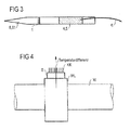
- FIG. 4 shows a side view of a device for monitoring a storage temperature.
- Temperature monitoring is required in many applications to monitor operability and, in the event of too high or too low a temperature, trigger a corresponding response to, for example, preventive equipment maintenance or wear history diagnostics. ⁇ . To enable.
- the device for monitoring the storage temperature, is mounted on a shaft W via a shaft bearing WL, in which a thermally fed transmitter S with at least one sensor 8 in the form of a temperature sensor is present.
- the temperature sensor may be mounted on or in the shaft bearing WL.
- the data transmission takes place via radio.
- the solution presented can be very compact, requires no connection cables and no maintenance. Since no wear parts (eg batteries) need to be serviced, the housing of the entire assembly can be hermetically sealed, which also increases the reliability. Finally, no cable laying is required during the installation, but it is only the plant control to announce that a new temperature monitoring point has been installed.
- the thermal transducer element 1 is a thermal transducer, in which preferably its one side is connected to the plant part to be monitored, while its other side is connected to a location which compares (eg in the case of an over-temperature of the plant part to be monitored) is cooler.
- This is typically a heat sink KK or the housing. Since the generated voltages are relatively small, the thermo-converter is conveniently composed of a series connection and / or a parallel connection of many thermoelectric generator elements.
- the logic module 4 monitors the measured value of the temperature sensor 81 for exceeding a (possibly preset) limit value TGRENZ. If TGRENZ is exceeded and / or undershot, then a transmission telegram is generated by the logic module 4 and sent via the data transmission unit 5, 6 to a system control, which is equipped with a corresponding radio receiver 9, 10 for this purpose. According to FIG. 2 the radio receiver 9, 10 a receiving antenna 9 and a high-frequency receiving stage 10. This transmission telegram can the temperature T at the measuring point, but also z. B. contain an identification code and / or additional information. Regardless of the course of the temperature T in the logic module 4 can optionally be permanently stored to z. B. for diagnostic purposes after a system failure available.
- a message when reaching or falling below the limit can be sent, or it may, for. B. the time since exceeding the limit in the transmission telegram may be included.
- the use of multiple limits is possible, for. Eg for early warning, alarm and system shutdown.
- the sensor 8 is an accumulating sensor in which a measured value integrating over time is detected by the energy transfer.
- a temperature profile in a nonvolatile memory can be recorded as a sensor 8, the memory is preferably in the form of an extremely low-energy EEPROM memory.
- analog storage methods such. For example: discharge of at least one capacitor or vaporization by the influence of temperature, the discharge of electrified materials by radioactive radiation (accumulated radiation exposure), electrochemical reactions such as hydrolysis, magnetic storage methods, etc. can be used for (usually integrating) storage of temperature influences and other measured variables.
- the entire temperature history or a part thereof or the accumulated measured value is sent by radio.
- the transmitter as a separate component or z. B. integrated into the logic board a monitoring unit, z. B. a threshold switch, which triggers the transmission process when exceeding a certain sufficient amount of energy.
Landscapes
- Physics & Mathematics (AREA)
- General Physics & Mathematics (AREA)
- Arrangements For Transmission Of Measured Signals (AREA)
- Measurement Of The Respiration, Hearing Ability, Form, And Blood Characteristics Of Living Organisms (AREA)
- Selective Calling Equipment (AREA)
- Measuring Temperature Or Quantity Of Heat (AREA)
Applications Claiming Priority (2)
| Application Number | Priority Date | Filing Date | Title |
|---|---|---|---|
| DE10125058.4A DE10125058B4 (de) | 2001-05-22 | 2001-05-22 | Thermisch speisbarer Sender und Sensorsystem |
| EP02747158.0A EP1389332B1 (fr) | 2001-05-22 | 2002-05-22 | Emetteur a alimentation thermique et systeme de detection |
Related Parent Applications (2)
| Application Number | Title | Priority Date | Filing Date |
|---|---|---|---|
| EP02747158.0A Division-Into EP1389332B1 (fr) | 2001-05-22 | 2002-05-22 | Emetteur a alimentation thermique et systeme de detection |
| EP02747158.0 Division | 2002-05-22 |
Publications (2)
| Publication Number | Publication Date |
|---|---|
| EP2261621A2 true EP2261621A2 (fr) | 2010-12-15 |
| EP2261621A3 EP2261621A3 (fr) | 2013-02-06 |
Family
ID=7685803
Family Applications (3)
| Application Number | Title | Priority Date | Filing Date |
|---|---|---|---|
| EP02747158.0A Expired - Lifetime EP1389332B1 (fr) | 2001-05-22 | 2002-05-22 | Emetteur a alimentation thermique et systeme de detection |
| EP10183408A Withdrawn EP2261622A3 (fr) | 2001-05-22 | 2002-05-22 | Emetteur à alimentation thermique et système de détection |
| EP10183404A Withdrawn EP2261621A3 (fr) | 2001-05-22 | 2002-05-22 | Emetteur à alimentation thermique et système de détection |
Family Applications Before (2)
| Application Number | Title | Priority Date | Filing Date |
|---|---|---|---|
| EP02747158.0A Expired - Lifetime EP1389332B1 (fr) | 2001-05-22 | 2002-05-22 | Emetteur a alimentation thermique et systeme de detection |
| EP10183408A Withdrawn EP2261622A3 (fr) | 2001-05-22 | 2002-05-22 | Emetteur à alimentation thermique et système de détection |
Country Status (4)
| Country | Link |
|---|---|
| US (2) | US7392022B2 (fr) |
| EP (3) | EP1389332B1 (fr) |
| DE (1) | DE10125058B4 (fr) |
| WO (1) | WO2002095707A1 (fr) |
Cited By (1)
| Publication number | Priority date | Publication date | Assignee | Title |
|---|---|---|---|---|
| DE102022131935A1 (de) * | 2022-12-02 | 2024-06-13 | Miele & Cie. Kg | Gargeschirr, Kochsystem, Verfahren zum Betreiben des Kochsystems und Sensoreinheit |
Families Citing this family (62)
| Publication number | Priority date | Publication date | Assignee | Title |
|---|---|---|---|---|
| DE10025561A1 (de) | 2000-05-24 | 2001-12-06 | Siemens Ag | Energieautarker Hochfrequenzsender |
| DE60235173D1 (de) | 2001-07-03 | 2010-03-11 | Face Internat Corp | Selbstversorgendes schalterinitialisierungssystem |
| DE10137504A1 (de) * | 2001-07-31 | 2003-02-27 | Enocean Gmbh | Thermisch antreibbare Spannungsversorgung |
| DE10150128C2 (de) | 2001-10-11 | 2003-10-02 | Enocean Gmbh | Drahtloses Sensorsystem |
| US7557433B2 (en) * | 2004-10-25 | 2009-07-07 | Mccain Joseph H | Microelectronic device with integrated energy source |
| US8455751B2 (en) | 2003-12-02 | 2013-06-04 | Battelle Memorial Institute | Thermoelectric devices and applications for the same |
| KR101157216B1 (ko) * | 2003-12-02 | 2012-07-03 | 바텔리 메모리얼 인스티튜트 | 열전 디바이스 및 그 응용 장치 |
| US20050139250A1 (en) * | 2003-12-02 | 2005-06-30 | Battelle Memorial Institute | Thermoelectric devices and applications for the same |
| US7851691B2 (en) | 2003-12-02 | 2010-12-14 | Battelle Memorial Institute | Thermoelectric devices and applications for the same |
| US7834263B2 (en) | 2003-12-02 | 2010-11-16 | Battelle Memorial Institute | Thermoelectric power source utilizing ambient energy harvesting for remote sensing and transmitting |
| RU2347921C2 (ru) * | 2004-03-02 | 2009-02-27 | Роузмаунт Инк. | Технологическое устройство с усовершенствованным обеспечением электропитанием |
| US8538560B2 (en) | 2004-04-29 | 2013-09-17 | Rosemount Inc. | Wireless power and communication unit for process field devices |
| US8145180B2 (en) | 2004-05-21 | 2012-03-27 | Rosemount Inc. | Power generation for process devices |
| US8160535B2 (en) | 2004-06-28 | 2012-04-17 | Rosemount Inc. | RF adapter for field device |
| US7262693B2 (en) | 2004-06-28 | 2007-08-28 | Rosemount Inc. | Process field device with radio frequency communication |
| DE102004050658A1 (de) * | 2004-10-18 | 2006-04-27 | Metrona Wärmemesser Union Gmbh | Vorrichtung zur Übertragung von Verbrauchsdaten mit Ultra-Wide-Band (UWB) |
| US9184364B2 (en) | 2005-03-02 | 2015-11-10 | Rosemount Inc. | Pipeline thermoelectric generator assembly |
| US20070215599A1 (en) * | 2006-03-17 | 2007-09-20 | W.C. Bradley Company | Systems and methods for predicting the time to change the temperature of an object |
| DE102006014444A1 (de) * | 2006-03-29 | 2007-10-04 | Abb Patent Gmbh | Einrichtung zur Energieversorgung von Feldgeräten |
| US7913566B2 (en) | 2006-05-23 | 2011-03-29 | Rosemount Inc. | Industrial process device utilizing magnetic induction |
| DE102006024167A1 (de) * | 2006-05-23 | 2007-11-29 | Enocean Gmbh | Thermogenerator |
| US20090025773A1 (en) * | 2006-05-31 | 2009-01-29 | Ingo Stark | Thermoelectric generator with micro-electrostatic energy converter |
| US7626114B2 (en) | 2006-06-16 | 2009-12-01 | Digital Angel Corporation | Thermoelectric power supply |
| US8188359B2 (en) | 2006-09-28 | 2012-05-29 | Rosemount Inc. | Thermoelectric generator assembly for field process devices |
| US20080136641A1 (en) * | 2006-12-06 | 2008-06-12 | Algotronix, Ltd. | Thermal Active Tag for Electronic Designs and Intellectual Property Cores |
| DE102007018245A1 (de) * | 2007-03-30 | 2008-10-02 | E.G.O. Elektro-Gerätebau GmbH | Temperatursonde für einen Ofen, Ofen und Verfahren zum Betrieb eines Ofens |
| DE102007019403B4 (de) * | 2007-04-23 | 2009-05-14 | Miele & Cie. Kg | Temperaturmesssonde, insbesondere für ein Haushaltsgerät |
| US20090084421A1 (en) * | 2007-09-28 | 2009-04-02 | Battelle Memorial Institute | Thermoelectric devices |
| KR20090062013A (ko) * | 2007-12-12 | 2009-06-17 | 삼성전자주식회사 | 보조 전력 공급 유닛, 상기 보조 전력 공급 유닛을 구비한전력 공급기, 상기 전력 공급기를 구비한 전자기기, 및상기 전력 공급기를 이용한 전자기기의 절전 작동 방법 |
| DE102008003793A1 (de) * | 2008-01-10 | 2009-07-16 | BSH Bosch und Siemens Hausgeräte GmbH | Sensor-Aktor-System |
| US8250924B2 (en) | 2008-04-22 | 2012-08-28 | Rosemount Inc. | Industrial process device utilizing piezoelectric transducer |
| US8929948B2 (en) | 2008-06-17 | 2015-01-06 | Rosemount Inc. | Wireless communication adapter for field devices |
| CN102084307B (zh) | 2008-06-17 | 2014-10-29 | 罗斯蒙特公司 | 用于具有低压本质安全钳的现场设备的rf适配器 |
| CN102067048B (zh) | 2008-06-17 | 2017-03-08 | 罗斯蒙特公司 | 用于具有可变压降的现场设备的rf适配器 |
| US8694060B2 (en) | 2008-06-17 | 2014-04-08 | Rosemount Inc. | Form factor and electromagnetic interference protection for process device wireless adapters |
| CA2726534C (fr) | 2008-06-17 | 2016-03-22 | Rosemount Inc. | Adaptateur rf pour dispositif de terrain a derivation de courant en boucle |
| CN101667738A (zh) * | 2008-09-01 | 2010-03-10 | 深圳富泰宏精密工业有限公司 | 充电装置及充电方法 |
| US7977924B2 (en) | 2008-11-03 | 2011-07-12 | Rosemount Inc. | Industrial process power scavenging device and method of deriving process device power from an industrial process |
| JP4752904B2 (ja) * | 2008-12-09 | 2011-08-17 | 日本電気株式会社 | 温度測定回路、及び、方法 |
| US8626087B2 (en) | 2009-06-16 | 2014-01-07 | Rosemount Inc. | Wire harness for field devices used in a hazardous locations |
| US9674976B2 (en) | 2009-06-16 | 2017-06-06 | Rosemount Inc. | Wireless process communication adapter with improved encapsulation |
| FR2959657B1 (fr) * | 2010-05-06 | 2012-06-22 | Commissariat Energie Atomique | Transducteur de variation temporelle de température, puce électronique incorporant ce transducteur et procédé de fabrication de cette puce |
| US20130201033A1 (en) * | 2010-08-09 | 2013-08-08 | Gabriel Cohn | Sensor systems wirelessly utilizing power infrastructures and associated systems and methods |
| US10761524B2 (en) | 2010-08-12 | 2020-09-01 | Rosemount Inc. | Wireless adapter with process diagnostics |
| US20130005372A1 (en) | 2011-06-29 | 2013-01-03 | Rosemount Inc. | Integral thermoelectric generator for wireless devices |
| US9310794B2 (en) | 2011-10-27 | 2016-04-12 | Rosemount Inc. | Power supply for industrial process field device |
| DE102012221410A1 (de) | 2012-11-23 | 2014-06-12 | Zf Friedrichshafen Ag | Kommunikationsvorrichtungen, Funkschalter und Verfahren zur Kommunikation |
| DE102013222163A1 (de) | 2013-10-31 | 2015-05-21 | Robert Bosch Gmbh | Elektrische Schaltung und Verfahren zur Herstellung einer elektrischen Schaltung |
| US9826338B2 (en) | 2014-11-18 | 2017-11-21 | Prophecy Sensorlytics Llc | IoT-enabled process control and predective maintenance using machine wearables |
| US10638295B2 (en) | 2015-01-17 | 2020-04-28 | Machinesense, Llc | System and method for turbomachinery preventive maintenance and root cause failure determination |
| US10648735B2 (en) | 2015-08-23 | 2020-05-12 | Machinesense, Llc | Machine learning based predictive maintenance of a dryer |
| US20160245279A1 (en) | 2015-02-23 | 2016-08-25 | Biplab Pal | Real time machine learning based predictive and preventive maintenance of vacuum pump |
| US10613046B2 (en) | 2015-02-23 | 2020-04-07 | Machinesense, Llc | Method for accurately measuring real-time dew-point value and total moisture content of a material |
| US20160245686A1 (en) | 2015-02-23 | 2016-08-25 | Biplab Pal | Fault detection in rotor driven equipment using rotational invariant transform of sub-sampled 3-axis vibrational data |
| US10599982B2 (en) | 2015-02-23 | 2020-03-24 | Machinesense, Llc | Internet of things based determination of machine reliability and automated maintainenace, repair and operation (MRO) logs |
| US20160313216A1 (en) | 2015-04-25 | 2016-10-27 | Prophecy Sensors, Llc | Fuel gauge visualization of iot based predictive maintenance system using multi-classification based machine learning |
| US10481195B2 (en) | 2015-12-02 | 2019-11-19 | Machinesense, Llc | Distributed IoT based sensor analytics for power line diagnosis |
| US9823289B2 (en) | 2015-06-01 | 2017-11-21 | Prophecy Sensorlytics Llc | Automated digital earth fault system |
| US10921792B2 (en) | 2017-12-21 | 2021-02-16 | Machinesense Llc | Edge cloud-based resin material drying system and method |
| DE102018110784A1 (de) * | 2018-05-04 | 2019-11-07 | Abb Schweiz Ag | Autonomes drahtloses Sensorgerät mit reduziertem Energieverbrauch |
| DE102020003879A1 (de) | 2020-06-29 | 2021-12-30 | Daimler Ag | Verbrennungskraftmaschine mit energiesparender Sensorik |
| US12092528B2 (en) * | 2021-06-22 | 2024-09-17 | Everactive, Inc. | Monitors for pressurized systems |
Citations (2)
| Publication number | Priority date | Publication date | Assignee | Title |
|---|---|---|---|---|
| DE3643236C2 (fr) | 1986-12-18 | 1990-02-08 | Ruhrkohle Ag, 4300 Essen, De | |
| WO1998036395A2 (fr) | 1997-02-12 | 1998-08-20 | Siemens Aktiengesellschaft | Dispositif et procede pour produire des signaux haute frequence codes |
Family Cites Families (20)
| Publication number | Priority date | Publication date | Assignee | Title |
|---|---|---|---|---|
| US4001798A (en) * | 1975-09-18 | 1977-01-04 | Rockwell International Corporation | Self-contained sensor |
| US4160234A (en) * | 1976-03-29 | 1979-07-03 | Gould Inc. | Abnormal tire condition sensing system |
| US4300119A (en) * | 1979-09-06 | 1981-11-10 | Facet Enterprises, Inc. | Power generator for telemetry transmitter |
| US4522512A (en) * | 1982-05-05 | 1985-06-11 | The United States Of America As Represented By The Secretary Of The Army | Thermal conductivity measurement method |
| US4647836A (en) | 1984-03-02 | 1987-03-03 | Olsen Randall B | Pyroelectric energy converter and method |
| US4629424A (en) * | 1984-08-30 | 1986-12-16 | Integrated Ionics, Inc. | Intraoral ambient sensing device |
| US4654573A (en) * | 1985-05-17 | 1987-03-31 | Flexible Manufacturing Systems, Inc. | Power transfer device |
| DE3703030A1 (de) | 1987-02-02 | 1988-09-08 | Siemens Ag | Testanordnung fuer hochgeschwindigkeits-ic |
| DE4424773A1 (de) | 1994-07-05 | 1996-01-11 | Paul Drude Inst Fuer Festkoerp | Fernmeßsystem |
| EP0778942B1 (fr) * | 1994-08-31 | 2002-02-27 | Honeywell Inc. | Controleur de structure a distance a alimentation autonome |
| WO1997032172A1 (fr) * | 1996-02-29 | 1997-09-04 | Shell Internationale Research Maatschappij B.V. | Procede pour diminuer la quantite de composants a bas points d'ebullition dans un gaz naturel liquefie |
| US5793309A (en) * | 1996-08-14 | 1998-08-11 | Lockheed Martin Corporation | Short range electromagnetic proximity detection |
| US6166625A (en) * | 1996-09-26 | 2000-12-26 | Donnelly Corporation | Pyroelectric intrusion detection in motor vehicles |
| DE19828170A1 (de) | 1998-06-24 | 1999-12-30 | Bsh Bosch Siemens Hausgeraete | Kochgeschirr für intelligente Herde |
| DE19933815A1 (de) | 1999-07-20 | 2001-01-25 | Abb Research Ltd | Verfahren und Anordnung zur drahtlosen Informationsübertragung, Anordnungen für einen Teilnehmer und eine Basisstation hierzu und Informationssystem für eine eine Vielzahl von Sensoren aufweisende Maschine |
| EP1275161B1 (fr) * | 2000-04-18 | 2007-03-07 | Pirelli Tyre S.p.A. | Generateur piezo-electrique pour detecteurs situes a l'interieur de pneus de vehicule |
| US6882128B1 (en) * | 2000-09-27 | 2005-04-19 | Science Applications International Corporation | Method and system for energy reclamation and reuse |
| US6570386B2 (en) * | 2001-07-30 | 2003-05-27 | Hewlett-Packard Development Company, L.P. | System and method for providing power to electrical devices |
| US6591610B2 (en) * | 2001-11-26 | 2003-07-15 | Sony Corporation | Converting dissipated heat to work energy using a thermo-acoustic generator |
| US7081693B2 (en) * | 2002-03-07 | 2006-07-25 | Microstrain, Inc. | Energy harvesting for wireless sensor operation and data transmission |
-
2001
- 2001-05-22 DE DE10125058.4A patent/DE10125058B4/de not_active Expired - Lifetime
-
2002
- 2002-05-22 US US10/478,084 patent/US7392022B2/en not_active Expired - Lifetime
- 2002-05-22 EP EP02747158.0A patent/EP1389332B1/fr not_active Expired - Lifetime
- 2002-05-22 EP EP10183408A patent/EP2261622A3/fr not_active Withdrawn
- 2002-05-22 WO PCT/DE2002/001848 patent/WO2002095707A1/fr not_active Ceased
- 2002-05-22 EP EP10183404A patent/EP2261621A3/fr not_active Withdrawn
-
2008
- 2008-05-14 US US12/152,349 patent/US8150340B2/en not_active Expired - Fee Related
Patent Citations (2)
| Publication number | Priority date | Publication date | Assignee | Title |
|---|---|---|---|---|
| DE3643236C2 (fr) | 1986-12-18 | 1990-02-08 | Ruhrkohle Ag, 4300 Essen, De | |
| WO1998036395A2 (fr) | 1997-02-12 | 1998-08-20 | Siemens Aktiengesellschaft | Dispositif et procede pour produire des signaux haute frequence codes |
Cited By (1)
| Publication number | Priority date | Publication date | Assignee | Title |
|---|---|---|---|---|
| DE102022131935A1 (de) * | 2022-12-02 | 2024-06-13 | Miele & Cie. Kg | Gargeschirr, Kochsystem, Verfahren zum Betreiben des Kochsystems und Sensoreinheit |
Also Published As
| Publication number | Publication date |
|---|---|
| WO2002095707A1 (fr) | 2002-11-28 |
| EP2261622A2 (fr) | 2010-12-15 |
| US20040242169A1 (en) | 2004-12-02 |
| EP1389332A1 (fr) | 2004-02-18 |
| EP2261621A3 (fr) | 2013-02-06 |
| DE10125058A1 (de) | 2002-12-12 |
| US8150340B2 (en) | 2012-04-03 |
| US7392022B2 (en) | 2008-06-24 |
| DE10125058B4 (de) | 2014-02-27 |
| EP1389332B1 (fr) | 2015-03-04 |
| US20080220727A1 (en) | 2008-09-11 |
| EP2261622A3 (fr) | 2013-02-06 |
Similar Documents
| Publication | Publication Date | Title |
|---|---|---|
| EP1389332B1 (fr) | Emetteur a alimentation thermique et systeme de detection | |
| EP1435079B1 (fr) | Système de détection sans fil | |
| DE4235187A1 (de) | Einrichtung zum Ablesen von Verbrauchswerten in einem Gebäude anfallender Verbrauchsmengen | |
| EP3416457A1 (fr) | Procédé de fonctionnement d'un système de cuisson inductif | |
| WO2001091315A2 (fr) | Emetteur haute frequence a autonomie energetique | |
| EP2072982B1 (fr) | Procédé de fonctionnement d'un appareil de mesure de consommation, notamment un répartiteur de coûts de chauffage | |
| DE102007037895A1 (de) | Modul mit einer Funksendeempfangseinrichtung und einem Aktor, System und Verfahren mit einem Modul und einer zentralen Einheit | |
| EP2568071B1 (fr) | Appareil ménager destiné à traiter une marchandise, système équipé de ce type d'appareil ménager et procédé destiné à commander un appareil ménager de ce type | |
| AT524412B1 (de) | Verfahren zur Datenübertragung von Verbrauchsmessgeräten | |
| DE19824471B4 (de) | Verfahren zur Übertragung von Daten | |
| DE19526635A1 (de) | Funkuhr für Hausgeräte | |
| DE102017005625B4 (de) | Verfahren zum Betrieb eines elektronischen Datenerfassungsgeräts und Datenerfassungsgerät | |
| EP3449215B1 (fr) | Procédé et dispositif de communication bidirectionnelle entre des appareils de mesure et des collecteurs de données | |
| EP3313149A2 (fr) | Procédé de communication | |
| DE102012015406A1 (de) | Verfahren und Vorrichtung zur Optimierung des RFID-Feldes einer Zugangskontrolleinrichtung | |
| EP2150084A2 (fr) | Procédé et dispositif de transmission de données | |
| EP2539984B1 (fr) | Dispositif et procédé d'intégration d'appareils électriques dans un système dans le cadre de la gestion de la demande | |
| EP0468304B1 (fr) | Dispositif de télécommande, particulièrement pour appareils de chauffage électriques domestiques | |
| DE102011008398B4 (de) | Energiesparende Datenübertragungstechnik | |
| DE10040905A1 (de) | Vorrichtung zur Steuerung von Sensoren und zur Verarbeitung und Übertrgung von Messwerten | |
| DE102014001856A1 (de) | Kühl- und/oder Gefriergerät | |
| EP3261260B1 (fr) | Appareil ménager électrique comprenant un dispositif de transmission de données et dispositif de réception de données provenant d'un tel dispositif | |
| CN109283908A (zh) | 一种智能家电控制系统 | |
| DE102005036250A1 (de) | Funkübertragungssystem | |
| DE102016105150A1 (de) | Vorrichtung zur Steuerung einer abgesetzten Benutzerschnittstelle |
Legal Events
| Date | Code | Title | Description |
|---|---|---|---|
| PUAI | Public reference made under article 153(3) epc to a published international application that has entered the european phase |
Free format text: ORIGINAL CODE: 0009012 |
|
| AC | Divisional application: reference to earlier application |
Ref document number: 1389332 Country of ref document: EP Kind code of ref document: P |
|
| AK | Designated contracting states |
Kind code of ref document: A2 Designated state(s): AT BE CH FR GB LI |
|
| PUAL | Search report despatched |
Free format text: ORIGINAL CODE: 0009013 |
|
| AK | Designated contracting states |
Kind code of ref document: A3 Designated state(s): AT BE CH FR GB LI |
|
| RIC1 | Information provided on ipc code assigned before grant |
Ipc: G01K 1/14 20060101ALI20130102BHEP Ipc: G01K 1/02 20060101AFI20130102BHEP |
|
| 17P | Request for examination filed |
Effective date: 20130806 |
|
| RBV | Designated contracting states (corrected) |
Designated state(s): AT BE CH FR GB LI |
|
| GRAP | Despatch of communication of intention to grant a patent |
Free format text: ORIGINAL CODE: EPIDOSNIGR1 |
|
| INTG | Intention to grant announced |
Effective date: 20140919 |
|
| STAA | Information on the status of an ep patent application or granted ep patent |
Free format text: STATUS: THE APPLICATION IS DEEMED TO BE WITHDRAWN |
|
| 18D | Application deemed to be withdrawn |
Effective date: 20141201 |