EP2263546B1 - Dispositif et procédé pour l'échantillonnage de tissus - Google Patents
Dispositif et procédé pour l'échantillonnage de tissus Download PDFInfo
- Publication number
- EP2263546B1 EP2263546B1 EP10181577A EP10181577A EP2263546B1 EP 2263546 B1 EP2263546 B1 EP 2263546B1 EP 10181577 A EP10181577 A EP 10181577A EP 10181577 A EP10181577 A EP 10181577A EP 2263546 B1 EP2263546 B1 EP 2263546B1
- Authority
- EP
- European Patent Office
- Prior art keywords
- body portion
- tubular body
- arms
- cutting element
- pair
- Prior art date
- Legal status (The legal status is an assumption and is not a legal conclusion. Google has not performed a legal analysis and makes no representation as to the accuracy of the status listed.)
- Expired - Lifetime
Links
- 238000005070 sampling Methods 0.000 title claims description 55
- 238000000034 method Methods 0.000 title description 7
- 239000000463 material Substances 0.000 claims description 39
- 239000012530 fluid Substances 0.000 claims description 6
- 238000006073 displacement reaction Methods 0.000 claims description 3
- 239000000523 sample Substances 0.000 description 15
- 210000004556 brain Anatomy 0.000 description 6
- 230000001953 sensory effect Effects 0.000 description 6
- 239000012620 biological material Substances 0.000 description 5
- 239000012472 biological sample Substances 0.000 description 5
- 210000001519 tissue Anatomy 0.000 description 5
- 241000283690 Bos taurus Species 0.000 description 4
- 230000000694 effects Effects 0.000 description 4
- 239000007787 solid Substances 0.000 description 4
- 208000024777 Prion disease Diseases 0.000 description 3
- 238000003745 diagnosis Methods 0.000 description 3
- -1 e.g. Substances 0.000 description 3
- 230000000007 visual effect Effects 0.000 description 3
- 208000020406 Creutzfeldt Jacob disease Diseases 0.000 description 2
- 208000003407 Creutzfeldt-Jakob Syndrome Diseases 0.000 description 2
- 208000010859 Creutzfeldt-Jakob disease Diseases 0.000 description 2
- 102000029797 Prion Human genes 0.000 description 2
- 108091000054 Prion Proteins 0.000 description 2
- 239000013060 biological fluid Substances 0.000 description 2
- 210000000133 brain stem Anatomy 0.000 description 2
- 230000000295 complement effect Effects 0.000 description 2
- 238000010276 construction Methods 0.000 description 2
- 238000011109 contamination Methods 0.000 description 2
- 201000010099 disease Diseases 0.000 description 2
- 208000037265 diseases, disorders, signs and symptoms Diseases 0.000 description 2
- 229920001903 high density polyethylene Polymers 0.000 description 2
- 239000004700 high-density polyethylene Substances 0.000 description 2
- 238000003780 insertion Methods 0.000 description 2
- 230000037431 insertion Effects 0.000 description 2
- 238000012986 modification Methods 0.000 description 2
- 230000004048 modification Effects 0.000 description 2
- 238000000465 moulding Methods 0.000 description 2
- 238000012360 testing method Methods 0.000 description 2
- 210000001186 vagus nerve Anatomy 0.000 description 2
- 241001465754 Metazoa Species 0.000 description 1
- 208000012902 Nervous system disease Diseases 0.000 description 1
- 208000025966 Neurological disease Diseases 0.000 description 1
- 241001494479 Pecora Species 0.000 description 1
- 239000004743 Polypropylene Substances 0.000 description 1
- 208000018756 Variant Creutzfeldt-Jakob disease Diseases 0.000 description 1
- 230000002159 abnormal effect Effects 0.000 description 1
- 238000009825 accumulation Methods 0.000 description 1
- 238000004458 analytical method Methods 0.000 description 1
- 210000003484 anatomy Anatomy 0.000 description 1
- 230000009286 beneficial effect Effects 0.000 description 1
- 239000008280 blood Substances 0.000 description 1
- 210000004369 blood Anatomy 0.000 description 1
- 208000005881 bovine spongiform encephalopathy Diseases 0.000 description 1
- 210000003169 central nervous system Anatomy 0.000 description 1
- 210000001175 cerebrospinal fluid Anatomy 0.000 description 1
- 238000012790 confirmation Methods 0.000 description 1
- 230000003247 decreasing effect Effects 0.000 description 1
- 230000003412 degenerative effect Effects 0.000 description 1
- 238000000605 extraction Methods 0.000 description 1
- 239000012634 fragment Substances 0.000 description 1
- 238000003018 immunoassay Methods 0.000 description 1
- 230000002452 interceptive effect Effects 0.000 description 1
- 206010023497 kuru Diseases 0.000 description 1
- 239000003550 marker Substances 0.000 description 1
- 210000000056 organ Anatomy 0.000 description 1
- 235000011837 pasties Nutrition 0.000 description 1
- 210000002381 plasma Anatomy 0.000 description 1
- 239000004033 plastic Substances 0.000 description 1
- 229920003023 plastic Polymers 0.000 description 1
- 229920001155 polypropylene Polymers 0.000 description 1
- 102000004169 proteins and genes Human genes 0.000 description 1
- 108090000623 proteins and genes Proteins 0.000 description 1
- 208000008864 scrapie Diseases 0.000 description 1
- 238000012216 screening Methods 0.000 description 1
- 230000035945 sensitivity Effects 0.000 description 1
- 210000002966 serum Anatomy 0.000 description 1
- 238000003307 slaughter Methods 0.000 description 1
- 239000012780 transparent material Substances 0.000 description 1
- 238000011282 treatment Methods 0.000 description 1
- 210000002700 urine Anatomy 0.000 description 1
Images



Classifications
-
- A—HUMAN NECESSITIES
- A61—MEDICAL OR VETERINARY SCIENCE; HYGIENE
- A61B—DIAGNOSIS; SURGERY; IDENTIFICATION
- A61B10/00—Instruments for taking body samples for diagnostic purposes; Other methods or instruments for diagnosis, e.g. for vaccination diagnosis, sex determination or ovulation-period determination; Throat striking implements
- A61B10/02—Instruments for taking cell samples or for biopsy
- A61B10/0233—Pointed or sharp biopsy instruments
- A61B10/0266—Pointed or sharp biopsy instruments means for severing sample
-
- A—HUMAN NECESSITIES
- A61—MEDICAL OR VETERINARY SCIENCE; HYGIENE
- A61B—DIAGNOSIS; SURGERY; IDENTIFICATION
- A61B10/00—Instruments for taking body samples for diagnostic purposes; Other methods or instruments for diagnosis, e.g. for vaccination diagnosis, sex determination or ovulation-period determination; Throat striking implements
- A61B10/02—Instruments for taking cell samples or for biopsy
- A61B10/0233—Pointed or sharp biopsy instruments
- A61B10/0283—Pointed or sharp biopsy instruments with vacuum aspiration, e.g. caused by retractable plunger or by connected syringe
-
- A—HUMAN NECESSITIES
- A61—MEDICAL OR VETERINARY SCIENCE; HYGIENE
- A61B—DIAGNOSIS; SURGERY; IDENTIFICATION
- A61B17/00—Surgical instruments, devices or methods
- A61B17/32—Surgical cutting instruments
- A61B17/3205—Excision instruments
- A61B17/32053—Punch like cutting instruments, e.g. using a cylindrical or oval knife
-
- A—HUMAN NECESSITIES
- A61—MEDICAL OR VETERINARY SCIENCE; HYGIENE
- A61B—DIAGNOSIS; SURGERY; IDENTIFICATION
- A61B90/00—Instruments, implements or accessories specially adapted for surgery or diagnosis and not covered by any of the groups A61B1/00 - A61B50/00, e.g. for luxation treatment or for protecting wound edges
- A61B90/06—Measuring instruments not otherwise provided for
- A61B2090/061—Measuring instruments not otherwise provided for for measuring dimensions, e.g. length
-
- A—HUMAN NECESSITIES
- A61—MEDICAL OR VETERINARY SCIENCE; HYGIENE
- A61B—DIAGNOSIS; SURGERY; IDENTIFICATION
- A61B90/00—Instruments, implements or accessories specially adapted for surgery or diagnosis and not covered by any of the groups A61B1/00 - A61B50/00, e.g. for luxation treatment or for protecting wound edges
- A61B90/06—Measuring instruments not otherwise provided for
- A61B2090/063—Measuring instruments not otherwise provided for for measuring volume
-
- A—HUMAN NECESSITIES
- A61—MEDICAL OR VETERINARY SCIENCE; HYGIENE
- A61B—DIAGNOSIS; SURGERY; IDENTIFICATION
- A61B90/00—Instruments, implements or accessories specially adapted for surgery or diagnosis and not covered by any of the groups A61B1/00 - A61B50/00, e.g. for luxation treatment or for protecting wound edges
- A61B90/39—Markers, e.g. radio-opaque or breast lesions markers
- A61B2090/3937—Visible markers
Definitions
- the present disclosure is directed to tissue sampling devices and, more particularly, to tissue sampling devices including sensory feedback elements.
- sampling devices e.g., pipettes, syringes, etc.
- sampling devices consist of a cylindrical barrel having a distal end adapted to permit passage of biological materials therethrough and a proximal end adapted to receive a stopper and plunger rod assembly.
- the stopper functions to provide a fluid tight seal between itself and the barrel so that movement of the stopper along the barrel will cause the biological material to be drawn into or forced out of the barrel through the distal end.
- the stopper is moved along the barrel by applying axial force to the plunger rod which is connected to the stopper.
- the plunger rod is sufficiently long to be accessible outside of the barrel.
- indicia such as volume measuring indicia, are provided along the length of the barrel to indicate to the user the volume of the biological material contained within the barrel.
- the material drawn into or forced out of the sampling device can consist of biological fluids, e.g., blood, plasma, serum, urine, cerebrospinal fluid, etc., or solids, e.g., organs, tissue fragments, etc., which are not distributed in a systematically homogeneous manner in the sampling device as compared to biological fluid.
- biological fluids e.g., blood, plasma, serum, urine, cerebrospinal fluid, etc.
- solids e.g., organs, tissue fragments, etc.
- TSE transmissible spongiform encephalopathies
- BSE bovine spongiform encephalopathy
- Soft biological sample is to be understood as meaning a sample of a biological material whose consistency is such that it can be cut effortlessly with a tool such as a scalpel, e.g., brain matter.
- Brain matter is to be understood as meaning any portion of the mass constituting the central nervous system, and particularly, but not exclusively, the anatomical part conventionally called the “brain stem”, especially that which is centered on the sensory and motor nuclei of the vagus nerve, whether said matter be in the natural state or whether it has been treated, e.g. obtained in the form of a pasty ground material.
- the present device includes feedback elements provided on the tubular body and/or the plunger assembly for providing a user of the sampling device with audible and/or tactile indications regarding an amount of displacement of the plunger assembly relative to the body portion.
- the stopper is adapted for fluid tight engagement with the body portion.
- the device further includes at least one cutting element associated with the distal end of the tubular body portion.
- the cutting element can include three arms extending radially inward from the inner surface of the body portion. The three arms can have free ends or be joined to one another at the longitudinal central axis of the body portion.
- the cutting element can be a pair of opposed arms extending radially inward from the inner surface of the body portion, and a third arm extending radially inward from the inner surface of the body portion.
- the pair of arms extend toward the central longitudinal axis of the body portion.
- the third arm extends beyond the central longitudinal axis of the body portion.
- the third arm is disposed at a substantially equi-distant location between the pair of opposed arms.
- each arm includes an unsupported free end.
- the cutting element includes a plurality of arms extending radially inward from an inner surface of the body portion.
- Each arm includes an unsupported free end.
- the free ends of each of the arms do not extend across the central longitudinal axis of the body portion.
- the cutting element includes at least a pair of arms extending inward from an inner surface of the body portion, wherein each arm includes a free end.
- the pair of arms of the cutting element are parallel to, and spaced apart from one another.
- the pair of arms of the cutting element may extend in opposite directions to one another.
- the pair of arms of the cutting element may extend in the same direction as one another.
- the pair of arms may be orthogonal to one another.
- FIG. 1 is a side elevational view, partially broken away, of a sampling device ;
- FIG. 2 is a cross-sectional side elevational view of the sampling device of FIG. 1 ;
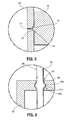
- FIG. 3 is an enlarged side view of the area indicated as 3 of FIG. 2 ;
- FIG. 4 is an enlarged side view of the area indicated as 4 of FIG. 2 ;
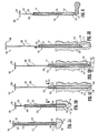
- FIGS. 5A to 5E illustrate an exemplary method of using the sampling device of FIGS. 1 to 4 for the collection of a biological sample
- FIG. 6 illustrates a method of extruding the biological sample from the sampling device of FIGS. 1 to 4 ;
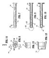
- FIG. 7 is a side elevational view of the body portion of the sampling device of FIGS. 1 to 4 ;
- FIG. 8 is an front elevational view of the body portion of FIG. 7 ;
- FIG. 9 is a longitudinal cross-sectional view of the body portion of FIG. 7 , as taken through 9 - 9 of FIG. 8 ;
- FIG. 10 is a longitudinal cross-sectional view of the body portion of FIG. 7 , as taken through 10 - 10 of FIG. 8 ;
- FIG. 11 is a cross-sectional view of the body portion of FIG. 7 , as taken through 11 - 11 of FIG. 8 ;
- FIG. 12 is an enlarged view of the body portion of the area indicated 12 of FIG. 9 ;
- FIG. 13 is an enlarged view of the body portion of the area indicated 13 of FIG. 9 ;
- FIG. 14 is a side elevational view of the plunger assembly of the sampling device of FIGS. 1 to 4 ;
- FIG. 15 is a top plan view of the plunger assembly of FIG. 14 ;
- FIG. 16 is a cross-sectional view of the plunger assembly of FIGS. 14 and 15 , as taken through 16 - 16 of FIG. 15 ;
- FIG. 17 is a cross-sectional view of the plunger assembly of FIGS. 14 and 15 , as taken through 17 - 17 of FIG. 15 ;
- FIG. 18 is a front end view of the plunger assembly of FIG. 14 ;
- FIG. 19 is an enlarged partial longitudinal cross-section view of a distally extending arcuate cutting element, positioned at the distal end of the body portion;
- FIG. 19A is an enlarged partial longitudinal cross-section view of a proximally extending arcuate cutting element , positioned at the distal end of the body portion;
- FIG. 20 is an enlarged side elevational view of the sampling device of FIG. 1 illustrating indicia formed on an outer surface thereof;
- FIG. 21 is a side elevational view of the body portion of a sampling device
- FIG. 22 is an front elevational view of the body portion of FIG. 21 ;
- FIG. 23 is a longitudinal cross-sectional view of the body portion of FIG. 21 , as taken through 23 - 23 of FIG. 22 ;
- FIG. 24 is a longitudinal cross-sectional view of the body portion of FIG. 21 , as taken through 24 - 24 of FIG. 22 ;
- FIG. 25 is a cross-sectional view of the body portion of FIG. 21 , as taken through 25 - 25 of FIG. 22 ;
- FIG. 26 is an enlarged view of the body portion of the area indicated 26 of FIG. 23 ;
- FIG. 27 is an enlarged view of the body portion of the area indicated 27 of FIG. 23 ;
- FIG. 28 is a longitudinal cross-sectional view of a sampling device
- FIG. 29 is a distal end view of the sampling device of FIG. 28 ;
- FIG. 30 is an enlarged view of the area indicated as 30 of the sampling device of FIG. 28 ;
- FIG. 31 is an enlarged view of the area indicated as 31 of the sampling device of FIG. 28 ;
- FIG. 32 is a longitudinal cross-sectional view of a distal end of a sampling device in accordance with an embodiment of the present disclosure
- FIG. 33 is a distal end view of the sampling device of FIG. 32 ;
- FIG. 34 is a cross-sectional view of the distal end of the sampling device of FIGS. 32 and 33 , as taken through 34-34 of FIG. 33 ;
- FIG. 35 is a longitudinal cross-sectional view of a distal end of a sampling device
- FIG. 36 is a distal end view of the sampling device of FIG. 35 ;
- FIG. 37 is a distal end view of a sampling device illustrating a cutting element according to an alternate embodiment of the present disclosure
- FIG. 38 is a transverse cross-sectional view of the sampling device of FIGS. 28-31 as taken through 38-38 of FIG. 28 ;
- FIG. 39 is a distal end view of a sampling device illustrating a cutting element according to another alternate embodiment of the present disclosure.
- FIG. 40 is a distal end view of a sampling device illustrating a cutting element according to still another alternate embodiment of the present disclosure.
- FIG. 41 is a distal end view of a sampling device illustrating a cutting element according to yet another alternate embodiment of the present disclosure.
- sampling devices are generally designated as 100.
- the presently disclosed sampling devices 100 will be described and illustrated hereinafter in connection with specific embodiments and uses, such as, for example, use in the medical field, it will be readily appreciated and understood by one skilled in the art that the presently disclosed sampling device 100 may be adapted for usage in other applications and fields of use as well.
- proximal as is traditional, will refer to the end of the device which is closest to the operator while the term “distal” will refer to the end of the device which is furthest away from the operator.
- sampling device 100 includes a hollow cylindrical or tubular body portion 102 defining a chamber 104 therein and having a longitudinal axis "X".
- body portion 102 is fabricated from a clear or transparent material such as a polypropylene and the like.
- Body portion 102 includes a proximal end 106 having an opening 107 and a distal end 108 having an opening 109.
- Distal end 108 is adapted to form a slicing edge 110 by gradually decreasing, in a distal direction, the thickness of the wall of body portion 102.
- distal end 108 can have a generally frusto-conical shape over its outer periphery, over its inner periphery or over both its outer and inner periphery.
- body portion 102 can have a blunt end.
- Chamber 104 of body portion 102 preferably has a volume which is equal to at least 300 ⁇ l.
- Body portion 102 is provided with volume measuring indicia in the form of metrical markings 112, along substantially the entire length thereof, for use in determining the volume of material within chamber 104 of sampling device 100 and, in turn, the volume of material to be expunged from chamber 104 of sampling device 100.
- Indicia or markings 112 can be etched into body portion 102, printed on the outer or inner surface of body portion 102, or otherwise provided on the outer or inner surface of body portion 102. It is within the purview of the present disclosure to include some or all of these various means for providing volume measuring indicia on body portion 102.
- Indicia or markings 112 are preferably provided, at least at, 100 ⁇ l intervals from one another.
- each marking 112 marks-off 100 ⁇ l of volume of chamber 104 of body portion 102. While indicia or markings 112 are preferably provided at 100 ⁇ l from one another, it is envisioned and within the scope of the present disclosure for indicia or markings 112 to be spaced at any desired and/or operatively beneficial interval from one another.
- Sampling device 100 further includes a plunger assembly 120 slidably positionable within chamber 104 of body portion 102.
- Plunger assembly 120 includes a movable piston rod 122 including a proximal end portion 122a extending from opening 107 of proximal end 106 of body portion 102 and a distal end portion 122b extending into chamber 104 of body portion 102.
- Piston rod 122 may be made of suitable material such as, for example, high density polyethylene (HDPE).
- Plunger assembly 120 further includes a stopper 124 operatively connected to distal end portion 122b of piston rod 122.
- Stopper 124 is slidably positioned within body portion 102, in fluid tight engagement therewith, and is capable of moving material from chamber 104, through opening 109 of distal end 108 of body portion 102, upon its distal axial movement relative to opening 109. Moreover, stopper 124 is capable of drawing material into chamber 104, through opening 109 of distal end 108 of body portion 102, upon placement of distal end 108 into fluid material and upon proximal axial movement of stopper 124 relative to opening 109 of distal end 108 of body portion 102. It is envisioned that stopper 124 may be fabricated from rubber or the like.
- a cutting element 130 such as a cutting wire or integrally molded part, can be provided across distal end 108 of body portion 102.
- cutting element 130 can extend diametrically across distal end 108 of body portion 102 (i.e. straight across and attached at each end).
- Cutting element 130 can be of circular, triangular or other cross-sectional profile. In general, any cross-sectional profile which is capable of giving element 130 a cutting effect when it is displaced relative to a sample of soft biological material is suitable.
- a cutting element may take the form of an arcuate, a "U-shaped", or a “C-shaped” cutting element 130a which extends distally beyond distal end 108 of body portion 102.
- An example of such an arcuate cutting element is disclosed in WO 99/23950 .
- arcuate cutting element 130a may extend proximally into body portion 102. In this configuration, there is the added advantage that the user may wipe distal end 108 clean without interfering with arcuate cutting element 130a.
- Other cutting element configurations are disclosed, supra.
- Construction of arcuate cutting element 130a may be achieved by molding the entire arcuate cutting element as one unitary member or separately molding the multiple elements making up the arcuate cutting element and attaching the multiple elements to distal end 108 of body portion 102.
- Sampling device 100 is provided with one or more sensory feedback elements 140, e.g., audible, tactile, etc., which provide the user with sensory indications as to the position of plunger assembly 120, in particular stopper 124, relative to body portion 102.
- Sensory feedback elements 140 can be provided, for example, at 100 ⁇ l, 200 ⁇ l or 300 ⁇ l increments along the length of body portion 102, preferably at 500 ⁇ l.
- current tests typically require approximately 300 ⁇ l +/- 10% to be dispensed from the device.
- feedback elements 140 include a nub or projection 142, preferably an annular nub or projection, extending radially outward from the surface of stopper 124 and an annular groove 144 formed in the inner surface of body portion 102.
- projection 142 and annular grooves 144 have complementary cross-sectional profiles (e.g., rounded, pointed, squared and the like). In this manner, as stopper 124 is displaced through body portion 102, projection 142 engages and disengages grooves 144.
- the engagement and disengagement of projection 142 with grooves 144 creates at least one of an audile sound (e.g., a click) and a vibration or other tactile effect due to the temporary interruption of the smooth passage of stopper 124 through body portion 102 and along the inner surface of chamber 104.
- an audile sound e.g., a click
- a vibration or other tactile effect due to the temporary interruption of the smooth passage of stopper 124 through body portion 102 and along the inner surface of chamber 104.
- grooves (or protrusions) 144 are positioned along the length of body portion 102 such that stopper 124 and/or projections 142 engage grooves 144 at 300 ⁇ l intervals or at 150 ⁇ l. Accordingly, as the user displaces plunger assembly 120 in a distal or proximal direction, feedback elements 140 enable the user to readily ascertain the quantity of material drawn into chamber 104 or expunged from chamber 104 without having to make a visual observation and/or confirmation regarding the same.
- feedback elements 140 enable the user to draw in or expunge the desired and/or necessary amount of material into/from chamber 104 of body portion 102.
- tissue sampling devices requiring visual observation of the quantity of their contents, were generally filled completely to ensure enough material was drawn into the chamber and/or needed to be reintroduced into the site to draw in additional material if not enough material was drawn into the chamber during the first insertion.
- feedback elements 140 can include an annular projection 142 extending from stopper 124 and annular grooves 144 formed in the inner surface of body portion 102, it is envisioned that feedback elements 140 can include a series of projections, preferably bumps or annular projections, extending radially inward from the inner surface of body portion 102 at predetermined locations (not shown).
- stopper 124 can have an annular groove formed on the outer surface thereof or merely interact with the projections as a surface (such as the proximal or distal end portion) of the stopper passes by the projection(s).
- feedback elements 140 can include a series of grooves 144 formed along the inner surface of body portion 102.
- stopper 124 inter-engages grooves 144 and creates an effect which can be tactilely sensed.
- the inner surface of body portion 102 preferably includes one or more grooves 144 or protrusions (not shown) formed therein that interact with stopper 124 of plunger assembly 120 to provide tactile feedback to the user as stopper 124 traverses body portion 102.
- four grooves 144 1-4 are formed at predetermined locations along the inner surface of body portion 102. Fewer or more grooves 144 may be provided as desired.
- Grooves 144 may be formed to extend at least partially, preferably completely, around the entire inner circumference of body portion 102 at the predetermined locations. By varying the depth of grooves 144 or the height of the protrusions and the degree to which such groove 144 or protrusion is present (i.e., partially or completely around the inner circumference of body portion 102), the degree of resistance to movement experienced by stopper 124 of plunger assembly 120 may be varied. Grooves 144 and protrusions may be formed adjacent one another to achieve the desired tactile resistance (e.g., as seen in FIG. 24 , a stopping element 146, extending from the inner surface of body portion 102, may be formed adjacent proximal-most groove 144 4 ).
- proximal-most tactile indicator or feedback element be of greater resistance than the other tactile indicators or feedback elements. This would allow the user to withdraw piston assembly 120 to a point corresponding to the proximal-most position and, through tactile feedback, understand that plunger assembly 120 is at this position due to resistance that is greater than other tactile indicator locations. Determination of the proximal-most position of plunger assembly 120 is useful so that the user knows the starting point of plunger assembly 120 (without having to look at the device) before plunger assembly 120 is moved in the distal direction (i.e., to expel tissue and/or fluids contained in body portion 102). Tactile indication of a proximal location of plunger assembly 120 also indicates that further proximal movement of plunger assembly 120 may cause plunger assembly 120 to be completely withdrawn from body portion 102.
- sampling device 100 can include feedback elements 140a including a series of nubs or projections 142a, preferably an annular nub or projection, extending radially outward from the surface of and along the length of piston rod 122 of plunger assembly 120 and an annular groove 144a formed along the inner periphery of opening 107 of proximal end 106 of body portion 102.
- Projections 142a are preferably spaced a fixed distance from one another, e.g., a distance equal to the equivalent of about 100 ⁇ l or about 150 ⁇ l of material in chamber 104 of body portion 102.
- projections 142a and annular groove 144a have complementary cross-sectional profiles (e.g., rounded, pointed, squared and the like). In this manner, as plunger assembly 120 is displaced through body portion 102, projections 142a engage and disengage groove 144. The engagement and disengagement of projections 142 with groove 144a creates at least one of an audile sound (e.g., a click) and/or a vibration or other tactile effect due to the temporary interruption of the smooth passage of piston rod 122 through opening 107 of proximal end 106 of body portion 102.
- an audile sound e.g., a click
- a vibration or other tactile effect due to the temporary interruption of the smooth passage of piston rod 122 through opening 107 of proximal end 106 of body portion 102.
- feedback elements 140a include an annular projections 142a extending from piston rod 122 and an annular groove 144a formed in the periphery of opening 107 of proximal end 106 of body portion 102
- feedback elements 140a can include annular grooves formed in the outer surface of piston rod 122 and a projection, preferably an annular projection, extending radially inward from the periphery of opening 107 of proximal end 106 of body portion 102 (not shown).
- FIGS. 5A to 5E a method of collecting a sample of material with sampling device 100 will be shown and described.
- distal end 102 of sampling device 100 is placed in contact with material to be collected "M".
- stopper 124 is positioned in close proximity to opening 109 of distal end 108 of body portion 102.
- body portion 102 of sampling device 100 is driven into material "M", in the direction of arrow "A".
- material "M” enters chamber 104 through opening 109 of distal end 108 and thereby displaces plunger assembly 120 in a direction opposite the direction of body portion 102, i.e., opposite to direction "A".
- body portion 102 is driven into material "M” until the desired and/or necessary quantity of material “M” is “drawn” into chamber 104 of body portion 102.
- driving plunger assembly 120 in a direction opposite to the relative direction of movement of body portion 102, feedback elements 140, 140a provide the user with an indication as to the quantity of material "M” contained in chamber 104. For example, one “click” would indicate that approximately 100 ⁇ l or 150 ⁇ l of material "M” was “drawn” into chamber 104, and that each "click” would indicate that an additional 100 ⁇ l and/or 150 ⁇ l was “drawn” into chamber 104.
- sampling device 100 As seen in FIG. 5D , with the desired amount of material "M” within chamber 104, sampling device 100, at least body portion 102, is rotated, as indicated by arrow "B", an amount sufficient for cutting element 130 to free the sample of material "S” contained in chamber 104 from the remainder of material "M". With sample “S” free from material “M”, sampling device 100 is withdrawn from material "M” while maintaining the position of plunger assembly 120 relative to body portion 102.
- plunger assembly 120 In order to expel, sample “S” from chamber 104 of body portion 102, plunger assembly 120 is displaced in a distal direction, e.g., in the direction of arrow "A", relative to body portion 102. As plunger assembly 120 is driven in a distal direction, stopper 124 forces sample “S” out opening 107 of distal end 108 of body portion 102.
- feedback elements 140 or 140a provide the user with audible and/or tactile indication and/or feedback as to the position of plunger assembly 120 relative to body portion 102 and, more particularly, the quantity of sample "S" expelled from chamber 104 of body portion 102.
- each inter-engagement of annular projection 142 with annular groove 144 represents approximately and, more preferably, exactly 300 ⁇ l of sample "S" being expelled from chamber 104 of body portion 102.
- chamber 104 preferably has a volume of at least about 300 ⁇ l, it is envisioned that chamber 104 can have any practical volume. In a preferred embodiment, chamber 104 has a volume from at least about 600 ⁇ l to about 1000 ⁇ l.
- inter-engagement of projection 142 with annular grooves 144 is described as occurring at each 100 ⁇ l, 150 ⁇ l, 200 ⁇ l or 300 ⁇ l increments, it is envisioned that such inter-engagement can occur at any volumetric increment.
- plunger assembly 120 can be provided with a handle 126 secured to proximal end 122a of piston rod 122 for facilitating the displacement of plunger assembly 120 relative to body portion 102.
- indicia e.g., a company logo, etc.
- indicia may be provided on the outer surface of body portion 102 by not frosting the areas where the indicia is to appear or by frosting the areas where the indicia is to appear by a different degree as compared to the remainder of body portion 102.
- sampling devices 200 will be shown and described. Sampling devices 200 are similar to sampling device 100 and will only be discussed in detail to the extent necessary to identify differences in construction and operation. In FIGS. 28-38 , the elements of sampling device 200, corresponding elements from sampling device 100 of FIGS. 1-27 , will be identified with corresponding reference characters.
- Sampling device 200 includes a hollow cylindrical or tubular body portion 202 defining a chamber 204 therein.
- Body portion 202 includes a proximal end 206 having an opening 207 and a distal end 208 having an opening 209.
- Distal end 208 is adapted to form a slicing edge 210.
- Body portion 202 is further provided with metrical markings 212 for use in determining the volume of material within chamber 204 and, in turn, the volume of material to be expunged from chamber 204.
- Sampling device 200 further includes a plunger assembly 220 slidably positionable within chamber 204 of body portion 202.
- Plunger assembly 220 includes a piston rod 222 including a proximal end portion 222a extending from proximal end 206 of body portion 202 and a distal end portion 222b extending into chamber 204 of body portion 202.
- Plunger assembly 220 further includes a stopper 224 operatively connected to distal end portion 222b of piston rod 222.
- piston rod 222 has a generally cruciform transverse cross-sectional profile defining four (4) longitudinally extending walls 226a. While four (4) walls are shown and described, it is envisioned and within the scope of the present disclosure that any number of walls 226a may be provided, including and not limited to three, five, six, etc, or that rod 222 may be circular, rectangular or other cross-sectional shapes.
- Each wall 226a is provided with a series of projections 226b formed along an outer edge thereof.
- Each projection 226b includes a dimple or depression 226c formed in an apex thereof.
- walls 226a and projections 226b are sized such that projections 226b are in close proximity with an inner surface of body portion 202.
- the projections 226b and dimples 226c form a part of a feedback element 244.
- annular race, recess or ring 250 is preferably formed in the inner surface of and at or near slicing edge 210 of body portion 202.
- Annular race 250 is dimensioned to receive annular projection 242 extending around stopper 224.
- Annular projection 242 is substantially similar to projection 142 of stopper 124 (see FIG. 17 ).
- Annular recess 250 allows for the distal end of stopper 242 to be in a less compressed position during shipping and storage.
- feedback element 244 further includes an annular rib 243 formed along the inner surface of chamber 204 of body portion 202.
- annular rib 243 is formed at, near, or some distance in from (distally of) opening 207 of proximal end 206 of body portion 202.
- dimples 226c of projections 226b of piston rod 222 inter-engage with annular rib 243 of body portion 202 to provide the user with tactile and/or audible feedback.
- dimples 226c and projection 226b are formed at locations along piston rod 222 corresponding to 150 ⁇ l of volume of chamber 204 of body portion 202.
- a cutting element 230a may be provided at distal end 208 of body portion 202.
- Cutting element 230a extends across distal end 208 of body portion 202.
- cutting element 230a is arcuate and extends proximally into body portion 202.
- cutting element 230a can extend directly across (diametrically across) body portion 202.
- a cutting element 230b in accordance with the present disclosure, may be provided at distal end 208 of body portion 202.
- Cutting element 230b includes a pair of arms/fingers 231a, 231b extending radially inward and angled into body portion 202.
- arms 231a, 231b terminate at a distance spaced from a central longitudinal axis of body portion 202.
- Cutting element 230b further includes a third arm/finger 231c extending radially inward from body portion 202 in a manner such that a distal end of third arm 231c extends between the pair of opposed arms 231a, 231b and beyond the central longitudinal axis of body portion 202.
- cutting element 230b has been shown with three arms 231a-231c, it is envisioned and within the scope of the present disclosure that cutting element 230b may be provided with only third arm 231c extending radially inward from body portion 202 and terminating at a location beyond the central longitudinal axis of body portion 202.
- a cutting element 230c may be provided at distal end 208 of body portion 202.
- Cutting element 230c includes a plurality of radially converging arms/fingers 233a-233c extending radially inward and at an angle into body portion 202 in such a manner that the distal ends of arms 233a-233c are joined to one another.
- arms 233a-233c are joined at a location axially aligned with the central longitudinal axis of body portion 202. While three arms 233a-233c are shown it is envisioned, that any number of arms may be provided.
- arms 233a-233c are spaced an equal radial distance from one another (e.g., 120°), however, it is envisioned that arms 233a-233c may be spaced any radial distance from one another.
- cutting elements 230a, 230b and 230c completely separate the sample "S", contained in chamber 204 of body portion 202, from the remainder of material "M".
- cutting element 230d may be provided with a plurality of radially inward converging arms/fingers 235a-235e extending from body portion 202.
- the distal ends of arms 235a-235e do not contact and/or are not joined with one another, and none of the distal ends of arms 235a-235e extend across the central longitudinal axis of body portion 202.
- the portion of sample “S” of material "M” located along the central longitudinal axis of body portion 202, is not directly separated from the remainder of material "M” by arms 235s-235e.
- cutting element 230 may include a pair of laterally spaced apart parallel arms extending inward from substantially opposite sides of body portion 202 ( FIG. 39 ); a pair of arms extending inward from body portion 202 and at an angle, preferably orthogonal, to one another ( FIG. 40 ); and a pair of laterally spaced apart parallel arms extending inward from substantially a common side of body portion 202 ( FIG. 41 ).
- Each arm of cutting elements 230 shown in FIGS. 39-41 include a free end which is not connected to body portion.
Landscapes
- Health & Medical Sciences (AREA)
- Life Sciences & Earth Sciences (AREA)
- Medical Informatics (AREA)
- Engineering & Computer Science (AREA)
- Biomedical Technology (AREA)
- Heart & Thoracic Surgery (AREA)
- Pathology (AREA)
- Molecular Biology (AREA)
- Surgery (AREA)
- Animal Behavior & Ethology (AREA)
- General Health & Medical Sciences (AREA)
- Public Health (AREA)
- Veterinary Medicine (AREA)
- Sampling And Sample Adjustment (AREA)
- Apparatus Associated With Microorganisms And Enzymes (AREA)
Claims (9)
- Dispositif pour obtenir un échantillon de l'intérieur d'un corps, comprenant :une partie formant corps tubulaire (102, 202) définissant une chambre (104, 204) destinée à recevoir un échantillon de matière en son sein, la partie formant corps tubulaire comportant une extrémité distale (108, 208), une extrémité proximale (106, 206) et définissant un axe central longitudinal ;un ensemble formant piston plongeur (120, 220) associé en fonctionnement à la partie formant corps tubulaire (102, 202), l'ensemble formant piston plongeur (120, 220) comportant un obturateur (124, 224) disposé en glissement au sein de la chambre (104, 204) de la partie formant corps tubulaire (102, 202), l'obturateur (124, 224) étant conçu pour un engagement étanche aux fluides avec la partie formant corps tubulaire (102, 202) ;des éléments de retour d'information (140, 140a, 244) situés sur au moins l'un des éléments parmi la partie formant corps tubulaire (102, 202) et l'ensemble formant piston plongeur (120, 220), destinés à donner, à un utilisateur du dispositif d'échantillonnage, au moins une indication parmi des indications sonores et tactiles ayant trait à la quantité de déplacement de l'ensemble formant piston plongeur (120, 220) par rapport à la partie formant corps tubulaire et au moins un élément de coupe (130, 130a, 230a, 230b, 230d), caractérisé en ce que l'au moins un élément de coupe comporte une pluralité de bras (231a-231c, 235a-235e) s'étendant radialement vers l'intérieur depuis l'extrémité distale ouverte (108, 208) de la partie formant corps tubulaire (102, 202), et angulaires dans la partie formant corps tubulaire (102, 202), chacun des bras comportant une extrémité libre non supportée disposée au sein de la partie formant corps tubulaire (102, 202).
- Dispositif selon l'une quelconque des revendications précédentes, dans lequel l'extrémité distale (108, 208) de la partie formant corps tubulaire (102, 202) définit un bord de coupe distale (110, 210).
- Dispositif selon l'une quelconque des revendications précédentes, dans lequel l'au moins un élément de coupe (130, 230b) comprend :une paire de bras opposés (213a, 231b) s'étendant radialement vers l'intérieur depuis la surface interne de la partie formant corps tubulaire (102, 202), la paire de bras (213a, 231b) s'étendant vers l'axe central longitudinal de la partie formant corps tubulaire (102, 202) ; etun troisième bras (231c) s'étendant radialement vers l'intérieur depuis la surface interne de la partie formant corps tubulaire (102, 202), le troisième bras (231c) s'étendant au-delà de l'axe central longitudinal de la partie formant corps tubulaire (102, 202), le troisième bras (231c) étant situé en un emplacement sensiblement équidistant entre les deux bras opposés formant paire (231a, 231b), chaque bras (213a, 231b, 231c) comprenant une extrémité libre non supportée.
- Dispositif selon l'une quelconque des revendications précédentes, dans lequel l'élément de coupe (130, 230b, 230d) comprend au moins une paire de bras (231a-231c, 235a-235e) s'étendant vers l'intérieur depuis la surface interne de la partie formant corps tubulaire (102, 202), chaque bras (231a-231c, 235a-235e) comprenant une extrémité libre.
- Dispositif selon l'une quelconque des revendications précédentes, dans lequel au moins deux bras en paire (231a, 231b) de l'élément de coupe (230b) sont parallèles l'un à l'autre.
- Dispositif selon l'une quelconque des revendications précédentes, dans lequel au moins deux bras en paire (231a, 231b) de l'élément de coupe (230b) sont espacés l'un de l'autre.
- Dispositif selon l'une quelconque des revendications précédentes, dans lequel au moins deux bras en paire (231a, 231b) de l'élément de coupe (230b) s'étendent dans des directions opposées l'un par rapport à l'autre.
- Dispositif selon l'une quelconque des revendications précédentes, dans lequel au moins deux bras en paire de l'élément de coupe s'étendent dans la même direction l'un que l'autre.
- Dispositif selon l'une quelconque des revendications précédentes, dans lequel au moins deux bras en paire sont perpendiculaires l'un à l'autre.
Applications Claiming Priority (6)
| Application Number | Priority Date | Filing Date | Title |
|---|---|---|---|
| US53047203P | 2003-12-16 | 2003-12-16 | |
| US54759904P | 2004-02-25 | 2004-02-25 | |
| US54874904P | 2004-02-27 | 2004-02-27 | |
| US54867104P | 2004-02-27 | 2004-02-27 | |
| US56589904P | 2004-04-26 | 2004-04-26 | |
| EP04814267.3A EP1699363B1 (fr) | 2003-12-16 | 2004-12-15 | Dispositif pour l'echantillonnage de tissus |
Related Parent Applications (2)
| Application Number | Title | Priority Date | Filing Date |
|---|---|---|---|
| EP04814267.3 Division | 2004-12-15 | ||
| EP04814267.3A Division-Into EP1699363B1 (fr) | 2003-12-16 | 2004-12-15 | Dispositif pour l'echantillonnage de tissus |
Publications (2)
| Publication Number | Publication Date |
|---|---|
| EP2263546A1 EP2263546A1 (fr) | 2010-12-22 |
| EP2263546B1 true EP2263546B1 (fr) | 2012-11-21 |
Family
ID=34705386
Family Applications (2)
| Application Number | Title | Priority Date | Filing Date |
|---|---|---|---|
| EP04814267.3A Expired - Lifetime EP1699363B1 (fr) | 2003-12-16 | 2004-12-15 | Dispositif pour l'echantillonnage de tissus |
| EP10181577A Expired - Lifetime EP2263546B1 (fr) | 2003-12-16 | 2004-12-15 | Dispositif et procédé pour l'échantillonnage de tissus |
Family Applications Before (1)
| Application Number | Title | Priority Date | Filing Date |
|---|---|---|---|
| EP04814267.3A Expired - Lifetime EP1699363B1 (fr) | 2003-12-16 | 2004-12-15 | Dispositif pour l'echantillonnage de tissus |
Country Status (6)
| Country | Link |
|---|---|
| US (1) | US7794410B2 (fr) |
| EP (2) | EP1699363B1 (fr) |
| JP (1) | JP4653115B2 (fr) |
| AU (1) | AU2004299086B2 (fr) |
| CA (1) | CA2549297C (fr) |
| WO (1) | WO2005058169A2 (fr) |
Families Citing this family (38)
| Publication number | Priority date | Publication date | Assignee | Title |
|---|---|---|---|---|
| US20080281226A1 (en) * | 2004-05-11 | 2008-11-13 | Inrad, Inc. | Core Biopsy Device with Specimen Length Adjustment |
| EP3097865B1 (fr) | 2005-02-07 | 2020-01-08 | Ivy Sports Medicine, LLC. | Système de fixation de suture intégralement interne pour la fixation d'un implant et réparation de tissu mou |
| US20230329700A1 (en) * | 2005-02-07 | 2023-10-19 | Stryker Corporation | System And Method For All-Inside Suture Fixation For Implant Attachment And Soft Tissue Repair |
| US8128640B2 (en) * | 2005-02-07 | 2012-03-06 | Ivy Sports Medicine LLC | System and method for all-inside suture fixation for implant attachment and soft tissue repair |
| US20070244513A1 (en) * | 2006-04-14 | 2007-10-18 | Ethicon Endo-Surgery, Inc. | Endoscopic device |
| CA2650013A1 (fr) * | 2006-04-21 | 2007-11-01 | Clevex, Inc. | Emporte-piece pour biopsie |
| DE102007002855A1 (de) * | 2006-06-06 | 2007-12-13 | Wolfram Schnepp-Pesch | Probenahmevorrichtung, insbesondere Biopsienadel |
| US8066717B2 (en) | 2007-03-19 | 2011-11-29 | Restoration Robotics, Inc. | Device and method for harvesting and implanting follicular units |
| JP5139007B2 (ja) * | 2007-08-22 | 2013-02-06 | オリンパス株式会社 | 観察用穴開け具 |
| WO2009117324A1 (fr) | 2008-03-18 | 2009-09-24 | Restoration Robotics, Inc. | Outils d’élimination d’unité biologique avec élément de retenue mobile |
| US20100082042A1 (en) * | 2008-09-30 | 2010-04-01 | Drews Michael J | Biological unit removal tool with occluding member |
| EP2298393A1 (fr) | 2009-09-16 | 2011-03-23 | Hamad Mohammed Alomar | Seringue et procédé de distribution d'un liquide de manière contrôlable |
| DE102010010967A1 (de) * | 2010-03-10 | 2011-09-15 | Slg Pharma Gmbh & Co. Kg | Vorfüllspritze |
| US8298246B2 (en) | 2010-04-01 | 2012-10-30 | Restoration Robotics, Inc. | Follicular unit removal tool with pivoting retention member |
| JP2012010758A (ja) * | 2010-06-29 | 2012-01-19 | Japan Medical Materials Corp | 穿孔ドリル及び穿孔ドリルシステム |
| JP2012130554A (ja) * | 2010-12-22 | 2012-07-12 | Ohkura Pharmaceutical Co Ltd | 供給装置 |
| EP2720616B1 (fr) | 2011-06-14 | 2021-02-24 | Frost Diagnostika GmbH | Dispositif pour le prélèvement et le traitement d'un échantillon |
| US9352312B2 (en) | 2011-09-23 | 2016-05-31 | Alere Switzerland Gmbh | System and apparatus for reactions |
| EP2838435B1 (fr) | 2012-04-16 | 2020-03-25 | Hathaway, Jeff M. | Dispositif de biopsie |
| CA2920835A1 (fr) | 2013-08-20 | 2015-02-26 | Anutra Medical, Inc. | Systeme de remplissage de seringue et procede associe |
| USD750768S1 (en) | 2014-06-06 | 2016-03-01 | Anutra Medical, Inc. | Fluid administration syringe |
| USD763433S1 (en) | 2014-06-06 | 2016-08-09 | Anutra Medical, Inc. | Delivery system cassette |
| USD774182S1 (en) | 2014-06-06 | 2016-12-13 | Anutra Medical, Inc. | Anesthetic delivery device |
| JP6392006B2 (ja) * | 2014-06-26 | 2018-09-19 | 株式会社貝印刃物開発センター | 皮膚切除具 |
| DE102015000999A1 (de) | 2015-01-27 | 2016-07-28 | Sarl Omsi | Kolben für Spritzen und Spritzen |
| US10660320B2 (en) * | 2015-04-21 | 2020-05-26 | Steven Bailey | Method and apparatus for injecting bait into fishing lures |
| CN104997552B (zh) * | 2015-04-27 | 2019-01-04 | 苏州同心医疗器械有限公司 | 一种外科开孔刀及其使用方法 |
| US10076352B2 (en) | 2015-05-29 | 2018-09-18 | Restoration Robotics, Inc. | Implantation needle |
| US10932769B2 (en) | 2016-05-26 | 2021-03-02 | Ivy Sports Medicine, Llc | System and method for all-inside suture fixation for implant attachment and soft tissue repair |
| CN109561914B (zh) * | 2016-08-30 | 2021-12-28 | 捷锐士股份有限公司 | 医疗装置柄部锁 |
| CA3050587A1 (fr) * | 2018-08-09 | 2020-02-09 | Adrian Pona | Appareil de biopsie a l`emporte-piece |
| CN112842404B (zh) * | 2020-12-24 | 2022-11-01 | 杭州市第三人民医院 | 一种泌尿科用穿刺针 |
| CN113318334A (zh) * | 2021-04-28 | 2021-08-31 | 蔡雅青 | 一种妇产科科室的给药器 |
| US11523834B1 (en) | 2022-06-20 | 2022-12-13 | University Of Utah Research Foundation | Cartilage and bone harvest and delivery system and methods |
| US11660194B1 (en) | 2022-06-20 | 2023-05-30 | University Of Utah Research Foundation | Cartilage and bone harvest and delivery system and methods |
| US12023047B1 (en) | 2023-07-14 | 2024-07-02 | University Of Utah Research Foundation | Cannulated trephine |
| US12196646B1 (en) * | 2024-08-02 | 2025-01-14 | King Saud University | Microorganism sampling tool |
| US12605169B1 (en) | 2025-06-06 | 2026-04-21 | University Of Utah Research Foundation | Osteochondral transfer systems and methods |
Family Cites Families (54)
| Publication number | Priority date | Publication date | Assignee | Title |
|---|---|---|---|---|
| US241864A (en) * | 1881-05-24 | hun-er | ||
| US1191831A (en) * | 1915-10-28 | 1916-07-18 | David W Royer | Bananaette-machine. |
| US2764981A (en) | 1955-09-01 | 1956-10-02 | Norman D Helmer | Multiple dosage syringe |
| DK112893B (da) * | 1966-07-25 | 1969-01-27 | Bay Schmith N | Blandingssprøjte til brug ved blanding af forud fastsatte mængder af væsker og faste stoffer. |
| US3577979A (en) * | 1968-02-06 | 1971-05-11 | Harry Van Der Gaast | Disposable surgical skin punch |
| US3938505A (en) * | 1974-08-16 | 1976-02-17 | Khosrow Jamshidi | Soft tissue biopsy aspirating device |
| US3990446A (en) * | 1975-02-18 | 1976-11-09 | Jewel Dean Randolph Taylor | Hypodermic syringe for stabilized aspiration by one hand |
| IT1069354B (it) * | 1976-03-05 | 1985-03-25 | Zanasi Nigris Spa | Perfezionamenti nei dosatori volume trici |
| US4142517A (en) * | 1976-07-23 | 1979-03-06 | Contreras Guerrero De Stavropo | Apparatus for extracting bone marrow specimens |
| US4649918A (en) * | 1980-09-03 | 1987-03-17 | Custom Medical Devices, Inc. | Bone core removing tool |
| US4346708A (en) * | 1981-04-20 | 1982-08-31 | Leveen Harry H | Syringe |
| US4549612A (en) * | 1983-12-27 | 1985-10-29 | Theresa Caldwell | Soil sampler |
| FR2585233A1 (fr) | 1985-07-26 | 1987-01-30 | Orlovic Radmila | Appareil chirurgical pour effectuer des biopsies et ses differentes applications |
| US4735905A (en) * | 1986-08-15 | 1988-04-05 | V-Tech, Inc. | Specimen-gathering apparatus and method |
| DE3843610A1 (de) * | 1988-01-13 | 1989-07-27 | Stephan Dr Diekmann | Trenn- oder reaktionssaeuleneinheit |
| US4873991A (en) * | 1988-09-21 | 1989-10-17 | Skinner Bruce A J | Biopsy needle |
| US4919146A (en) * | 1988-10-25 | 1990-04-24 | Medrad, Inc. | Biopsy device |
| US4956297A (en) | 1989-02-13 | 1990-09-11 | Minnesota Mining And Manufacturing Company | Device for obtaining predetermined amounts of bacteria |
| US5380492A (en) * | 1990-12-18 | 1995-01-10 | Seymour; Eugene H. | Sampling device and sample adequacy system |
| US5133360A (en) * | 1991-03-07 | 1992-07-28 | Spears Colin P | Spears retriever |
| US5324300A (en) * | 1991-10-25 | 1994-06-28 | Elias Elias G | Device for the controlled excision of tissue from a living body |
| US5462062A (en) * | 1991-12-13 | 1995-10-31 | Rubinstein; Daniel B. | Bone marrow biopsy needle with cutting and/or retaining device at distal end |
| JP2547520B2 (ja) * | 1992-01-21 | 1996-10-23 | ヴァリーラブ・インコーポレーテッド | トロカールのための電気外科的制御器 |
| US5357974A (en) * | 1993-03-04 | 1994-10-25 | Thomas F. Robinson | Bone marrow biopsy instrument |
| US5375608A (en) * | 1993-04-21 | 1994-12-27 | Tiefenbrun; Jonathan | Method and instrument assembly for use in obtaining biopsy |
| US5304124A (en) * | 1993-06-07 | 1994-04-19 | Essig Mitchell N | Myoma removal technique |
| US5573008A (en) * | 1993-10-29 | 1996-11-12 | Boston Scientific Corporation | Multiple biopsy sampling coring device |
| DE9414070U1 (de) | 1994-08-31 | 1994-11-10 | Fa. H. Hauptner, 42651 Solingen | Vorrichtung für die Verwendung im Schlachtbetrieb bei Bestimmungsverfahren für den Ebergeruchsstoff (Androstenon) im Fettgewebe von Schweineschlachtkörpern |
| US5786228A (en) | 1995-06-07 | 1998-07-28 | Biex, Inc. | Fluid collection kit and method |
| US5786227A (en) * | 1995-06-07 | 1998-07-28 | Biex, Inc. | Fluid collection kit and method |
| US5857982A (en) * | 1995-09-08 | 1999-01-12 | United States Surgical Corporation | Apparatus and method for removing tissue |
| US5582595A (en) * | 1995-09-28 | 1996-12-10 | Habley Medical Technology Corporation | Aspirating syringe having a plunger guide for a reciprocating plunger assembly |
| JP3236775B2 (ja) * | 1996-03-18 | 2001-12-10 | 株式会社オートネットワーク技術研究所 | コネクタの結合構造 |
| WO1997036160A1 (fr) | 1996-03-25 | 1997-10-02 | Vinther Torben Pilgaard | Appareil de prelevement et d'ejection d'echantillons de sol et utilisation |
| US5833628A (en) * | 1996-04-24 | 1998-11-10 | Yuan; Hansen | Graduated bone graft harvester |
| US5810806A (en) * | 1996-08-29 | 1998-09-22 | Ethicon Endo-Surgery | Methods and devices for collection of soft tissue |
| AU6325698A (en) | 1997-11-12 | 1999-05-31 | Stereotaxis, Inc. | Method and apparatus for obtaining tissue samples |
| US5961458A (en) * | 1997-11-18 | 1999-10-05 | Carewise Medical Products Corporation | Minimally invasive surgical probe for tissue identification and retrieval and method of use |
| US5925834A (en) * | 1997-12-16 | 1999-07-20 | Waters Investments Limited | Autosampler syringe with compression sealing |
| US6096010A (en) * | 1998-02-20 | 2000-08-01 | Becton, Dickinson And Company | Repeat-dose medication delivery pen |
| US6395011B1 (en) * | 1998-07-17 | 2002-05-28 | Johnson & Johnson | Method and apparatus for harvesting and implanting bone plugs |
| US6176326B1 (en) * | 1998-10-06 | 2001-01-23 | Soilcore, Inc. | Soil sampling measuring device |
| US6299842B1 (en) * | 1999-03-05 | 2001-10-09 | Meridian Bioscience, Inc. | Biological sampling and storage container utilizing a desiccant |
| DE19912322A1 (de) * | 1999-03-19 | 2000-09-28 | Vetter & Co Apotheker | Spritze für medizinische Zwecke |
| US7018365B2 (en) * | 1999-05-21 | 2006-03-28 | Micro Therapeutics, Inc. | Threaded syringe with quick stop |
| US6168576B1 (en) * | 1999-05-24 | 2001-01-02 | Irene N. Reynolds | Device for dispensing vaginal medication |
| US6162187A (en) * | 1999-08-02 | 2000-12-19 | Ethicon Endo-Surgery, Inc. | Fluid collection apparatus for a surgical device |
| US6579269B1 (en) * | 1999-09-21 | 2003-06-17 | Gennady I. Kleyman | Dosage device |
| SE9904539D0 (sv) * | 1999-12-10 | 1999-12-10 | Alphahelix Ab | Method and device for the handling of samples and reagents |
| FR2802640B1 (fr) | 1999-12-17 | 2003-01-03 | Pasteur Sanofi Diagnostics | Dispositif et procede de prelevement d'echantillon biologique |
| CA2345911C (fr) * | 2001-05-02 | 2009-02-17 | Joel S. Harris | Dispositif d'echantillonnage pour la collecte de materiau |
| US6793660B2 (en) * | 2001-08-20 | 2004-09-21 | Synthes (U.S.A.) | Threaded syringe for delivery of a bone substitute material |
| US7141036B2 (en) * | 2002-06-04 | 2006-11-28 | Syringe, Llc | Methods of applying a medicinal substance |
| US6972006B2 (en) * | 2002-09-18 | 2005-12-06 | G6 Science Corp. | Syringe device with resistive ridges and methods of use |
-
2004
- 2004-12-15 US US11/012,395 patent/US7794410B2/en active Active
- 2004-12-15 CA CA2549297A patent/CA2549297C/fr not_active Expired - Lifetime
- 2004-12-15 AU AU2004299086A patent/AU2004299086B2/en not_active Ceased
- 2004-12-15 EP EP04814267.3A patent/EP1699363B1/fr not_active Expired - Lifetime
- 2004-12-15 JP JP2006545365A patent/JP4653115B2/ja not_active Expired - Fee Related
- 2004-12-15 EP EP10181577A patent/EP2263546B1/fr not_active Expired - Lifetime
- 2004-12-15 WO PCT/US2004/042061 patent/WO2005058169A2/fr not_active Ceased
Also Published As
| Publication number | Publication date |
|---|---|
| WO2005058169A3 (fr) | 2005-10-27 |
| US7794410B2 (en) | 2010-09-14 |
| EP1699363A2 (fr) | 2006-09-13 |
| US20050131313A1 (en) | 2005-06-16 |
| JP4653115B2 (ja) | 2011-03-16 |
| JP2007513734A (ja) | 2007-05-31 |
| EP1699363B1 (fr) | 2014-03-12 |
| EP2263546A1 (fr) | 2010-12-22 |
| AU2004299086A1 (en) | 2005-06-30 |
| AU2004299086A2 (en) | 2005-06-30 |
| CA2549297A1 (fr) | 2005-06-30 |
| WO2005058169A2 (fr) | 2005-06-30 |
| AU2004299086B2 (en) | 2011-03-03 |
| CA2549297C (fr) | 2012-11-27 |
Similar Documents
| Publication | Publication Date | Title |
|---|---|---|
| EP2263546B1 (fr) | Dispositif et procédé pour l'échantillonnage de tissus | |
| AU779328B2 (en) | Device and method for taking a biological sample | |
| EP2156807B1 (fr) | Dispositif d'administration de marqueurs de biopsie | |
| US9717483B2 (en) | Access chamber and markers for biopsy device | |
| KR102013300B1 (ko) | 생검 장소 표시부 도포기 | |
| US20180116645A1 (en) | Stylet and Needle Combinations Used to Collect Tissue Samples During Endoscopic Procedures | |
| CN107847193A (zh) | 生物流体收集装置 | |
| EP1618847A2 (fr) | Dispositif d'homogénéisation de tissu | |
| EP3076877B1 (fr) | Dispositif de pénétration d'os amovible et procédés | |
| US20240099729A1 (en) | Bone marrow aspirate harvesting | |
| HK1191207B (en) | Biopsy marker delivery device | |
| HK1197798B (en) | Access chamber and markers for biopsy device | |
| HK1198802B (en) | Access chamber and markers for biopsy device |
Legal Events
| Date | Code | Title | Description |
|---|---|---|---|
| PUAI | Public reference made under article 153(3) epc to a published international application that has entered the european phase |
Free format text: ORIGINAL CODE: 0009012 |
|
| AC | Divisional application: reference to earlier application |
Ref document number: 1699363 Country of ref document: EP Kind code of ref document: P |
|
| AK | Designated contracting states |
Kind code of ref document: A1 Designated state(s): AT BE BG CH CY CZ DE DK EE ES FI FR GB GR HU IE IS IT LI LT LU MC NL PL PT RO SE SI SK TR |
|
| 17P | Request for examination filed |
Effective date: 20110622 |
|
| GRAJ | Information related to disapproval of communication of intention to grant by the applicant or resumption of examination proceedings by the epo deleted |
Free format text: ORIGINAL CODE: EPIDOSDIGR1 |
|
| GRAP | Despatch of communication of intention to grant a patent |
Free format text: ORIGINAL CODE: EPIDOSNIGR1 |
|
| GRAS | Grant fee paid |
Free format text: ORIGINAL CODE: EPIDOSNIGR3 |
|
| GRAA | (expected) grant |
Free format text: ORIGINAL CODE: 0009210 |
|
| AC | Divisional application: reference to earlier application |
Ref document number: 1699363 Country of ref document: EP Kind code of ref document: P |
|
| AK | Designated contracting states |
Kind code of ref document: B1 Designated state(s): AT BE BG CH CY CZ DE DK EE ES FI FR GB GR HU IE IS IT LI LT LU MC NL PL PT RO SE SI SK TR |
|
| REG | Reference to a national code |
Ref country code: GB Ref legal event code: FG4D |
|
| REG | Reference to a national code |
Ref country code: CH Ref legal event code: EP |
|
| REG | Reference to a national code |
Ref country code: AT Ref legal event code: REF Ref document number: 584627 Country of ref document: AT Kind code of ref document: T Effective date: 20121215 |
|
| REG | Reference to a national code |
Ref country code: IE Ref legal event code: FG4D |
|
| REG | Reference to a national code |
Ref country code: DE Ref legal event code: R096 Ref document number: 602004040176 Country of ref document: DE Effective date: 20130117 |
|
| REG | Reference to a national code |
Ref country code: NL Ref legal event code: VDEP Effective date: 20121121 |
|
| REG | Reference to a national code |
Ref country code: AT Ref legal event code: MK05 Ref document number: 584627 Country of ref document: AT Kind code of ref document: T Effective date: 20121121 |
|
| REG | Reference to a national code |
Ref country code: LT Ref legal event code: MG4D |
|
| PG25 | Lapsed in a contracting state [announced via postgrant information from national office to epo] |
Ref country code: FI Free format text: LAPSE BECAUSE OF FAILURE TO SUBMIT A TRANSLATION OF THE DESCRIPTION OR TO PAY THE FEE WITHIN THE PRESCRIBED TIME-LIMIT Effective date: 20121121 Ref country code: ES Free format text: LAPSE BECAUSE OF FAILURE TO SUBMIT A TRANSLATION OF THE DESCRIPTION OR TO PAY THE FEE WITHIN THE PRESCRIBED TIME-LIMIT Effective date: 20130304 Ref country code: SE Free format text: LAPSE BECAUSE OF FAILURE TO SUBMIT A TRANSLATION OF THE DESCRIPTION OR TO PAY THE FEE WITHIN THE PRESCRIBED TIME-LIMIT Effective date: 20121121 Ref country code: LT Free format text: LAPSE BECAUSE OF FAILURE TO SUBMIT A TRANSLATION OF THE DESCRIPTION OR TO PAY THE FEE WITHIN THE PRESCRIBED TIME-LIMIT Effective date: 20121121 |
|
| PG25 | Lapsed in a contracting state [announced via postgrant information from national office to epo] |
Ref country code: SI Free format text: LAPSE BECAUSE OF FAILURE TO SUBMIT A TRANSLATION OF THE DESCRIPTION OR TO PAY THE FEE WITHIN THE PRESCRIBED TIME-LIMIT Effective date: 20121121 Ref country code: GR Free format text: LAPSE BECAUSE OF FAILURE TO SUBMIT A TRANSLATION OF THE DESCRIPTION OR TO PAY THE FEE WITHIN THE PRESCRIBED TIME-LIMIT Effective date: 20130222 Ref country code: PL Free format text: LAPSE BECAUSE OF FAILURE TO SUBMIT A TRANSLATION OF THE DESCRIPTION OR TO PAY THE FEE WITHIN THE PRESCRIBED TIME-LIMIT Effective date: 20121121 Ref country code: BE Free format text: LAPSE BECAUSE OF FAILURE TO SUBMIT A TRANSLATION OF THE DESCRIPTION OR TO PAY THE FEE WITHIN THE PRESCRIBED TIME-LIMIT Effective date: 20121121 Ref country code: PT Free format text: LAPSE BECAUSE OF FAILURE TO SUBMIT A TRANSLATION OF THE DESCRIPTION OR TO PAY THE FEE WITHIN THE PRESCRIBED TIME-LIMIT Effective date: 20130321 |
|
| PG25 | Lapsed in a contracting state [announced via postgrant information from national office to epo] |
Ref country code: AT Free format text: LAPSE BECAUSE OF FAILURE TO SUBMIT A TRANSLATION OF THE DESCRIPTION OR TO PAY THE FEE WITHIN THE PRESCRIBED TIME-LIMIT Effective date: 20121121 |
|
| PG25 | Lapsed in a contracting state [announced via postgrant information from national office to epo] |
Ref country code: DK Free format text: LAPSE BECAUSE OF FAILURE TO SUBMIT A TRANSLATION OF THE DESCRIPTION OR TO PAY THE FEE WITHIN THE PRESCRIBED TIME-LIMIT Effective date: 20121121 Ref country code: SK Free format text: LAPSE BECAUSE OF FAILURE TO SUBMIT A TRANSLATION OF THE DESCRIPTION OR TO PAY THE FEE WITHIN THE PRESCRIBED TIME-LIMIT Effective date: 20121121 Ref country code: EE Free format text: LAPSE BECAUSE OF FAILURE TO SUBMIT A TRANSLATION OF THE DESCRIPTION OR TO PAY THE FEE WITHIN THE PRESCRIBED TIME-LIMIT Effective date: 20121121 Ref country code: BG Free format text: LAPSE BECAUSE OF FAILURE TO SUBMIT A TRANSLATION OF THE DESCRIPTION OR TO PAY THE FEE WITHIN THE PRESCRIBED TIME-LIMIT Effective date: 20130221 Ref country code: CZ Free format text: LAPSE BECAUSE OF FAILURE TO SUBMIT A TRANSLATION OF THE DESCRIPTION OR TO PAY THE FEE WITHIN THE PRESCRIBED TIME-LIMIT Effective date: 20121121 Ref country code: MC Free format text: LAPSE BECAUSE OF NON-PAYMENT OF DUE FEES Effective date: 20121231 |
|
| REG | Reference to a national code |
Ref country code: CH Ref legal event code: PL |
|
| PG25 | Lapsed in a contracting state [announced via postgrant information from national office to epo] |
Ref country code: NL Free format text: LAPSE BECAUSE OF FAILURE TO SUBMIT A TRANSLATION OF THE DESCRIPTION OR TO PAY THE FEE WITHIN THE PRESCRIBED TIME-LIMIT Effective date: 20121121 Ref country code: RO Free format text: LAPSE BECAUSE OF FAILURE TO SUBMIT A TRANSLATION OF THE DESCRIPTION OR TO PAY THE FEE WITHIN THE PRESCRIBED TIME-LIMIT Effective date: 20121121 Ref country code: IT Free format text: LAPSE BECAUSE OF FAILURE TO SUBMIT A TRANSLATION OF THE DESCRIPTION OR TO PAY THE FEE WITHIN THE PRESCRIBED TIME-LIMIT Effective date: 20121121 |
|
| REG | Reference to a national code |
Ref country code: IE Ref legal event code: MM4A |
|
| PLBE | No opposition filed within time limit |
Free format text: ORIGINAL CODE: 0009261 |
|
| STAA | Information on the status of an ep patent application or granted ep patent |
Free format text: STATUS: NO OPPOSITION FILED WITHIN TIME LIMIT |
|
| 26N | No opposition filed |
Effective date: 20130822 |
|
| PG25 | Lapsed in a contracting state [announced via postgrant information from national office to epo] |
Ref country code: CH Free format text: LAPSE BECAUSE OF NON-PAYMENT OF DUE FEES Effective date: 20121231 Ref country code: IE Free format text: LAPSE BECAUSE OF NON-PAYMENT OF DUE FEES Effective date: 20121215 Ref country code: LI Free format text: LAPSE BECAUSE OF NON-PAYMENT OF DUE FEES Effective date: 20121231 |
|
| REG | Reference to a national code |
Ref country code: DE Ref legal event code: R097 Ref document number: 602004040176 Country of ref document: DE Effective date: 20130822 |
|
| PG25 | Lapsed in a contracting state [announced via postgrant information from national office to epo] |
Ref country code: TR Free format text: LAPSE BECAUSE OF FAILURE TO SUBMIT A TRANSLATION OF THE DESCRIPTION OR TO PAY THE FEE WITHIN THE PRESCRIBED TIME-LIMIT Effective date: 20121121 |
|
| PG25 | Lapsed in a contracting state [announced via postgrant information from national office to epo] |
Ref country code: LU Free format text: LAPSE BECAUSE OF NON-PAYMENT OF DUE FEES Effective date: 20121215 Ref country code: CY Free format text: LAPSE BECAUSE OF FAILURE TO SUBMIT A TRANSLATION OF THE DESCRIPTION OR TO PAY THE FEE WITHIN THE PRESCRIBED TIME-LIMIT Effective date: 20121121 |
|
| PG25 | Lapsed in a contracting state [announced via postgrant information from national office to epo] |
Ref country code: HU Free format text: LAPSE BECAUSE OF FAILURE TO SUBMIT A TRANSLATION OF THE DESCRIPTION OR TO PAY THE FEE WITHIN THE PRESCRIBED TIME-LIMIT Effective date: 20041215 |
|
| REG | Reference to a national code |
Ref country code: FR Ref legal event code: PLFP Year of fee payment: 12 |
|
| PG25 | Lapsed in a contracting state [announced via postgrant information from national office to epo] |
Ref country code: IS Free format text: LAPSE BECAUSE OF FAILURE TO SUBMIT A TRANSLATION OF THE DESCRIPTION OR TO PAY THE FEE WITHIN THE PRESCRIBED TIME-LIMIT Effective date: 20121121 |
|
| REG | Reference to a national code |
Ref country code: FR Ref legal event code: PLFP Year of fee payment: 13 |
|
| REG | Reference to a national code |
Ref country code: FR Ref legal event code: PLFP Year of fee payment: 14 |
|
| PGFP | Annual fee paid to national office [announced via postgrant information from national office to epo] |
Ref country code: DE Payment date: 20211227 Year of fee payment: 18 Ref country code: FR Payment date: 20211227 Year of fee payment: 18 Ref country code: GB Payment date: 20211227 Year of fee payment: 18 |
|
| P01 | Opt-out of the competence of the unified patent court (upc) registered |
Effective date: 20230522 |
|
| REG | Reference to a national code |
Ref country code: DE Ref legal event code: R119 Ref document number: 602004040176 Country of ref document: DE |
|
| GBPC | Gb: european patent ceased through non-payment of renewal fee |
Effective date: 20221215 |
|
| PG25 | Lapsed in a contracting state [announced via postgrant information from national office to epo] |
Ref country code: GB Free format text: LAPSE BECAUSE OF NON-PAYMENT OF DUE FEES Effective date: 20221215 Ref country code: DE Free format text: LAPSE BECAUSE OF NON-PAYMENT OF DUE FEES Effective date: 20230701 |
|
| PG25 | Lapsed in a contracting state [announced via postgrant information from national office to epo] |
Ref country code: FR Free format text: LAPSE BECAUSE OF NON-PAYMENT OF DUE FEES Effective date: 20221231 |