EP2264249A2 - Tige de machine d'excavation - Google Patents
Tige de machine d'excavation Download PDFInfo
- Publication number
- EP2264249A2 EP2264249A2 EP10005755A EP10005755A EP2264249A2 EP 2264249 A2 EP2264249 A2 EP 2264249A2 EP 10005755 A EP10005755 A EP 10005755A EP 10005755 A EP10005755 A EP 10005755A EP 2264249 A2 EP2264249 A2 EP 2264249A2
- Authority
- EP
- European Patent Office
- Prior art keywords
- excavator
- excavator handle
- recesses
- box profile
- handle according
- Prior art date
- Legal status (The legal status is an assumption and is not a legal conclusion. Google has not performed a legal analysis and makes no representation as to the accuracy of the status listed.)
- Withdrawn
Links
- 238000010168 coupling process Methods 0.000 claims description 17
- 238000005859 coupling reaction Methods 0.000 claims description 17
- 230000008878 coupling Effects 0.000 claims description 16
- 230000003247 decreasing effect Effects 0.000 claims description 3
- 239000000835 fiber Substances 0.000 claims description 3
- 230000007935 neutral effect Effects 0.000 claims description 3
- 241000283153 Cetacea Species 0.000 claims description 2
- 238000010276 construction Methods 0.000 description 11
- 230000007797 corrosion Effects 0.000 description 4
- 238000005260 corrosion Methods 0.000 description 4
- 238000005336 cracking Methods 0.000 description 2
- 239000012857 radioactive material Substances 0.000 description 2
- 239000000565 sealant Substances 0.000 description 2
- 238000007789 sealing Methods 0.000 description 2
- 229910000831 Steel Inorganic materials 0.000 description 1
- 150000001875 compounds Chemical class 0.000 description 1
- 238000001514 detection method Methods 0.000 description 1
- 230000005611 electricity Effects 0.000 description 1
- 239000006260 foam Substances 0.000 description 1
- 238000005187 foaming Methods 0.000 description 1
- 239000003292 glue Substances 0.000 description 1
- 238000009434 installation Methods 0.000 description 1
- 239000002184 metal Substances 0.000 description 1
- 239000003973 paint Substances 0.000 description 1
- 239000010959 steel Substances 0.000 description 1
- XLYOFNOQVPJJNP-UHFFFAOYSA-N water Substances O XLYOFNOQVPJJNP-UHFFFAOYSA-N 0.000 description 1
- 238000003466 welding Methods 0.000 description 1
Images



Classifications
-
- E—FIXED CONSTRUCTIONS
- E02—HYDRAULIC ENGINEERING; FOUNDATIONS; SOIL SHIFTING
- E02F—DREDGING; SOIL-SHIFTING
- E02F3/00—Dredgers; Soil-shifting machines
- E02F3/04—Dredgers; Soil-shifting machines mechanically-driven
- E02F3/28—Dredgers; Soil-shifting machines mechanically-driven with digging tools mounted on a dipper- or bucket-arm, i.e. there is either one arm or a pair of arms, e.g. dippers, buckets
- E02F3/36—Component parts
- E02F3/38—Cantilever beams, i.e. booms;, e.g. manufacturing processes, forms, geometry or materials used for booms; Dipper-arms, e.g. manufacturing processes, forms, geometry or materials used for dipper-arms; Bucket-arms
-
- E—FIXED CONSTRUCTIONS
- E02—HYDRAULIC ENGINEERING; FOUNDATIONS; SOIL SHIFTING
- E02F—DREDGING; SOIL-SHIFTING
- E02F9/00—Component parts of dredgers or soil-shifting machines, not restricted to one of the kinds covered by groups E02F3/00 - E02F7/00
- E02F9/20—Drives; Control devices
- E02F9/22—Hydraulic or pneumatic drives
- E02F9/2264—Arrangements or adaptations of elements for hydraulic drives
- E02F9/2275—Hoses and supports therefor and protection therefor
Definitions
- the present invention relates to an excavator handle with a box profile of upper and lower flange and side plates.
- the upper and lower belt and the side plates form a welded construction.
- dredge handles form upper and lower flange and the side panels a closed box section, wherein the hydraulic lines z. B. outside the upper belt along.
- box sections have become known in which the hydraulic lines are guided inside the box section. In this case, service openings in the box section are partially provided to make connection elements of the power lines inside the box profile reachable.
- the object of the present invention is to provide an improved excavator handle.
- the excavator handle according to the invention in this case has a box profile of upper and lower flange and side plates.
- the upper and lower belt and the side plates form a welded construction.
- the upper and lower belt and the side plates are advantageously made of steel plates. According to the invention, it is provided that the interior of the box profile is accessible from the outside via a plurality of recesses which are provided in the side panels in the longitudinal direction of the excavator handle and / or in the upper and / or lower flange.
- the interior of the box profile according to the invention from the outside is much more accessible, which allows a variety of design improvements.
- a variety of components can be arranged inside the excavator handle and are thus protected.
- the box section can also be painted inside by passing through the recesses.
- the welds located within the box profile can also be easily reached through the recesses and can be made within the box section.
- the cables can be moved easily within the box section, in which they are glued or screwed, where you can also easily access from the outside. It can by the inventive Structure of the excavator handle a basic structure can be provided, in which, depending on the requirement, one or more of these advantages is realized.
- the box section is at least partially welded from the inside.
- the accessibility of the inner region of the box profile over the recesses according to the invention results in the possibility of providing welds in the inner region of the box profile.
- both side panels can be welded to the upper and lower belt also from the inside. This makes it possible to avoid the risk of cracking by the unwelded root gap, which inevitably remains in closed box sections that are welded only from the outside. As a result, the excavator handle against torsional load is considerably more stable.
- both the lower belt and the upper belt are welded to both side plates from the inside.
- the root gap may be provided to close the root gap formed in the interior with a sealing compound in the case of externally welded components.
- a sealing compound in the case of externally welded components.
- the root gap can be protected from corrosion.
- the root gaps are closed at both top and bottom chord with both side panels with a sealant.
- the inner walls of the box profile are painted.
- all inner walls of the box profile are painted.
- power lines are arranged in the interior of the box profile.
- the power lines are so protected inside the box profile arranged.
- the accessibility of the box profile over the recesses according to the invention allows a simple and easy installation of power lines and their fixation in the interior of the box section.
- attachment points are arranged in the interior of the box profile structure, in particular welded or glued.
- the power lines are advantageously hydraulic lines and / or electrical lines.
- it may be the operation of a tool, which can be arranged on the excavator handle.
- these may be gripper operating lines or quick coupler cables.
- power lines for equipment for detecting radioactive materials, for headlights, for camera systems, for vacuum systems, for magnetic systems or the like can be arranged inside the dredger handle.
- the power lines are arranged in the neutral fiber of the dredger handle, i. in the unchangeable area of the excavator handle.
- coupling elements and / or controls for a can be arranged on the excavator handle tool inside the box profile can be arranged. As a result, they are largely protected from damage.
- the coupling elements may be quick couplings for the hydraulics.
- these can also be multicouplings.
- controls for the hydraulics may be provided, such as ball valves and / or valves.
- couplings z As sockets for magnet operating lines or couplings for sensors may be provided.
- couplings can be provided for vacuum systems.
- the clutches and / or controls are advantageously arranged in the front region of the excavator handle inside the box structure and accessible via a recess provided there for example at the upper flange.
- an electrical device such as a sensor, a camera or a porpoise be placed inside the box profile. These devices are largely protected by the arrangement in the interior of the box profile against damage.
- the electrical device is arranged in the region of a recess, so that it is accessible from the outside or may be directed to the outside.
- the electrical device is arranged on a recess in the lower flange.
- several electrical devices such. B. a camera and a spotlight be present. These can be z. B. may be arranged at different recesses in the lower flange.
- the total area of the plurality of recesses is advantageously more than 10%, moreover advantageously more than 20% and furthermore advantageously more than 30% of the corresponding wall or wall area. Due to the relatively large recesses results in an excellent accessibility of the interior of the excavator handle with the advantages described above. Characterized in that a plurality of recesses are provided, which are arranged one behind the other in the longitudinal direction of the excavator handle, results in addition to the good accessibility, a stable structure of the excavator handle, which is stabilized despite the relatively large total area of the recesses by the arranged between the recesses remaining wall areas. advantageously, are three or more recesses arranged one behind the other. Further advantageously, six or more recesses and further advantageously provided nine or more recesses. In particular, the recesses are provided in the side plates.
- smaller recesses are provided in a first region with a smaller cross section of the box profile than in a second region of the box profile with a larger cross section.
- the recesses are designed correspondingly smaller. This results in an easily accessible as well as stable structure over the entire excavator handle.
- smaller recesses are provided according to the decreasing cross-section of the box profile towards the tip of the excavator handle. This is especially true for the side panels, so that optimum stability is achieved.
- one or more relatively large recesses may be provided in areas with a small cross-section of the box profile, z. B. to improve accessibility in certain areas.
- smaller recesses may also be provided in areas with a large cross section of the box profile.
- the size of the recesses is advantageously considered according to the surface of the excavator handle. Alternatively, however, the size may also be considered in terms of the greatest height or width in the transverse direction of the excavator handle.
- the two side plates according to the invention substantially identical recesses, which along the longitudinal direction of the excavator handle arranged one behind the other. Due to the essentially identically designed side panels, this results in a symmetrical structure of the excavator handle.
- recesses are provided according to the invention, which have substantially the shape of a triangle. Such recesses allow a particularly stable structure. In particular, the remaining regions of the walls likewise have a triangular structure.
- a plurality of recesses are arranged side by side so that webs remain of the corresponding walls, which have substantially the shape of a triangle.
- these recesses are arranged in the side plates. Recesses in the upper and lower girth do not have to be in the form of triangles, as these act on other loads than on the side panels. In the upper flange and / or lower flange, the recesses are advantageously at least partially teardrop-shaped.
- the present invention further includes an excavator with an excavator handle as described above.
- an excavator handle as described above.
- the excavator handle is advantageously hinged to an uppercarriage of the excavator and movable over one or more hydraulic cylinders.
- the excavator further advantageously has an undercarriage, which has a chassis and thereby can be moved.
- a tool in particular a bucket is arranged.
- the tool is also advantageously operable via one or more hydraulic cylinders.
- the present invention further includes the use of an excavator or excavator handle as described above for underwater work. Due to the open structure of the excavator handle according to the invention can be easily used for underwater operation, even without the components must be filled with foam.
- the present invention provides through the recesses in the side panels and / or in the upper and / or lower flange according to the invention a lightweight construction goal available, which allows the accessibility of the interior a variety of improvements in the construction of the excavator handle.
- the excavator handle according to the invention is sufficiently stable despite the improved accessibility and the considerable weight savings.
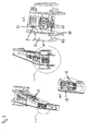
- FIGS. 1 to 3 an embodiment of an excavator handle according to the invention is shown.
- the excavator handle has a box section of a top flange 3, a bottom flange 4 and a first side plate 1 and a second side plate 2.
- the respective sheets are welded together and thus form a welded construction.
- the interior of the box profile is now over a plurality of recesses 5 to 13, which in the longitudinal direction of the excavator handle in a row in the side plates 1 and 2 and in the top and bottom 3 and 4 are arranged, accessible from the outside.
- the arrangement and design of the recesses is in particular in FIG. 2 to recognize.
- the side plates 1 and 2 have, in the vicinity of the articulation region, in which the excavator handle has a large cross-section, initially a very large opening. This is followed by an area with several larger openings 6, which are arranged along the narrower excavator handle in the side panels.
- the openings 6 essentially have the shape of triangles. They are arranged to each other so that the remaining areas of the side plates form struts, which in turn are arranged substantially in the form of triangles to each other.
- smaller recesses 7 are provided. These in turn essentially have the shape of triangles.
- two openings 8 are provided, which serve in particular the better accessibility of this area and which are therefore made larger again.
- the inventive design of the recesses in the side panels which are adapted in size and arrangement to the smaller box profile, the interior of the box section is easily accessible.
- the use of a plurality of recesses results in a structure which, in particular with respect to loads transverse to the longitudinal axis of the boom in the pivoting direction of the excavator handle, has a high rigidity and is also particularly light.
- the upper flange also several recesses are provided, which extend in the longitudinal direction of the excavator handle behind the other along the upper belt.
- a large recess 9 is provided in the articulation area. This extends from the upper belt down to the back of the excavator handle in the articulation region, as this particular FIG. 3 evident.
- the recess 9 is followed by a recess 10 and a further recess 11 in the upper flange.
- the maximum width of the recesses is reduced thereby also decreasing width of the upper belt.
- the upper flange has no recesses to ensure maximum stability.
- Recesses 12 and 13 are again provided at the top of the upper belt, which serve here for accessibility to the interior of the box profile.
- the lower flange 4 has one or more recesses so as to make the interior of the box profile accessible.
- the top and bottom chords are constructed differently with respect to the recesses.
- the side panels have essentially the same recesses. This ensures a symmetrical construction of the excavator handle.
- hydraulic lines 15 are laid in the embodiment in the interior of the box profile. Due to the accessibility of the interior of the box section, these can be laid along the neutral fiber of the excavator handle, i. along the length invariable area of the excavator handle.
- attachment points 14 are provided in the interior of the box structure, on which the hydraulic lines are set.
- the attachment points can be designed as mounting plates, which are welded to the interior of the box structure. It is also conceivable to glue the attachment points inside.
- the open structure of the box profile has the advantage that the access to the hydraulic lines and the attachment points is maintained.
- quick couplings 16 are arranged for the hydraulic lines 15 inside the box profile.
- the quick couplings 16 are located at the top of the excavator handle and are easily accessible via the arranged there recess 8, 12, 13 in the upper flange.
- the quick couplings serve z.
- a coupling arrangement 17 is provided for coupling hydraulic hoses.
- a clamp for continuous hoses may be provided.
- articulation points 30 are provided for articulating the excavator handle to the excavator.
- articulation points 35 are provided for the articulation of the hydraulic cylinder for rocking up and down the excavator handle articulation points 35.
- the articulation points 35 for articulating the hydraulic cylinders are arranged on a tubular element 32, which extends transversely to the longitudinal axis of the excavator handle through it from one side wall to the next.
- this tubular member 32 has recesses 33 through which the hydraulic lines pass in the longitudinal direction of the excavator handle and through which the interior of the tubular member is accessible.
- headlamps 18 and 20 and a camera 19 are arranged inside the box structure.
- the headlights and the camera are aligned by recesses in the lower flange to the outside.
- the (not shown in the drawings) electric cables for supplying or for connecting the headlights and the camera also run inside the box profile.
- the excavator handle according to the invention can also be used without foaming in underwater operation.
- welds 60 may also be provided in the interior of the box profile.
- the box profile is welded from the outside via welds 50, which connect the side walls 1 and 2 and upper and lower chords 3 and 4 together.
- welds 60 also in the interior, the side walls 1 and 2 and upper and lower chords 3 and 4 welded together by welds 60.
- FIG. 4b and shown in the enlarged section A are sealed with only externally welded components of the remaining inside root gap 65 with a sealant 70 so as to protect the root gap 65 from corrosion.
- the welding of the side panels of the upper and lower belt can be provided inside only in partial areas of the excavator handle. The same applies to the sealing of the gap 65.
- the present invention thus provides an excavator handle, which is manufactured by the inventive arrangement of recesses in the side panels and / or in the lower or lower flange in lightweight construction. Due to the accessibility of the interior, this results in a variety of design improvements, which are not possible with closed box sections.
- components which otherwise have to be arranged on the outside of the excavator handle can now be arranged or laid inside the box profile.
- the box section can also be welded from the inside or painted from the inside.
Landscapes
- Engineering & Computer Science (AREA)
- Mechanical Engineering (AREA)
- Mining & Mineral Resources (AREA)
- Civil Engineering (AREA)
- General Engineering & Computer Science (AREA)
- Structural Engineering (AREA)
- Component Parts Of Construction Machinery (AREA)
- Earth Drilling (AREA)
- Jib Cranes (AREA)
- Accessories Of Cameras (AREA)
Applications Claiming Priority (2)
| Application Number | Priority Date | Filing Date | Title |
|---|---|---|---|
| DE202009008478 | 2009-06-19 | ||
| DE202010003617U DE202010003617U1 (de) | 2009-06-19 | 2010-03-17 | Baggerstiel |
Publications (2)
| Publication Number | Publication Date |
|---|---|
| EP2264249A2 true EP2264249A2 (fr) | 2010-12-22 |
| EP2264249A3 EP2264249A3 (fr) | 2014-07-02 |
Family
ID=43028895
Family Applications (1)
| Application Number | Title | Priority Date | Filing Date |
|---|---|---|---|
| EP10005755.3A Withdrawn EP2264249A3 (fr) | 2009-06-19 | 2010-06-02 | Tige de machine d'excavation |
Country Status (5)
| Country | Link |
|---|---|
| US (1) | US20110002765A1 (fr) |
| EP (1) | EP2264249A3 (fr) |
| CN (1) | CN101929170A (fr) |
| DE (2) | DE202010003617U1 (fr) |
| RU (1) | RU2010125202A (fr) |
Families Citing this family (21)
| Publication number | Priority date | Publication date | Assignee | Title |
|---|---|---|---|---|
| CN102140806A (zh) * | 2011-03-22 | 2011-08-03 | 三一重机有限公司 | 一种新型焊接斗杆 |
| US9121163B2 (en) * | 2011-09-20 | 2015-09-01 | Deere & Company | Exoskeleton boom structure |
| ITMI20120206A1 (it) * | 2012-02-14 | 2013-08-15 | Cifa Spa | Segmento di un braccio articolato e braccio articolato comprendente detto segmento |
| CN102587669B (zh) * | 2012-03-21 | 2015-02-18 | 中联重科股份有限公司 | 一种臂架及泵车 |
| KR102391775B1 (ko) * | 2012-08-07 | 2022-04-28 | 셀가드 엘엘씨 | 리튬 이온 배터리용의 개선된 세퍼레이터 막 및 관련 방법 |
| US8944717B2 (en) * | 2012-12-04 | 2015-02-03 | Deere & Company | Integrated pivot pin lubricator |
| DE102014108768B4 (de) * | 2013-06-28 | 2025-01-16 | Kubota Corporation | Ausleger für eine Arbeitsmaschine |
| CN104153417A (zh) * | 2014-07-13 | 2014-11-19 | 李志勇 | 一种管线架梁结构 |
| DE102014224462A1 (de) * | 2014-11-28 | 2016-06-02 | Putzmeister Engineering Gmbh | Mast für eine Arbeitsmaschine und Verfahren zu dessen Herstellung |
| JP6626644B2 (ja) * | 2015-06-29 | 2019-12-25 | キャタピラー エス エー アール エル | 作業機械のブームの補強構造 |
| US10362738B2 (en) * | 2015-09-10 | 2019-07-30 | Komatsu Ltd. | Work vehicle |
| EP3147251A1 (fr) * | 2015-09-25 | 2017-03-29 | Cargotec Patenter AB | Procédé de production d'un élément structurel porteur peint d'un appareil de manipulation de charge destiné à être utilisé sur un véhicule routier |
| CN106088186A (zh) * | 2016-07-22 | 2016-11-09 | 青岛雷沃挖掘机有限公司 | 一种挖掘机用斗杆 |
| US10240318B2 (en) | 2016-12-09 | 2019-03-26 | Caterpillar Inc. | Boom assembly of machine |
| JP6917022B2 (ja) * | 2017-01-31 | 2021-08-11 | 株式会社タグチ工業 | 建設機械のアーム |
| US10676324B2 (en) | 2017-03-05 | 2020-06-09 | Thomas A Weeks | Plug and play tool connection |
| JP6773376B2 (ja) * | 2017-06-29 | 2020-10-21 | 株式会社クボタ | 作業機 |
| US10907326B2 (en) | 2017-08-11 | 2021-02-02 | Deere & Company | Vision system for monitoring a work tool of a work vehicle |
| CN109972676B (zh) * | 2019-05-05 | 2024-06-07 | 徐州徐工矿业机械有限公司 | 一种重载挖掘机动臂 |
| CN112160359A (zh) * | 2020-10-12 | 2021-01-01 | 徐州徐工挖掘机械有限公司 | 工程机械 |
| DE102021106129A1 (de) * | 2021-03-12 | 2022-09-15 | Wacker Neuson Linz Gmbh | Mobile Arbeitsmaschine, insbesondere Bagger, mit einem Fahrzeugrahmen und einem Hubarm |
Citations (1)
| Publication number | Priority date | Publication date | Assignee | Title |
|---|---|---|---|---|
| DE19958696C2 (de) | 1999-11-24 | 2002-03-07 | Liebherr Hydraulikbagger | Industriestiel, insbesondere für Umschlaggeräte |
Family Cites Families (15)
| Publication number | Priority date | Publication date | Assignee | Title |
|---|---|---|---|---|
| US1688664A (en) * | 1926-08-18 | 1928-10-23 | Commw Steel | Dipper handle |
| US3581441A (en) * | 1968-08-09 | 1971-06-01 | W D Gunnels | Surface treatment apparatus |
| US4147263A (en) * | 1977-01-06 | 1979-04-03 | Lull Engineering Company, Inc. | High lift loader with extended transfer |
| US4111320A (en) * | 1977-03-23 | 1978-09-05 | The Warner & Swasey Company | Material handling apparatus having means for connecting material handling tool with a boom |
| US4260322A (en) * | 1978-10-12 | 1981-04-07 | International Harvester Company | Integral box section boom arm |
| GB2049615B (en) * | 1979-05-19 | 1983-04-27 | Orenstein & Koppel Ag | Hydraulic excavator |
| US5806313A (en) * | 1995-11-30 | 1998-09-15 | Caterpillar Inc. | Conduit arrangement for a construction machine |
| DE29705009U1 (de) * | 1997-03-19 | 1997-06-26 | Theodor Klaas GmbH & Co KG, 59387 Ascheberg | Dachdeckerkran mit modular aufgebauten Teleskopschüssen |
| US6409457B1 (en) * | 1999-10-15 | 2002-06-25 | George Korycan | Work vehicle |
| US6823616B1 (en) * | 2001-07-06 | 2004-11-30 | Boskalis Westminister Inc. | Method of excavating |
| JP3822133B2 (ja) * | 2002-05-09 | 2006-09-13 | 株式会社クボタ | 旋回作業機の油圧配管構造 |
| JP3822155B2 (ja) * | 2002-09-24 | 2006-09-13 | 株式会社クボタ | 旋回作業機の掘削装置 |
| US7223062B1 (en) * | 2005-02-23 | 2007-05-29 | Earl William Emerson | Front end loader tactical boom apparatus |
| DE102006005892A1 (de) * | 2006-02-09 | 2007-08-23 | Cnh Baumaschinen Gmbh | Tragarm für eine Arbeitsmaschine |
| US8545163B2 (en) * | 2008-06-26 | 2013-10-01 | Kubota Corporation | Loader work machine |
-
2010
- 2010-03-17 DE DE202010003617U patent/DE202010003617U1/de not_active Expired - Lifetime
- 2010-06-02 EP EP10005755.3A patent/EP2264249A3/fr not_active Withdrawn
- 2010-06-08 DE DE102010022947A patent/DE102010022947A1/de not_active Withdrawn
- 2010-06-11 CN CN2010102007223A patent/CN101929170A/zh active Pending
- 2010-06-18 RU RU2010125202/03A patent/RU2010125202A/ru not_active Application Discontinuation
- 2010-06-21 US US12/819,349 patent/US20110002765A1/en not_active Abandoned
Patent Citations (1)
| Publication number | Priority date | Publication date | Assignee | Title |
|---|---|---|---|---|
| DE19958696C2 (de) | 1999-11-24 | 2002-03-07 | Liebherr Hydraulikbagger | Industriestiel, insbesondere für Umschlaggeräte |
Also Published As
| Publication number | Publication date |
|---|---|
| DE102010022947A1 (de) | 2010-12-23 |
| CN101929170A (zh) | 2010-12-29 |
| RU2010125202A (ru) | 2011-12-27 |
| EP2264249A3 (fr) | 2014-07-02 |
| US20110002765A1 (en) | 2011-01-06 |
| DE202010003617U1 (de) | 2010-10-28 |
Similar Documents
| Publication | Publication Date | Title |
|---|---|---|
| EP2264249A2 (fr) | Tige de machine d'excavation | |
| DE102011102110B4 (de) | Unterwagen für Raupenkran, Raupenkran und Verfahren zum Auf- und Abbau eines Raupenkrans | |
| DE102009016033A1 (de) | Gittermastkran und Gittermastausleger | |
| DE102012012477A1 (de) | Schnellwechselsystem mit Sichtfenster | |
| DE102019119321A1 (de) | Anordnung und verfahren zum bilden eines mastes zum führen eines bohrantriebs in einer hdd-maschine | |
| EP2599923B1 (fr) | Outil de travail avec une console | |
| EP3224430A1 (fr) | Mât pour machine de travail et son procédé de fabrication | |
| DE102007058553A1 (de) | Seitliche Abspannung für einen Gitterausleger eines Kranes | |
| EP4200479B1 (fr) | Unité à changement rapide et système à changement rapide | |
| EP1961691B1 (fr) | Appareil de transbordement | |
| EP0708270B1 (fr) | Chaîne de support de conduites | |
| DE102015001619A1 (de) | Auslegersystem für einen Mobilkran sowie Mobilkran | |
| DE102019126439A1 (de) | Arbeitsgerät, insbesondere Radlader | |
| DE4344395A1 (de) | Säulendrehkran | |
| EP3754117B1 (fr) | Flèche de pelle | |
| DE19702624A1 (de) | Lademaschine mit einer Anlenkkinematik für verschiedene Anbaugeräte, insbesondere Radlager-Kinematik | |
| EP3207193B1 (fr) | Bras de mât et mât distributeur de béton | |
| DE102010053870A1 (de) | Arbeitsmaschine, insbesondere Bagger | |
| EP0218899B2 (fr) | Ciseaux de démolition | |
| DE202011107738U1 (de) | Konstruktionsprofil und Ausleger einer Bootssteganlage | |
| DE2721636A1 (de) | Einrichtung an ladegeraeten mit teleskopisch ausfahrbarem ausleger und mit vom ausleger getragenen hydraulikleitungen | |
| DE3231074C2 (de) | Ausleger für Kräne | |
| DE19713487C1 (de) | Vorrichtung zur Zugentlastung bei Auslegern an Arbeitsausrüstungen von Baggern | |
| DE102020105297A1 (de) | Amphibisches Brückenfahrzeug und Anordnung amphibischer Brückenfahrzeuge | |
| DE102006004207A1 (de) | Gegabelter Ausleger für einen Bagger |
Legal Events
| Date | Code | Title | Description |
|---|---|---|---|
| PUAI | Public reference made under article 153(3) epc to a published international application that has entered the european phase |
Free format text: ORIGINAL CODE: 0009012 |
|
| AK | Designated contracting states |
Kind code of ref document: A2 Designated state(s): AL AT BE BG CH CY CZ DE DK EE ES FI FR GB GR HR HU IE IS IT LI LT LU LV MC MK MT NL NO PL PT RO SE SI SK SM TR |
|
| AX | Request for extension of the european patent |
Extension state: BA ME RS |
|
| PUAL | Search report despatched |
Free format text: ORIGINAL CODE: 0009013 |
|
| AK | Designated contracting states |
Kind code of ref document: A3 Designated state(s): AL AT BE BG CH CY CZ DE DK EE ES FI FR GB GR HR HU IE IS IT LI LT LU LV MC MK MT NL NO PL PT RO SE SI SK SM TR |
|
| AX | Request for extension of the european patent |
Extension state: BA ME RS |
|
| RIC1 | Information provided on ipc code assigned before grant |
Ipc: E02F 3/38 20060101AFI20140528BHEP Ipc: E02F 9/22 20060101ALI20140528BHEP |
|
| STAA | Information on the status of an ep patent application or granted ep patent |
Free format text: STATUS: THE APPLICATION IS DEEMED TO BE WITHDRAWN |
|
| 18D | Application deemed to be withdrawn |
Effective date: 20150106 |