EP2264385B1 - Cycle frigorifique et procédé d'operation d'un cycle frigorifique - Google Patents
Cycle frigorifique et procédé d'operation d'un cycle frigorifique Download PDFInfo
- Publication number
- EP2264385B1 EP2264385B1 EP10181303.8A EP10181303A EP2264385B1 EP 2264385 B1 EP2264385 B1 EP 2264385B1 EP 10181303 A EP10181303 A EP 10181303A EP 2264385 B1 EP2264385 B1 EP 2264385B1
- Authority
- EP
- European Patent Office
- Prior art keywords
- line
- refrigerant
- refrigeration circuit
- compressor unit
- collecting container
- Prior art date
- Legal status (The legal status is an assumption and is not a legal conclusion. Google has not performed a legal analysis and makes no representation as to the accuracy of the status listed.)
- Expired - Lifetime
Links
Images


Classifications
-
- F—MECHANICAL ENGINEERING; LIGHTING; HEATING; WEAPONS; BLASTING
- F25—REFRIGERATION OR COOLING; COMBINED HEATING AND REFRIGERATION SYSTEMS; HEAT PUMP SYSTEMS; MANUFACTURE OR STORAGE OF ICE; LIQUEFACTION SOLIDIFICATION OF GASES
- F25B—REFRIGERATION MACHINES, PLANTS OR SYSTEMS; COMBINED HEATING AND REFRIGERATION SYSTEMS; HEAT PUMP SYSTEMS
- F25B9/00—Compression machines, plants or systems, in which the refrigerant is air or other gas of low boiling point
- F25B9/002—Compression machines, plants or systems, in which the refrigerant is air or other gas of low boiling point characterised by the refrigerant
- F25B9/008—Compression machines, plants or systems, in which the refrigerant is air or other gas of low boiling point characterised by the refrigerant the refrigerant being carbon dioxide
-
- F—MECHANICAL ENGINEERING; LIGHTING; HEATING; WEAPONS; BLASTING
- F25—REFRIGERATION OR COOLING; COMBINED HEATING AND REFRIGERATION SYSTEMS; HEAT PUMP SYSTEMS; MANUFACTURE OR STORAGE OF ICE; LIQUEFACTION SOLIDIFICATION OF GASES
- F25B—REFRIGERATION MACHINES, PLANTS OR SYSTEMS; COMBINED HEATING AND REFRIGERATION SYSTEMS; HEAT PUMP SYSTEMS
- F25B1/00—Compression machines, plants or systems with non-reversible cycle
- F25B1/10—Compression machines, plants or systems with non-reversible cycle with multi-stage compression
-
- F—MECHANICAL ENGINEERING; LIGHTING; HEATING; WEAPONS; BLASTING
- F25—REFRIGERATION OR COOLING; COMBINED HEATING AND REFRIGERATION SYSTEMS; HEAT PUMP SYSTEMS; MANUFACTURE OR STORAGE OF ICE; LIQUEFACTION SOLIDIFICATION OF GASES
- F25B—REFRIGERATION MACHINES, PLANTS OR SYSTEMS; COMBINED HEATING AND REFRIGERATION SYSTEMS; HEAT PUMP SYSTEMS
- F25B40/00—Subcoolers, desuperheaters or superheaters
- F25B40/06—Superheaters
-
- F—MECHANICAL ENGINEERING; LIGHTING; HEATING; WEAPONS; BLASTING
- F25—REFRIGERATION OR COOLING; COMBINED HEATING AND REFRIGERATION SYSTEMS; HEAT PUMP SYSTEMS; MANUFACTURE OR STORAGE OF ICE; LIQUEFACTION SOLIDIFICATION OF GASES
- F25B—REFRIGERATION MACHINES, PLANTS OR SYSTEMS; COMBINED HEATING AND REFRIGERATION SYSTEMS; HEAT PUMP SYSTEMS
- F25B41/00—Fluid-circulation arrangements
- F25B41/20—Disposition of valves, e.g. of on-off valves or flow control valves
-
- F—MECHANICAL ENGINEERING; LIGHTING; HEATING; WEAPONS; BLASTING
- F25—REFRIGERATION OR COOLING; COMBINED HEATING AND REFRIGERATION SYSTEMS; HEAT PUMP SYSTEMS; MANUFACTURE OR STORAGE OF ICE; LIQUEFACTION SOLIDIFICATION OF GASES
- F25B—REFRIGERATION MACHINES, PLANTS OR SYSTEMS; COMBINED HEATING AND REFRIGERATION SYSTEMS; HEAT PUMP SYSTEMS
- F25B9/00—Compression machines, plants or systems, in which the refrigerant is air or other gas of low boiling point
-
- F—MECHANICAL ENGINEERING; LIGHTING; HEATING; WEAPONS; BLASTING
- F25—REFRIGERATION OR COOLING; COMBINED HEATING AND REFRIGERATION SYSTEMS; HEAT PUMP SYSTEMS; MANUFACTURE OR STORAGE OF ICE; LIQUEFACTION SOLIDIFICATION OF GASES
- F25B—REFRIGERATION MACHINES, PLANTS OR SYSTEMS; COMBINED HEATING AND REFRIGERATION SYSTEMS; HEAT PUMP SYSTEMS
- F25B2309/00—Gas cycle refrigeration machines
- F25B2309/06—Compression machines, plants or systems characterised by the refrigerant being carbon dioxide
- F25B2309/061—Compression machines, plants or systems characterised by the refrigerant being carbon dioxide with cycle highest pressure above the supercritical pressure
-
- F—MECHANICAL ENGINEERING; LIGHTING; HEATING; WEAPONS; BLASTING
- F25—REFRIGERATION OR COOLING; COMBINED HEATING AND REFRIGERATION SYSTEMS; HEAT PUMP SYSTEMS; MANUFACTURE OR STORAGE OF ICE; LIQUEFACTION SOLIDIFICATION OF GASES
- F25B—REFRIGERATION MACHINES, PLANTS OR SYSTEMS; COMBINED HEATING AND REFRIGERATION SYSTEMS; HEAT PUMP SYSTEMS
- F25B2400/00—General features or devices for refrigeration machines, plants or systems, combined heating and refrigeration systems or heat-pump systems, i.e. not limited to a particular subgroup of F25B
- F25B2400/07—Details of compressors or related parts
- F25B2400/075—Details of compressors or related parts with parallel compressors
-
- F—MECHANICAL ENGINEERING; LIGHTING; HEATING; WEAPONS; BLASTING
- F25—REFRIGERATION OR COOLING; COMBINED HEATING AND REFRIGERATION SYSTEMS; HEAT PUMP SYSTEMS; MANUFACTURE OR STORAGE OF ICE; LIQUEFACTION SOLIDIFICATION OF GASES
- F25B—REFRIGERATION MACHINES, PLANTS OR SYSTEMS; COMBINED HEATING AND REFRIGERATION SYSTEMS; HEAT PUMP SYSTEMS
- F25B2400/00—General features or devices for refrigeration machines, plants or systems, combined heating and refrigeration systems or heat-pump systems, i.e. not limited to a particular subgroup of F25B
- F25B2400/13—Economisers
-
- F—MECHANICAL ENGINEERING; LIGHTING; HEATING; WEAPONS; BLASTING
- F25—REFRIGERATION OR COOLING; COMBINED HEATING AND REFRIGERATION SYSTEMS; HEAT PUMP SYSTEMS; MANUFACTURE OR STORAGE OF ICE; LIQUEFACTION SOLIDIFICATION OF GASES
- F25B—REFRIGERATION MACHINES, PLANTS OR SYSTEMS; COMBINED HEATING AND REFRIGERATION SYSTEMS; HEAT PUMP SYSTEMS
- F25B2400/00—General features or devices for refrigeration machines, plants or systems, combined heating and refrigeration systems or heat-pump systems, i.e. not limited to a particular subgroup of F25B
- F25B2400/22—Refrigeration systems for supermarkets
-
- F—MECHANICAL ENGINEERING; LIGHTING; HEATING; WEAPONS; BLASTING
- F25—REFRIGERATION OR COOLING; COMBINED HEATING AND REFRIGERATION SYSTEMS; HEAT PUMP SYSTEMS; MANUFACTURE OR STORAGE OF ICE; LIQUEFACTION SOLIDIFICATION OF GASES
- F25B—REFRIGERATION MACHINES, PLANTS OR SYSTEMS; COMBINED HEATING AND REFRIGERATION SYSTEMS; HEAT PUMP SYSTEMS
- F25B2400/00—General features or devices for refrigeration machines, plants or systems, combined heating and refrigeration systems or heat-pump systems, i.e. not limited to a particular subgroup of F25B
- F25B2400/23—Separators
-
- F—MECHANICAL ENGINEERING; LIGHTING; HEATING; WEAPONS; BLASTING
- F25—REFRIGERATION OR COOLING; COMBINED HEATING AND REFRIGERATION SYSTEMS; HEAT PUMP SYSTEMS; MANUFACTURE OR STORAGE OF ICE; LIQUEFACTION SOLIDIFICATION OF GASES
- F25B—REFRIGERATION MACHINES, PLANTS OR SYSTEMS; COMBINED HEATING AND REFRIGERATION SYSTEMS; HEAT PUMP SYSTEMS
- F25B40/00—Subcoolers, desuperheaters or superheaters
- F25B40/02—Subcoolers
-
- F—MECHANICAL ENGINEERING; LIGHTING; HEATING; WEAPONS; BLASTING
- F25—REFRIGERATION OR COOLING; COMBINED HEATING AND REFRIGERATION SYSTEMS; HEAT PUMP SYSTEMS; MANUFACTURE OR STORAGE OF ICE; LIQUEFACTION SOLIDIFICATION OF GASES
- F25B—REFRIGERATION MACHINES, PLANTS OR SYSTEMS; COMBINED HEATING AND REFRIGERATION SYSTEMS; HEAT PUMP SYSTEMS
- F25B40/00—Subcoolers, desuperheaters or superheaters
- F25B40/04—Desuperheaters
-
- F—MECHANICAL ENGINEERING; LIGHTING; HEATING; WEAPONS; BLASTING
- F25—REFRIGERATION OR COOLING; COMBINED HEATING AND REFRIGERATION SYSTEMS; HEAT PUMP SYSTEMS; MANUFACTURE OR STORAGE OF ICE; LIQUEFACTION SOLIDIFICATION OF GASES
- F25B—REFRIGERATION MACHINES, PLANTS OR SYSTEMS; COMBINED HEATING AND REFRIGERATION SYSTEMS; HEAT PUMP SYSTEMS
- F25B49/00—Arrangement or mounting of control or safety devices
- F25B49/02—Arrangement or mounting of control or safety devices for compression type machines, plants or systems
- F25B49/022—Compressor control arrangements
-
- F—MECHANICAL ENGINEERING; LIGHTING; HEATING; WEAPONS; BLASTING
- F25—REFRIGERATION OR COOLING; COMBINED HEATING AND REFRIGERATION SYSTEMS; HEAT PUMP SYSTEMS; MANUFACTURE OR STORAGE OF ICE; LIQUEFACTION SOLIDIFICATION OF GASES
- F25B—REFRIGERATION MACHINES, PLANTS OR SYSTEMS; COMBINED HEATING AND REFRIGERATION SYSTEMS; HEAT PUMP SYSTEMS
- F25B5/00—Compression machines, plants or systems, with several evaporator circuits, e.g. for varying refrigerating capacity
- F25B5/02—Compression machines, plants or systems, with several evaporator circuits, e.g. for varying refrigerating capacity arranged in parallel
Definitions
- the invention relates to a refrigeration cycle in which a one- or multi-component refrigerant circulates, comprising in the flow direction a condenser, a collecting container, an expansion device upstream of an evaporator, an evaporator and a compressor unit.
- the invention relates to a method for operating a refrigeration cycle.
- liquefier should be understood to mean both liquefier and gas cooler.
- Composite refrigerators generally supply a large number of refrigeration consumers, such as refrigerators, refrigerators and freezers. For this purpose circulates in them a one- or multi-component refrigerant or refrigerant mixture.
- a counting of the prior art refrigeration cycle or a refrigeration system in which such a refrigeration cycle is realized, is based on the in the FIG. 1 illustrated embodiment explained in more detail.
- the circulating in the refrigeration cycle one- or multi-component refrigerant is in a condenser or gas cooler A - hereinafter referred to only as a condenser - which is usually outside the supermarket, for example, on the roof, arranged by heat exchange, preferably against outside air, condensed.
- the refrigerant passes through the liquid line D to the cold consumers of the so-called normal cooling circuit.
- the in the FIG. 1 represented consumers F and F 'for any number of consumers of the normal refrigeration cycle.
- Each of the aforementioned refrigeration consumers is preceded by an expansion valve E or E ', in which the refrigerant flowing into the refrigeration appliance or the evaporator or the evaporator of the refrigeration consumer is expanded.
- the so-relaxed refrigerant is evaporated in the evaporators of the refrigerant consumers F and F 'and thus cools the corresponding refrigeration cabinets and rooms.
- the refrigerant evaporated in the refrigeration consumers F and F 'of the normal refrigeration cycle is then fed via the suction line G to the compressor unit H and compressed therein to the desired pressure between 10 and 25 bar.
- the compressor unit H is designed to be single-stage and has several compressors connected in parallel.
- the compressed in the compressor unit H refrigerant is then fed via the pressure line I in turn to the aforementioned condenser A.
- a second liquid line D ' is the condenser C refrigerant supplied to the condenser K and evaporated in this heat exchange with the refrigerant of the still to be explained Tiefkühlniklaufes before it is fed via the line G' of the compressor unit H.
- the liquefied in the condenser K refrigerant of the freezing circuit is supplied via line L to the collector M of the freezing circuit.
- the refrigerant to the consumer P - this is for any number of consumers -, which is preceded by a relaxation device O, supplied and evaporated in this.
- the suction line Q the vaporized refrigerant is fed to the single or multi-stage compressor unit R, compressed in this to a pressure between 25 and 40 bar and then fed via the pressure line S to the aforementioned capacitor K.
- R 404A As a refrigerant of the normal refrigeration cycle, for example, R 404A is used, while for the freezing cycle carbon dioxide is used.
- compressor units H and R, the collector C and M and the capacitor K are usually arranged in a separate machine room.
- about 80 to 90% of the entire pipeline network is located in the sales rooms, the storage areas or other areas of a supermarket accessible to employees and customers.
- this line network operates at pressures of no more than 35 to 40 bar, this is acceptable to the supermarket operators both from a psychological point of view and for cost reasons.
- Object of the present invention is to provide a generic refrigeration cycle and a method for operating a refrigeration cycle, which avoids the disadvantages mentioned.
- a refrigeration cycle which is characterized in that between the condenser and the collecting container, an intermediate-expansion device is arranged.
- the object is achieved in that in the intermediate between the condenser and the collecting intermediate relaxation device, a relaxation of the refrigerant to an (intermediate) pressure of 5 to 40 bar.
- the refrigerator / refrigerator includes a liquid line for conducting liquid refrigerant separated by the gas-liquid separator to the evaporator; and a gas conduit for conducting gaseous refrigerant separated from the gas-liquid separator to an inlet side of the compressor, the gas conduit being in heat exchange with a conduit section between the outlet side of the compressor and an inlet of the condenser.
- a refrigeration cycle, and a method for operating a refrigeration cycle and other embodiments thereof are the same below with reference to in the Figures 2 and 3 shown embodiments explained in more detail, wherein the FIG. 4 shows a refrigeration cycle according to the invention.
- FIG. 2 a composite refrigeration system in which a possible embodiment of a refrigeration cycle is realized.
- a procedure is described in which as a refrigerant HFC (s), HFC (s) or CO 2 can be used.
- the compressed in the compressor unit 6 to a pressure between 10 and 120 bar refrigerant is supplied via the pressure line 7 to the condenser or gas cooler 1 and condensed in this against outside air or deprived.
- the refrigerant is supplied to the refrigerant collector 3 via the lines 2, 2 'and 2 ", but according to the invention it is expanded in the intermediate expansion device a to an intermediate pressure of 5 to 40 bar and the collector 3 need only be designed for a lower pressure position
- the pressure to which the refrigerant in the mentioned intermediate expansion device a is relieved is preferably selected so that it is still below the lowest expected condensing pressure.
- the pressure line 7 with the collecting container 3, preferably with the gas space, connected or connectable can take place, for example, via a connecting line 17, in which an expansion valve h is arranged.
- the pressure line 7 is connected or connectable to the line or line sections 2 or 2 ', 2 "connecting the condenser 1 and the collecting container 3.
- This connection between the pressure line 7 and the line 2 or 2 ', 2 " can be done, for example, via the connecting line 18 shown in dashed lines, in which a valve j is arranged.
- a refrigeration cycle of the collecting container 3 preferably the gas space, connected to the input of the compressor unit 6 or connectable.
- This connection between the collecting container 3 and the input of the compressor unit 6 can, for example, via a connecting line 12, as in the FIG. 2 shown, in the suction line 11 opens, done.
- the selected intermediate pressure can now be kept constant for all operating conditions.
- a regulation is also possible in such a way that there is a constant difference value to the suction pressure. This ensures that the throttle steam fraction at the evaporators is comparatively small, with the result that the liquid and suction lines can be dimensioned correspondingly smaller.
- This also applies to the condensate line, since now no gaseous components have to flow through them back into the condenser 1.
- refrigerant is withdrawn from the collector 3 and the refrigerant consumers or their heat exchangers E2 and E3 supplied. This is preceded by a respective expansion valve b and c, in which the refrigerant flowing into the refrigeration consumer is expanded.
- the refrigerant evaporated in the refrigeration consumers E2 and E3 is then fed back to the compressor unit 6 via the suction line 5 or sucked out of the evaporators E2 and E3 by the latter.
- a portion of the withdrawn from the collector 3 via line 4 refrigerant is fed via line 8 to one or more frozen consumers - represented by the heat exchanger E4 -, which is also preceded by an expansion valve d supplied.
- this partial refrigerant flow is fed via the suction line 9 to the compressor unit 10 and compressed therein to the inlet pressure of the compressor unit 6.
- the thus compressed refrigerant partial stream is then fed via line 11 to the input side of the compressor unit 6.
- a heat exchanger E1 can be connected upstream.
- the heat exchanger E1 is preferably connected on the input side to the output of the condenser 1 or connectable.
- a partial flow of the liquefied or desiccant refrigerant can now be withdrawn from the condenser or gas cooler 1 or line 2 via line 13, in which an expansion valve f is provided, and in the heat exchanger E1 against the heat exchanger E1 to be heated via line 2 'supplied refrigerant to be evaporated.
- the vaporized refrigerant partial stream is then fed via line 14 to a compressor 6 ', which is associated with the above-described compressor unit 6 and which preferably sucks at a higher pressure level, and in this compressed to the desired final pressure of the compressor unit 6.
- the refrigerant stream to be expanded in the intermediate expansion device a is preferably cooled to such an extent that the throttled vapor portion of the expanded refrigerant is minimized.
- the resulting in the collector 3 throttle steam fractions can be sucked off via the line 12 and the dashed line 15 by means of the compressor 6 'at a higher pressure level.
- FIG. 3 1 shows an embodiment of a refrigeration cycle or a method for operating a refrigeration cycle, in which the refrigerant drawn off from the collecting container 3 via the line 4 is subjected to supercooling in the heat exchanger E5.
- the subcooling takes place - in accordance with an advantageous embodiment - in heat exchange with the flash gas withdrawn from the collecting container 3 via line 12.
- Liquid lines such as those in the Figures 2 and 3 shown line 4, with a temperature level below the ambient temperature exposed to heat radiation. This has the consequence that the refrigerant flowing inside the liquid line partially evaporates, thus resulting in the formation of undesirable vapor contents.
- refrigerants are previously undercooled either by an expansion of a partial flow of the refrigerant and subsequent evaporation or by an internal heat transfer to a suction gas stream, which is thereby overheated.
- the temperature difference between the suction and liquid line or the circulating refrigerant therein may be too low to realize an internal heat transfer for the required supercooling of the refrigerant flowing in the liquid line.
- the procedure described thus has the additional advantage that the reliability of the compressor or compressor unit 6 is increased due to a safe overheating of the flash gas stream.
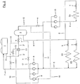
- FIG. 4 shows an embodiment of the refrigeration cycle according to the invention or the method according to the invention for operating a refrigeration cycle. For the sake of clarity is in the FIG. 4 only a part of the in the FIG. 2 and 3 shown refrigerant circuit shown.
- the method according to the invention for operating a refrigeration cycle further develops that at least a partial flow of the flash gas withdrawn from the collecting container is at least temporarily overheated against at least a partial flow of the compressed refrigerant.
- FIG. 4 shows a possible embodiment of the method according to the invention, in which at least temporarily a partial flow of the withdrawn from the reservoir 3 via line 12 flash gas via line 16 to a heat exchanger E6 and superheated in this against the compressed in the compressor unit 6 refrigerant.
- the flash gas stream After passing through the heat exchanger / superheater E6, the flash gas stream is supplied via line 16 'to the inlet of the compressor 6' of the compressor unit 6.
Landscapes
- Engineering & Computer Science (AREA)
- Physics & Mathematics (AREA)
- Mechanical Engineering (AREA)
- Thermal Sciences (AREA)
- General Engineering & Computer Science (AREA)
- Chemical & Material Sciences (AREA)
- Chemical Kinetics & Catalysis (AREA)
- Devices That Are Associated With Refrigeration Equipment (AREA)
- Compression-Type Refrigeration Machines With Reversible Cycles (AREA)
- Air Conditioning Control Device (AREA)
- Air-Conditioning For Vehicles (AREA)
- Separation By Low-Temperature Treatments (AREA)
- Filling Or Discharging Of Gas Storage Vessels (AREA)
- Transmitters (AREA)
- Details Of Measuring And Other Instruments (AREA)
- Cold Air Circulating Systems And Constructional Details In Refrigerators (AREA)
Claims (14)
- Cycle frigorifique, dans lequel un agent réfrigérant à un ou plusieurs composants, en particulier du CO2, circule, dans lequel le cycle frigorifique permet une opération supercritique, présentant dans le sens d'écoulement un condenseur/refroidisseur de gaz (1), un dispositif de détente intermédiaire (a), un récipient de collecte (3), un dispositif de détente (b, c) monté en amont d'un évaporateur (E2, E3), un évaporateur (E2, E3) et une unité compresseur (6) reliée à l'évaporateur (E2, E3) par une conduite d'aspiration (5), dans lequel l'unité compresseur (6) est reliée au condenseur/refroidisseur de gaz (1) au moyen d'une conduite de pression (7), dans lequel la chambre à gaz du récipient de collecte (3) est reliée ou peut être reliée à l'entrée de l'unité compresseur (6) par le biais d'une conduite (12, 16), caractérisé en ce qu'un échangeur de chaleur (E6) est prévu, auquel un flux partiel du gaz flash prélevé du récipient de collecte (3) par le biais de la conduite (12, 16) est amené au moins temporairement et dans lequel ce flux partiel est surchauffé contre l'agent réfrigérant comprimé dans la conduite de pression (7).
- Cycle frigorifique selon la revendication 1, dans lequel le gaz flash après passage par l'échangeur de chaleur/surchauffeur (E6) est amené à l'entrée du compresseur (6') de l'unité compresseur (6) par le biais d'une conduite (16').
- Cycle frigorifique selon la revendication 1 ou 2, dans lequel un échangeur de chaleur (E1) est monté en amont du récipient de collecte (3).
- Cycle frigorifique selon la revendication 3, dans lequel l'échangeur de chaleur (E1) est relié ou peut être relié (2, 13) côté entrée à la sortie du condenseur/refroidisseur de gaz (1).
- Cycle frigorifique selon la revendication 3 ou 4, dans lequel la conduite (2) du condenseur/refroidisseur de gaz (1) se divise en une première section de conduite (2') et en une deuxième section de conduite (13), dans lequel une soupape de détente (f) est agencée dans la deuxième section de conduite (13), et dans lequel l'agent réfrigérant dans la deuxième section de conduite (13) est évaporé dans l'échangeur de chaleur (E1) contre l'agent réfrigérant dans la première section de conduite (2').
- Cycle frigorifique selon la revendication 5, dans lequel la deuxième section de conduite (13, 14) est reliée ou peut être reliée à l'entrée du compresseur (6') de l'unité compresseur (6) après l'échangeur de chaleur (E1).
- Cycle frigorifique selon la revendication 5 ou 6, dans lequel la conduite de pression (7) est reliée ou peut être reliée à la conduite (2, 2', 2'') reliant le condenseur/refroidisseur de gaz (1) et le récipient de collecte (3).
- Cycle frigorifique selon l'une quelconque des revendications 5 à 7, dans lequel la conduite (18) avec une soupape (j), qui y est prévue, relie la première section de conduite (2') après l'échangeur de chaleur (E1) à la conduite de pression (7) après l'unité compresseur (6).
- Cycle frigorifique selon l'une quelconque des revendications précédentes, dans lequel la conduite de pression (7) est reliée ou peut être reliée au récipient de collecte (3), de préférence à sa chambre à gaz.
- Cycle frigorifique selon la revendication 9, dans lequel une soupape de détente (h) est prévue dans la conduite (17), qui relie la conduite de pression (7) au récipient de collecte (3).
- Cycle frigorifique selon l'une quelconque des revendications précédentes, dans lequel l'agent réfrigérant prélevé du récipient de collecte (3) est amené par le biais d'une conduite (8) à un ou plusieurs consommateurs de congélation (E4), auxquels une soupape de détente (d) est montée en amont.
- Cycle frigorifique selon la revendication 11, dans lequel une unité compresseur (10) est prévue, qui est alimentée en agent réfrigérant évaporé dans le consommateur de congélation (E4) par le biais d'une conduite d'aspiration (9), et dans lequel l'agent réfrigérant comprimé dans l'unité compresseur (10) est amené à l'unité compresseur (6) par le biais d'une conduite d'aspiration (11).
- Procédé d'opération d'un cycle frigorifique, dans lequel un agent réfrigérant à un ou plusieurs composants, en particulier du CO2, circule dans le sens d'écoulement à travers un condenseur/refroidisseur de gaz (1), un dispositif de détente intermédiaire (a), un récipient de collecte (3), un dispositif de détente (b, c) monté en amont d'un évaporateur (E2, E3), un évaporateur (E2, E3) et une unité compresseur (6) reliée à l'évaporateur (E2, E3) par une conduite d'aspiration (5), dans lequel du gaz flash est amené de la chambre à gaz du récipient de collecte (3) à l'entrée de l'unité compresseur (6) par le biais d'une conduite (12, 16), caractérisé en ce que dans le dispositif de détente intermédiaire (a) agencé entre le condenseur/refroidisseur de gaz (1) et le récipient de collecte (3), une détente de l'agent réfrigérant à une pression intermédiaire de 5 à 40 bar a lieu, et un flux partiel du gaz flash (12, 16) prélevé du récipient de collecte (3) est surchauffé (E6) au moins temporairement contre l'agent réfrigérant (7) comprimé dans la conduite de pression (7), qui relie l'unité compresseur (6) au condenseur/refroidisseur de gaz (1).
- Procédé selon la revendication 13, dans lequel l'agent réfrigérant (2) est refroidi avant sa détente intermédiaire (a).
Applications Claiming Priority (2)
| Application Number | Priority Date | Filing Date | Title |
|---|---|---|---|
| DE102004038640A DE102004038640A1 (de) | 2004-08-09 | 2004-08-09 | Kältekreislauf und Verfahen zum Betreiben eines Kältekreislaufes |
| EP05775838A EP1789732B1 (fr) | 2004-08-09 | 2005-07-29 | Circuit frigorifique et procede de fonctionnement d'un circuit frigorifique |
Related Parent Applications (2)
| Application Number | Title | Priority Date | Filing Date |
|---|---|---|---|
| EP05775838.5 Division | 2005-07-29 | ||
| EP05775838A Division EP1789732B1 (fr) | 2004-08-09 | 2005-07-29 | Circuit frigorifique et procede de fonctionnement d'un circuit frigorifique |
Publications (3)
| Publication Number | Publication Date |
|---|---|
| EP2264385A2 EP2264385A2 (fr) | 2010-12-22 |
| EP2264385A3 EP2264385A3 (fr) | 2011-10-19 |
| EP2264385B1 true EP2264385B1 (fr) | 2018-04-11 |
Family
ID=34961069
Family Applications (6)
| Application Number | Title | Priority Date | Filing Date |
|---|---|---|---|
| EP05723393A Expired - Lifetime EP1794510B1 (fr) | 2004-08-09 | 2005-02-18 | Circuit de réfrigération à co2 avec sous-refroidissement de l'agent réfrigérant liquide contre la vapeur instantanée de la bouteille accumulatrice et méthode pour exploiter celui-ci |
| EP05715407.2A Expired - Lifetime EP1782001B1 (fr) | 2004-08-09 | 2005-02-18 | Vidange de vapeur instantanée du réservoir d'un circuit refrigérant |
| EP10167202.0A Expired - Lifetime EP2244040B1 (fr) | 2004-08-09 | 2005-07-29 | Vidange de vapeur instantanée du réservoir d'un circuit refrigérant |
| EP10181303.8A Expired - Lifetime EP2264385B1 (fr) | 2004-08-09 | 2005-07-29 | Cycle frigorifique et procédé d'operation d'un cycle frigorifique |
| EP05775838A Expired - Lifetime EP1789732B1 (fr) | 2004-08-09 | 2005-07-29 | Circuit frigorifique et procede de fonctionnement d'un circuit frigorifique |
| EP07020311.2A Expired - Lifetime EP1895246B3 (fr) | 2004-08-09 | 2005-07-29 | Circuit frigorifique et procédé de fonctionnement d'un circuit frigorifique |
Family Applications Before (3)
| Application Number | Title | Priority Date | Filing Date |
|---|---|---|---|
| EP05723393A Expired - Lifetime EP1794510B1 (fr) | 2004-08-09 | 2005-02-18 | Circuit de réfrigération à co2 avec sous-refroidissement de l'agent réfrigérant liquide contre la vapeur instantanée de la bouteille accumulatrice et méthode pour exploiter celui-ci |
| EP05715407.2A Expired - Lifetime EP1782001B1 (fr) | 2004-08-09 | 2005-02-18 | Vidange de vapeur instantanée du réservoir d'un circuit refrigérant |
| EP10167202.0A Expired - Lifetime EP2244040B1 (fr) | 2004-08-09 | 2005-07-29 | Vidange de vapeur instantanée du réservoir d'un circuit refrigérant |
Family Applications After (2)
| Application Number | Title | Priority Date | Filing Date |
|---|---|---|---|
| EP05775838A Expired - Lifetime EP1789732B1 (fr) | 2004-08-09 | 2005-07-29 | Circuit frigorifique et procede de fonctionnement d'un circuit frigorifique |
| EP07020311.2A Expired - Lifetime EP1895246B3 (fr) | 2004-08-09 | 2005-07-29 | Circuit frigorifique et procédé de fonctionnement d'un circuit frigorifique |
Country Status (10)
| Country | Link |
|---|---|
| US (2) | US7644593B2 (fr) |
| EP (6) | EP1794510B1 (fr) |
| KR (2) | KR20070050046A (fr) |
| CN (3) | CN100507402C (fr) |
| AT (1) | ATE544992T1 (fr) |
| AU (2) | AU2005278162A1 (fr) |
| DK (4) | DK1794510T3 (fr) |
| NO (1) | NO343330B1 (fr) |
| RU (1) | RU2362096C2 (fr) |
| WO (1) | WO2006022829A1 (fr) |
Cited By (1)
| Publication number | Priority date | Publication date | Assignee | Title |
|---|---|---|---|---|
| DE102016116028B4 (de) | 2016-07-18 | 2019-12-12 | imbut GmbH | Verfahren zum Fixieren von elektronischen Bauelementen auf einem flexiblen, insbesondere textilen Flächengebilde |
Families Citing this family (58)
| Publication number | Priority date | Publication date | Assignee | Title |
|---|---|---|---|---|
| US20080196420A1 (en) * | 2004-08-09 | 2008-08-21 | Andreas Gernemann | Flashgas Removal From a Receiver in a Refrigeration Circuit |
| US20120117988A1 (en) * | 2006-03-27 | 2012-05-17 | Carrier Corporation | Refrigerating system with parallel staged economizer circuits and a single or two stage main compressor |
| DK2008039T3 (da) | 2006-03-27 | 2017-01-02 | Carrier Corp | Kølesystem med parallelle flertrins-economizer-kredsløb med udledning til en hovedkompressors mellemtrinstryk |
| US8418482B2 (en) * | 2006-03-27 | 2013-04-16 | Carrier Corporation | Refrigerating system with parallel staged economizer circuits using multistage compression |
| CN101460789B (zh) * | 2006-06-01 | 2011-01-26 | 开利公司 | 适于制冷系统的多级压缩机单元 |
| WO2007139554A1 (fr) * | 2006-06-01 | 2007-12-06 | Carrier Corporation | Système et procédé pour un ajustement commandé de soupape de détente |
| WO2008019689A2 (fr) * | 2006-08-18 | 2008-02-21 | Knudsen Køling A/S | Système de réfrigération transcritique doté d'un surpresseur |
| DE102006050232B9 (de) * | 2006-10-17 | 2008-09-18 | Bitzer Kühlmaschinenbau Gmbh | Kälteanlage |
| EP1921399A3 (fr) * | 2006-11-13 | 2010-03-10 | Hussmann Corporation | Système de réfrigération transcritique à deux étapes |
| CN101413738A (zh) * | 2007-10-17 | 2009-04-22 | 开利公司 | 一种中低温集成式冷藏/冷冻系统 |
| JP2009139037A (ja) * | 2007-12-07 | 2009-06-25 | Mitsubishi Heavy Ind Ltd | 冷媒回路 |
| DK2318782T3 (en) * | 2008-07-07 | 2019-04-23 | Carrier Corp | COOLING CIRCUIT |
| DK2313711T3 (da) * | 2008-07-07 | 2013-10-07 | Carrier Corp | Kølekredsløb |
| US8631666B2 (en) | 2008-08-07 | 2014-01-21 | Hill Phoenix, Inc. | Modular CO2 refrigeration system |
| US20120055182A1 (en) | 2008-10-23 | 2012-03-08 | Dube Serge | Co2 refrigeration system |
| ITTV20080140A1 (it) * | 2008-11-04 | 2010-05-05 | Enex Srl | Sistema frigorifero con compressore alternativo ed economizzatore. |
| US20100281914A1 (en) * | 2009-05-07 | 2010-11-11 | Dew Point Control, Llc | Chilled water skid for natural gas processing |
| US20120216551A1 (en) * | 2009-11-03 | 2012-08-30 | E.I. Du Pont De Nemours And Company | Cascade refrigeration system with fluoroolefin refrigerant |
| JP5595025B2 (ja) * | 2009-12-10 | 2014-09-24 | 三菱重工業株式会社 | 空気調和機および空気調和機の冷媒量検出方法 |
| CA2724255C (fr) * | 2010-09-28 | 2011-09-13 | Serge Dube | Systeme de refrigeration au co2 pour surfaces de sports sur glace |
| CN102589217B (zh) * | 2011-01-10 | 2016-02-03 | 珠海格力电器股份有限公司 | 冷媒量控制装置和方法及具有该控制装置的空调机组 |
| EP2663817B1 (fr) * | 2011-01-14 | 2018-10-17 | Carrier Corporation | Système de réfrigération et procédé de fonctionnement d'un système de réfrigération |
| DK177329B1 (en) | 2011-06-16 | 2013-01-14 | Advansor As | Refrigeration system |
| US8863494B2 (en) | 2011-10-06 | 2014-10-21 | Hamilton Sundstrand Space Systems International, Inc. | Turbine outlet frozen gas capture apparatus and method |
| CA2807643C (fr) * | 2012-02-23 | 2017-01-03 | Systemes Lmp Inc. | Sous-refroidissement mecanique de systemes de refrigeration r-744 transcritiques avec recuperation de chaleur et pression de tete flottante de pompe a chaleur |
| EP2841855B1 (fr) * | 2012-04-27 | 2021-04-14 | Carrier Corporation | Système de refroidissement et procédé d'opération dudit système |
| WO2013174379A1 (fr) | 2012-05-22 | 2013-11-28 | Danfoss A/S | Procédé pour actionner une machine frigorifique à compression dans un climat chaud |
| CN104755858A (zh) * | 2012-10-31 | 2015-07-01 | 松下知识产权经营株式会社 | 制冷装置 |
| US9194615B2 (en) | 2013-04-05 | 2015-11-24 | Marc-Andre Lesmerises | CO2 cooling system and method for operating same |
| WO2014179442A1 (fr) | 2013-05-03 | 2014-11-06 | Hill Phoenix, Inc. | Systèmes et procédés de régulation de pression dans un système de réfrigération co2 |
| JP6091399B2 (ja) * | 2013-10-17 | 2017-03-08 | 三菱電機株式会社 | 空気調和装置 |
| US9739200B2 (en) | 2013-12-30 | 2017-08-22 | Rolls-Royce Corporation | Cooling systems for high mach applications |
| EP2889558B1 (fr) | 2013-12-30 | 2019-05-08 | Rolls-Royce Corporation | Système de refroidissement avec machine à expansion et éjecteur |
| US9696074B2 (en) * | 2014-01-03 | 2017-07-04 | Woodward, Inc. | Controlling refrigeration compression systems |
| US9726411B2 (en) * | 2015-03-04 | 2017-08-08 | Heatcraft Refrigeration Products L.L.C. | Modulated oversized compressors configuration for flash gas bypass in a carbon dioxide refrigeration system |
| CA2928553C (fr) | 2015-04-29 | 2023-09-26 | Marc-Andre Lesmerises | Appareil de refroidissement de co2 et methode d'exploitation dudit appareil |
| US10543737B2 (en) | 2015-12-28 | 2020-01-28 | Thermo King Corporation | Cascade heat transfer system |
| US11125483B2 (en) | 2016-06-21 | 2021-09-21 | Hill Phoenix, Inc. | Refrigeration system with condenser temperature differential setpoint control |
| US10352604B2 (en) | 2016-12-06 | 2019-07-16 | Heatcraft Refrigeration Products Llc | System for controlling a refrigeration system with a parallel compressor |
| CN106766297B (zh) * | 2016-12-22 | 2019-08-16 | 广州协义自动化科技有限公司 | 一种能快速恢复平衡压力的超低温水汽捕集泵系统 |
| KR101891993B1 (ko) * | 2017-01-19 | 2018-08-28 | 주식회사 신진에너텍 | 급냉실 냉동실 냉장실의 3단계 냉각 시스템 |
| US10830499B2 (en) * | 2017-03-21 | 2020-11-10 | Heatcraft Refrigeration Products Llc | Transcritical system with enhanced subcooling for high ambient temperature |
| US10648701B2 (en) | 2018-02-06 | 2020-05-12 | Thermo Fisher Scientific (Asheville) Llc | Refrigeration systems and methods using water-cooled condenser and additional water cooling |
| US11022382B2 (en) | 2018-03-08 | 2021-06-01 | Johnson Controls Technology Company | System and method for heat exchanger of an HVAC and R system |
| US10907869B2 (en) | 2018-05-24 | 2021-02-02 | Honeywell International Inc. | Integrated vapor cycle and pumped two-phase cooling system with latent thermal storage of refrigerants for transient thermal management |
| US11796227B2 (en) | 2018-05-24 | 2023-10-24 | Hill Phoenix, Inc. | Refrigeration system with oil control system |
| US11397032B2 (en) | 2018-06-05 | 2022-07-26 | Hill Phoenix, Inc. | CO2 refrigeration system with magnetic refrigeration system cooling |
| US11187445B2 (en) * | 2018-07-02 | 2021-11-30 | Heatcraft Refrigeration Products Llc | Cooling system |
| US10663201B2 (en) | 2018-10-23 | 2020-05-26 | Hill Phoenix, Inc. | CO2 refrigeration system with supercritical subcooling control |
| CN110332635B (zh) * | 2019-07-09 | 2024-03-19 | 珠海格力节能环保制冷技术研究中心有限公司 | 一种双级压缩多补气制冷热泵系统、控制方法和空调器 |
| CN110319613B (zh) * | 2019-07-22 | 2023-05-26 | 北京市京科伦冷冻设备有限公司 | 单级二氧化碳制冷系统 |
| CN114375382B (zh) * | 2019-09-18 | 2023-10-24 | 株式会社日立产机系统 | 热回收装置 |
| US11686513B2 (en) | 2021-02-23 | 2023-06-27 | Johnson Controls Tyco IP Holdings LLP | Flash gas bypass systems and methods for an HVAC system |
| CN114459179B (zh) * | 2021-12-27 | 2023-05-12 | 华北理工大学 | 人工冰场二氧化碳直接蒸发式制冰系统及其使用方法 |
| US12281824B2 (en) | 2022-06-03 | 2025-04-22 | Honeywell International Inc. | Vapor cycle cooling system for high powered devices |
| CN115077114A (zh) * | 2022-06-08 | 2022-09-20 | 松下冷机系统(大连)有限公司 | Co2跨临界船用碳捕集制冷机组 |
| US12487017B2 (en) | 2023-06-02 | 2025-12-02 | Hill Phoenix, Inc. | CO2 refrigeration system with supercritical subcooling control |
| CN119178257B (zh) * | 2024-11-14 | 2025-12-05 | 南京磁谷科技股份有限公司 | 一种复合闪蒸经济器、冷水机组及运行方法 |
Family Cites Families (58)
| Publication number | Priority date | Publication date | Assignee | Title |
|---|---|---|---|---|
| US933682A (en) * | 1908-07-03 | 1909-09-07 | Gardner Tufts Voorhees | Multiple-effect receiver. |
| US1860447A (en) | 1928-07-21 | 1932-05-31 | York Ice Machinery Corp | Refrigeration |
| US2585908A (en) * | 1944-12-19 | 1952-02-19 | Electrolux Ab | Multiple temperature refrigeration system |
| US2680956A (en) * | 1951-12-19 | 1954-06-15 | Haskris Co | Plural stage refrigeration system |
| US3150498A (en) * | 1962-03-08 | 1964-09-29 | Ray Winther Company | Method and apparatus for defrosting refrigeration systems |
| SE395186B (sv) * | 1974-10-11 | 1977-08-01 | Granryd Eric | Sett att forbettra kyleffekt och koldfaktor i en kylanleggning samt kylanleggning for att utova settet |
| US4151724A (en) * | 1977-06-13 | 1979-05-01 | Frick Company | Pressurized refrigerant feed with recirculation for compound compression refrigeration systems |
| JPS5523859A (en) * | 1978-08-08 | 1980-02-20 | Tokyo Shibaura Electric Co | Pluralltemperature refrigeration cycle |
| US5079929A (en) * | 1979-07-31 | 1992-01-14 | Alsenz Richard H | Multi-stage refrigeration apparatus and method |
| FR2513747A1 (fr) * | 1981-09-25 | 1983-04-01 | Satam Brandt Froid | Installation frigorifique a multimotocompresseurs |
| US4430866A (en) * | 1982-09-07 | 1984-02-14 | Emhart Industries, Inc. | Pressure control means for refrigeration systems of the energy conservation type |
| JPS60262A (ja) * | 1983-06-17 | 1985-01-05 | 株式会社日立製作所 | 冷凍サイクル |
| US4947655A (en) * | 1984-01-11 | 1990-08-14 | Copeland Corporation | Refrigeration system |
| US4599873A (en) * | 1984-01-31 | 1986-07-15 | Hyde Robert E | Apparatus for maximizing refrigeration capacity |
| JPS6164526A (ja) * | 1984-09-06 | 1986-04-02 | Nippon Denso Co Ltd | 車両用冷房冷凍装置 |
| DE3440253A1 (de) | 1984-11-03 | 1986-05-15 | Bitzer Kühlmaschinenbau GmbH & Co KG, 7032 Sindelfingen | Kuehlvorrichtung |
| GB8511729D0 (en) * | 1985-05-09 | 1985-06-19 | Svenska Rotor Maskiner Ab | Screw rotor compressor |
| US4621505A (en) | 1985-08-01 | 1986-11-11 | Hussmann Corporation | Flow-through surge receiver |
| US4742694A (en) | 1987-04-17 | 1988-05-10 | Nippondenso Co., Ltd. | Refrigerant apparatus |
| FR2620205A1 (fr) * | 1987-09-04 | 1989-03-10 | Zimmern Bernard | Compresseur hermetique pour refrigeration avec moteur refroidi par gaz d'economiseur |
| US4779427A (en) * | 1988-01-22 | 1988-10-25 | E. Squared Incorporated | Heat actuated heat pump |
| US4831835A (en) | 1988-04-21 | 1989-05-23 | Tyler Refrigeration Corporation | Refrigeration system |
| JPH01318860A (ja) * | 1988-06-20 | 1989-12-25 | Toshiba Corp | 冷凍サイクル装置 |
| US5042268A (en) * | 1989-11-22 | 1991-08-27 | Labrecque James C | Refrigeration |
| US5042262A (en) * | 1990-05-08 | 1991-08-27 | Liquid Carbonic Corporation | Food freezer |
| US5103650A (en) | 1991-03-29 | 1992-04-14 | General Electric Company | Refrigeration systems with multiple evaporators |
| GB2258298B (en) * | 1991-07-31 | 1995-05-17 | Star Refrigeration | Cooling method and apparatus |
| JPH0545007A (ja) * | 1991-08-09 | 1993-02-23 | Nippondenso Co Ltd | 冷凍サイクル |
| US5174123A (en) | 1991-08-23 | 1992-12-29 | Thermo King Corporation | Methods and apparatus for operating a refrigeration system |
| US5191776A (en) * | 1991-11-04 | 1993-03-09 | General Electric Company | Household refrigerator with improved circuit |
| EP0564123A1 (fr) * | 1992-04-02 | 1993-10-06 | Carrier Corporation | Système de réfrigération |
| JPH06159826A (ja) * | 1992-11-24 | 1994-06-07 | Hitachi Ltd | 多段圧縮冷凍装置 |
| DE4309137A1 (de) * | 1993-02-02 | 1994-08-04 | Otfried Dipl Ing Knappe | Verfahren für einen Kälteprozeß und Vorrichtung zur Durchführung desselben |
| DE69414077T2 (de) * | 1993-12-14 | 1999-06-10 | Carrier Corp., Syracuse, N.Y. | Betrieb eines Economisers für Anlagen mit zweistufigem Verdichter |
| JPH07225059A (ja) * | 1994-02-14 | 1995-08-22 | Teruo Kinoshita | 多機能冷凍サイクルシステム |
| JPH085163A (ja) | 1994-06-16 | 1996-01-12 | Mitsubishi Heavy Ind Ltd | 冷凍サイクル装置 |
| US5522233A (en) * | 1994-12-21 | 1996-06-04 | Carrier Corporation | Makeup oil system for first stage oil separation in booster system |
| DE19522884A1 (de) * | 1995-06-23 | 1997-01-02 | Inst Luft Kaeltetech Gem Gmbh | Verfahren zum Betrieb einer Kompressionskälteanlage |
| FR2738331B1 (fr) * | 1995-09-01 | 1997-11-21 | Profroid Ind Sa | Dispositif d'optimisation energetique d'un ensemble de refrigeration a compression et a detente directe |
| NO970066D0 (no) * | 1997-01-08 | 1997-01-08 | Norild As | Kuldeanlegg med lukket sirkulasjonskrets |
| JPH1163694A (ja) * | 1997-08-21 | 1999-03-05 | Zexel Corp | 冷却サイクル |
| JP2000154941A (ja) * | 1998-11-19 | 2000-06-06 | Matsushita Electric Ind Co Ltd | 冷凍装置 |
| ES2265187T3 (es) | 1999-02-17 | 2007-02-01 | Yanmar Co., Ltd. | Circuito de sobreenfriamiento con refrigerante. |
| EP1046869B1 (fr) * | 1999-04-20 | 2005-02-02 | Sanden Corporation | Système de réfrigération et d'air conditionné |
| DE19920726A1 (de) * | 1999-05-05 | 2000-11-09 | Linde Ag | Kälteanlage |
| DE19944950B4 (de) * | 1999-09-20 | 2008-01-31 | Behr Gmbh & Co. Kg | Klimaanlage mit innerem Wärmeübertrager |
| CN1171050C (zh) * | 1999-09-24 | 2004-10-13 | 三洋电机株式会社 | 多级压缩制冷装置 |
| US6276148B1 (en) * | 2000-02-16 | 2001-08-21 | David N. Shaw | Boosted air source heat pump |
| WO2002023105A1 (fr) | 2000-09-15 | 2002-03-21 | Mile High Equipment Company | Machine a glace silencieuse |
| US6385980B1 (en) * | 2000-11-15 | 2002-05-14 | Carrier Corporation | High pressure regulation in economized vapor compression cycles |
| JP2002156161A (ja) * | 2000-11-16 | 2002-05-31 | Mitsubishi Heavy Ind Ltd | 空気調和装置 |
| US6470693B1 (en) * | 2001-07-11 | 2002-10-29 | Ingersoll-Rand Company | Compressed air refrigeration system |
| JP3603848B2 (ja) * | 2001-10-23 | 2004-12-22 | ダイキン工業株式会社 | 冷凍装置 |
| US6981377B2 (en) * | 2002-02-25 | 2006-01-03 | Outfitter Energy Inc | System and method for generation of electricity and power from waste heat and solar sources |
| JP2003254661A (ja) | 2002-02-27 | 2003-09-10 | Toshiba Corp | 冷蔵庫 |
| US6694763B2 (en) * | 2002-05-30 | 2004-02-24 | Praxair Technology, Inc. | Method for operating a transcritical refrigeration system |
| DE10258524A1 (de) * | 2002-12-14 | 2004-07-15 | Volkswagen Ag | Kältemittelkreislauf für eine Kfz-Klimaanlage |
| RU33807U1 (ru) * | 2003-07-04 | 2003-11-10 | Государственное Образовательное Учреждение Высшего Профессионального Образования "Омский Государственный Технический Университет" | Холодильная установка |
-
2005
- 2005-02-18 AT AT05723393T patent/ATE544992T1/de active
- 2005-02-18 RU RU2007107807/06A patent/RU2362096C2/ru not_active IP Right Cessation
- 2005-02-18 US US11/659,925 patent/US7644593B2/en not_active Expired - Fee Related
- 2005-02-18 CN CNB2005800267473A patent/CN100507402C/zh not_active Expired - Fee Related
- 2005-02-18 DK DK05723393.4T patent/DK1794510T3/da active
- 2005-02-18 WO PCT/US2005/005413 patent/WO2006022829A1/fr not_active Ceased
- 2005-02-18 EP EP05723393A patent/EP1794510B1/fr not_active Expired - Lifetime
- 2005-02-18 KR KR1020077003139A patent/KR20070050046A/ko not_active Withdrawn
- 2005-02-18 EP EP05715407.2A patent/EP1782001B1/fr not_active Expired - Lifetime
- 2005-02-18 AU AU2005278162A patent/AU2005278162A1/en not_active Abandoned
- 2005-07-29 KR KR1020077003141A patent/KR20070046847A/ko not_active Withdrawn
- 2005-07-29 EP EP10167202.0A patent/EP2244040B1/fr not_active Expired - Lifetime
- 2005-07-29 DK DK10181303.8T patent/DK2264385T3/en active
- 2005-07-29 EP EP10181303.8A patent/EP2264385B1/fr not_active Expired - Lifetime
- 2005-07-29 DK DK10167202T patent/DK2244040T3/da active
- 2005-07-29 EP EP05775838A patent/EP1789732B1/fr not_active Expired - Lifetime
- 2005-07-29 AU AU2005270472A patent/AU2005270472B2/en not_active Ceased
- 2005-07-29 DK DK07020311.2T patent/DK1895246T6/da active
- 2005-07-29 CN CN2009102463806A patent/CN101713596B/zh not_active Expired - Lifetime
- 2005-07-29 US US11/659,926 patent/US8113008B2/en active Active
- 2005-07-29 EP EP07020311.2A patent/EP1895246B3/fr not_active Expired - Lifetime
- 2005-07-29 CN CN200580026836A patent/CN100582603C/zh not_active Expired - Lifetime
-
2007
- 2007-03-06 NO NO20071229A patent/NO343330B1/no unknown
Non-Patent Citations (1)
| Title |
|---|
| None * |
Cited By (1)
| Publication number | Priority date | Publication date | Assignee | Title |
|---|---|---|---|---|
| DE102016116028B4 (de) | 2016-07-18 | 2019-12-12 | imbut GmbH | Verfahren zum Fixieren von elektronischen Bauelementen auf einem flexiblen, insbesondere textilen Flächengebilde |
Also Published As
Similar Documents
| Publication | Publication Date | Title |
|---|---|---|
| EP2264385B1 (fr) | Cycle frigorifique et procédé d'operation d'un cycle frigorifique | |
| DE102004038640A1 (de) | Kältekreislauf und Verfahen zum Betreiben eines Kältekreislaufes | |
| DE112004002189T5 (de) | Kühlsystem mit Verdampfer und Verdichter | |
| EP3099985B1 (fr) | Système de réfrigération | |
| DE102020121275B4 (de) | Wärmeübertrager eines Kältemittelkreislaufes einer Fahrzeugklimaanlage | |
| EP1050726B1 (fr) | Système frigorifique | |
| DE102019111309A1 (de) | Ejektor-basiertes Kühlungssystem und Kühlungsverfahren | |
| EP1498673B1 (fr) | Système de dégivrage par gaz chaud pour installations de réfrigération | |
| DE102007043162B4 (de) | Klimaanlage mit automatischer Kältemittelverlagerung | |
| DE102011012644A1 (de) | Kälteanlage | |
| DE10233411B4 (de) | Kälteanlage mit wenigstens einem Kältekreislauf und Verfahren zum Abtauen des oder der Kälteverbraucher einer Kälteanlage | |
| AT509647A2 (de) | Transkritisches co2 wärme-kälte-verbundsystem | |
| WO2011097748A2 (fr) | Pompe à chaleur | |
| EP1050723B1 (fr) | Système frigorifique et procédé de fonctionnement d'un système frigorifique | |
| CH665708A5 (de) | Verfahren zum betreiben eines kaeltemittelkreislaufs und kaeltemittelkreislauf zur durchfuehrung des verfahrens. | |
| EP1050724A2 (fr) | Système frigorifique | |
| DE102012004801A1 (de) | Anordnung für eine Wärmepumpe mit Schraubenverdichter | |
| WO2005075901A1 (fr) | Installation frigorifique et procede pour faire fonctionner une installation frigorifique | |
| DE102008013373B4 (de) | Kaskadenkühlvorrichtung und Kaskadenkühlverfahren | |
| WO2025125011A1 (fr) | Détente de pression pour système de réfrigération |
Legal Events
| Date | Code | Title | Description |
|---|---|---|---|
| PUAI | Public reference made under article 153(3) epc to a published international application that has entered the european phase |
Free format text: ORIGINAL CODE: 0009012 |
|
| AC | Divisional application: reference to earlier application |
Ref document number: 1789732 Country of ref document: EP Kind code of ref document: P |
|
| AK | Designated contracting states |
Kind code of ref document: A2 Designated state(s): AT BE BG CH CY CZ DE DK EE ES FI FR GB GR HU IE IS IT LI LT LU LV MC NL PL PT RO SE SI SK TR |
|
| RIN1 | Information on inventor provided before grant (corrected) |
Inventor name: GERNEMANN, ANDREAS Inventor name: HEINBOKEL, BERND Inventor name: SCHIERHORN, UWE |
|
| REG | Reference to a national code |
Ref country code: DE Ref legal event code: R079 Ref document number: 502005015812 Country of ref document: DE Free format text: PREVIOUS MAIN CLASS: F25B0041040000 Ipc: F25B0009000000 |
|
| PUAL | Search report despatched |
Free format text: ORIGINAL CODE: 0009013 |
|
| AK | Designated contracting states |
Kind code of ref document: A3 Designated state(s): AT BE BG CH CY CZ DE DK EE ES FI FR GB GR HU IE IS IT LI LT LU LV MC NL PL PT RO SE SI SK TR |
|
| RIC1 | Information provided on ipc code assigned before grant |
Ipc: F25B 9/00 20060101AFI20110914BHEP Ipc: F25B 40/06 20060101ALI20110914BHEP |
|
| 17P | Request for examination filed |
Effective date: 20120320 |
|
| GRAP | Despatch of communication of intention to grant a patent |
Free format text: ORIGINAL CODE: EPIDOSNIGR1 |
|
| INTG | Intention to grant announced |
Effective date: 20170918 |
|
| GRAS | Grant fee paid |
Free format text: ORIGINAL CODE: EPIDOSNIGR3 |
|
| GRAJ | Information related to disapproval of communication of intention to grant by the applicant or resumption of examination proceedings by the epo deleted |
Free format text: ORIGINAL CODE: EPIDOSDIGR1 |
|
| GRAL | Information related to payment of fee for publishing/printing deleted |
Free format text: ORIGINAL CODE: EPIDOSDIGR3 |
|
| INTC | Intention to grant announced (deleted) | ||
| GRAP | Despatch of communication of intention to grant a patent |
Free format text: ORIGINAL CODE: EPIDOSNIGR1 |
|
| GRAA | (expected) grant |
Free format text: ORIGINAL CODE: 0009210 |
|
| INTG | Intention to grant announced |
Effective date: 20180219 |
|
| AC | Divisional application: reference to earlier application |
Ref document number: 1789732 Country of ref document: EP Kind code of ref document: P |
|
| AK | Designated contracting states |
Kind code of ref document: B1 Designated state(s): AT BE BG CH CY CZ DE DK EE ES FI FR GB GR HU IE IS IT LI LT LU LV MC NL PL PT RO SE SI SK TR |
|
| REG | Reference to a national code |
Ref country code: GB Ref legal event code: FG4D Free format text: NOT ENGLISH |
|
| REG | Reference to a national code |
Ref country code: CH Ref legal event code: EP |
|
| REG | Reference to a national code |
Ref country code: AT Ref legal event code: REF Ref document number: 988470 Country of ref document: AT Kind code of ref document: T Effective date: 20180415 |
|
| REG | Reference to a national code |
Ref country code: IE Ref legal event code: FG4D Free format text: LANGUAGE OF EP DOCUMENT: GERMAN |
|
| REG | Reference to a national code |
Ref country code: DE Ref legal event code: R096 Ref document number: 502005015812 Country of ref document: DE |
|
| REG | Reference to a national code |
Ref country code: FR Ref legal event code: PLFP Year of fee payment: 14 |
|
| REG | Reference to a national code |
Ref country code: DK Ref legal event code: T3 Effective date: 20180716 |
|
| REG | Reference to a national code |
Ref country code: SE Ref legal event code: TRGR |
|
| REG | Reference to a national code |
Ref country code: NL Ref legal event code: MP Effective date: 20180411 |
|
| REG | Reference to a national code |
Ref country code: LT Ref legal event code: MG4D |
|
| PG25 | Lapsed in a contracting state [announced via postgrant information from national office to epo] |
Ref country code: NL Free format text: LAPSE BECAUSE OF FAILURE TO SUBMIT A TRANSLATION OF THE DESCRIPTION OR TO PAY THE FEE WITHIN THE PRESCRIBED TIME-LIMIT Effective date: 20180411 |
|
| PG25 | Lapsed in a contracting state [announced via postgrant information from national office to epo] |
Ref country code: ES Free format text: LAPSE BECAUSE OF FAILURE TO SUBMIT A TRANSLATION OF THE DESCRIPTION OR TO PAY THE FEE WITHIN THE PRESCRIBED TIME-LIMIT Effective date: 20180411 Ref country code: PL Free format text: LAPSE BECAUSE OF FAILURE TO SUBMIT A TRANSLATION OF THE DESCRIPTION OR TO PAY THE FEE WITHIN THE PRESCRIBED TIME-LIMIT Effective date: 20180411 Ref country code: LT Free format text: LAPSE BECAUSE OF FAILURE TO SUBMIT A TRANSLATION OF THE DESCRIPTION OR TO PAY THE FEE WITHIN THE PRESCRIBED TIME-LIMIT Effective date: 20180411 Ref country code: FI Free format text: LAPSE BECAUSE OF FAILURE TO SUBMIT A TRANSLATION OF THE DESCRIPTION OR TO PAY THE FEE WITHIN THE PRESCRIBED TIME-LIMIT Effective date: 20180411 Ref country code: BG Free format text: LAPSE BECAUSE OF FAILURE TO SUBMIT A TRANSLATION OF THE DESCRIPTION OR TO PAY THE FEE WITHIN THE PRESCRIBED TIME-LIMIT Effective date: 20180711 |
|
| PG25 | Lapsed in a contracting state [announced via postgrant information from national office to epo] |
Ref country code: LV Free format text: LAPSE BECAUSE OF FAILURE TO SUBMIT A TRANSLATION OF THE DESCRIPTION OR TO PAY THE FEE WITHIN THE PRESCRIBED TIME-LIMIT Effective date: 20180411 Ref country code: GR Free format text: LAPSE BECAUSE OF FAILURE TO SUBMIT A TRANSLATION OF THE DESCRIPTION OR TO PAY THE FEE WITHIN THE PRESCRIBED TIME-LIMIT Effective date: 20180712 |
|
| PG25 | Lapsed in a contracting state [announced via postgrant information from national office to epo] |
Ref country code: PT Free format text: LAPSE BECAUSE OF FAILURE TO SUBMIT A TRANSLATION OF THE DESCRIPTION OR TO PAY THE FEE WITHIN THE PRESCRIBED TIME-LIMIT Effective date: 20180813 |
|
| REG | Reference to a national code |
Ref country code: DE Ref legal event code: R097 Ref document number: 502005015812 Country of ref document: DE |
|
| PG25 | Lapsed in a contracting state [announced via postgrant information from national office to epo] |
Ref country code: SK Free format text: LAPSE BECAUSE OF FAILURE TO SUBMIT A TRANSLATION OF THE DESCRIPTION OR TO PAY THE FEE WITHIN THE PRESCRIBED TIME-LIMIT Effective date: 20180411 Ref country code: EE Free format text: LAPSE BECAUSE OF FAILURE TO SUBMIT A TRANSLATION OF THE DESCRIPTION OR TO PAY THE FEE WITHIN THE PRESCRIBED TIME-LIMIT Effective date: 20180411 Ref country code: RO Free format text: LAPSE BECAUSE OF FAILURE TO SUBMIT A TRANSLATION OF THE DESCRIPTION OR TO PAY THE FEE WITHIN THE PRESCRIBED TIME-LIMIT Effective date: 20180411 Ref country code: CZ Free format text: LAPSE BECAUSE OF FAILURE TO SUBMIT A TRANSLATION OF THE DESCRIPTION OR TO PAY THE FEE WITHIN THE PRESCRIBED TIME-LIMIT Effective date: 20180411 |
|
| PLBE | No opposition filed within time limit |
Free format text: ORIGINAL CODE: 0009261 |
|
| STAA | Information on the status of an ep patent application or granted ep patent |
Free format text: STATUS: NO OPPOSITION FILED WITHIN TIME LIMIT |
|
| PG25 | Lapsed in a contracting state [announced via postgrant information from national office to epo] |
Ref country code: IT Free format text: LAPSE BECAUSE OF FAILURE TO SUBMIT A TRANSLATION OF THE DESCRIPTION OR TO PAY THE FEE WITHIN THE PRESCRIBED TIME-LIMIT Effective date: 20180411 |
|
| REG | Reference to a national code |
Ref country code: CH Ref legal event code: PL |
|
| 26N | No opposition filed |
Effective date: 20190114 |
|
| PG25 | Lapsed in a contracting state [announced via postgrant information from national office to epo] |
Ref country code: LU Free format text: LAPSE BECAUSE OF NON-PAYMENT OF DUE FEES Effective date: 20180729 Ref country code: MC Free format text: LAPSE BECAUSE OF FAILURE TO SUBMIT A TRANSLATION OF THE DESCRIPTION OR TO PAY THE FEE WITHIN THE PRESCRIBED TIME-LIMIT Effective date: 20180411 |
|
| REG | Reference to a national code |
Ref country code: BE Ref legal event code: MM Effective date: 20180731 |
|
| PG25 | Lapsed in a contracting state [announced via postgrant information from national office to epo] |
Ref country code: CH Free format text: LAPSE BECAUSE OF NON-PAYMENT OF DUE FEES Effective date: 20180731 Ref country code: LI Free format text: LAPSE BECAUSE OF NON-PAYMENT OF DUE FEES Effective date: 20180731 |
|
| REG | Reference to a national code |
Ref country code: IE Ref legal event code: MM4A |
|
| PG25 | Lapsed in a contracting state [announced via postgrant information from national office to epo] |
Ref country code: BE Free format text: LAPSE BECAUSE OF NON-PAYMENT OF DUE FEES Effective date: 20180731 Ref country code: SI Free format text: LAPSE BECAUSE OF FAILURE TO SUBMIT A TRANSLATION OF THE DESCRIPTION OR TO PAY THE FEE WITHIN THE PRESCRIBED TIME-LIMIT Effective date: 20180411 |
|
| PG25 | Lapsed in a contracting state [announced via postgrant information from national office to epo] |
Ref country code: IE Free format text: LAPSE BECAUSE OF NON-PAYMENT OF DUE FEES Effective date: 20180729 |
|
| REG | Reference to a national code |
Ref country code: AT Ref legal event code: MM01 Ref document number: 988470 Country of ref document: AT Kind code of ref document: T Effective date: 20180729 |
|
| PG25 | Lapsed in a contracting state [announced via postgrant information from national office to epo] |
Ref country code: AT Free format text: LAPSE BECAUSE OF NON-PAYMENT OF DUE FEES Effective date: 20180729 |
|
| PG25 | Lapsed in a contracting state [announced via postgrant information from national office to epo] |
Ref country code: TR Free format text: LAPSE BECAUSE OF FAILURE TO SUBMIT A TRANSLATION OF THE DESCRIPTION OR TO PAY THE FEE WITHIN THE PRESCRIBED TIME-LIMIT Effective date: 20180411 |
|
| PG25 | Lapsed in a contracting state [announced via postgrant information from national office to epo] |
Ref country code: HU Free format text: LAPSE BECAUSE OF FAILURE TO SUBMIT A TRANSLATION OF THE DESCRIPTION OR TO PAY THE FEE WITHIN THE PRESCRIBED TIME-LIMIT; INVALID AB INITIO Effective date: 20050729 |
|
| PG25 | Lapsed in a contracting state [announced via postgrant information from national office to epo] |
Ref country code: CY Free format text: LAPSE BECAUSE OF FAILURE TO SUBMIT A TRANSLATION OF THE DESCRIPTION OR TO PAY THE FEE WITHIN THE PRESCRIBED TIME-LIMIT Effective date: 20180411 |
|
| PG25 | Lapsed in a contracting state [announced via postgrant information from national office to epo] |
Ref country code: IS Free format text: LAPSE BECAUSE OF FAILURE TO SUBMIT A TRANSLATION OF THE DESCRIPTION OR TO PAY THE FEE WITHIN THE PRESCRIBED TIME-LIMIT Effective date: 20180811 |
|
| PGFP | Annual fee paid to national office [announced via postgrant information from national office to epo] |
Ref country code: SE Payment date: 20210623 Year of fee payment: 17 |
|
| REG | Reference to a national code |
Ref country code: SE Ref legal event code: EUG |
|
| PG25 | Lapsed in a contracting state [announced via postgrant information from national office to epo] |
Ref country code: SE Free format text: LAPSE BECAUSE OF NON-PAYMENT OF DUE FEES Effective date: 20220730 |
|
| PGFP | Annual fee paid to national office [announced via postgrant information from national office to epo] |
Ref country code: GB Payment date: 20240620 Year of fee payment: 20 |
|
| PGFP | Annual fee paid to national office [announced via postgrant information from national office to epo] |
Ref country code: DK Payment date: 20240619 Year of fee payment: 20 |
|
| PGFP | Annual fee paid to national office [announced via postgrant information from national office to epo] |
Ref country code: FR Payment date: 20240619 Year of fee payment: 20 |
|
| PGFP | Annual fee paid to national office [announced via postgrant information from national office to epo] |
Ref country code: DE Payment date: 20240619 Year of fee payment: 20 |
|
| REG | Reference to a national code |
Ref country code: DE Ref legal event code: R071 Ref document number: 502005015812 Country of ref document: DE |
|
| REG | Reference to a national code |
Ref country code: DK Ref legal event code: EUP Expiry date: 20250729 |
|
| REG | Reference to a national code |
Ref country code: GB Ref legal event code: PE20 Expiry date: 20250728 |