EP2264400A2 - Rotierende Laseremissionssvorrichtung - Google Patents
Rotierende Laseremissionssvorrichtung Download PDFInfo
- Publication number
- EP2264400A2 EP2264400A2 EP10006050A EP10006050A EP2264400A2 EP 2264400 A2 EP2264400 A2 EP 2264400A2 EP 10006050 A EP10006050 A EP 10006050A EP 10006050 A EP10006050 A EP 10006050A EP 2264400 A2 EP2264400 A2 EP 2264400A2
- Authority
- EP
- European Patent Office
- Prior art keywords
- rotary
- emitting apparatus
- laser emitting
- signal
- laser light
- Prior art date
- Legal status (The legal status is an assumption and is not a legal conclusion. Google has not performed a legal analysis and makes no representation as to the accuracy of the status listed.)
- Withdrawn
Links
- 230000007246 mechanism Effects 0.000 claims abstract description 75
- 230000010363 phase shift Effects 0.000 claims description 16
- 238000004891 communication Methods 0.000 claims description 12
- 230000003287 optical effect Effects 0.000 description 14
- 238000005259 measurement Methods 0.000 description 12
- 230000007704 transition Effects 0.000 description 11
- 230000004907 flux Effects 0.000 description 9
- 230000005855 radiation Effects 0.000 description 8
- 230000007423 decrease Effects 0.000 description 4
- 230000008859 change Effects 0.000 description 3
- 238000001514 detection method Methods 0.000 description 3
- 230000000694 effects Effects 0.000 description 3
- 230000000593 degrading effect Effects 0.000 description 2
- 238000006073 displacement reaction Methods 0.000 description 2
- 238000006243 chemical reaction Methods 0.000 description 1
- ZZUFCTLCJUWOSV-UHFFFAOYSA-N furosemide Chemical compound C1=C(Cl)C(S(=O)(=O)N)=CC(C(O)=O)=C1NCC1=CC=CO1 ZZUFCTLCJUWOSV-UHFFFAOYSA-N 0.000 description 1
- 238000000034 method Methods 0.000 description 1
- 230000010355 oscillation Effects 0.000 description 1
- 238000005070 sampling Methods 0.000 description 1
- 239000004065 semiconductor Substances 0.000 description 1
- 238000007493 shaping process Methods 0.000 description 1
Images


Classifications
-
- G—PHYSICS
- G01—MEASURING; TESTING
- G01C—MEASURING DISTANCES, LEVELS OR BEARINGS; SURVEYING; NAVIGATION; GYROSCOPIC INSTRUMENTS; PHOTOGRAMMETRY OR VIDEOGRAMMETRY
- G01C15/00—Surveying instruments or accessories not provided for in groups G01C1/00 - G01C13/00
- G01C15/002—Active optical surveying means
- G01C15/008—Active optical surveying means combined with inclination sensor
Definitions
- the present invention relates to a rotary laser emitting apparatus which emits laser light while rotating.
- a rotary laser emitting apparatus which emits laser light while rotating about a rotation axis and a receiver which receives the emitted laser light are used to measure a height and a slope angle of a light receiving position against a plane orthogonal to the rotation axis based on signals of the laser light received by the receiver.
- a rotary laser emitting apparatus usually has a structure such as a laser emitting section which is rotatably provided on a foundation and emits the laser light in a direction orthogonal to the rotation axis.
- the rotary laser emitting apparatus is expected to control or suppress an occurrence of shake of the emitted laser light in relation to the rotation axis as much as possible.
- a structure is proposed such that a rotary body is provided rotatably about a rotation axis on a foundation; two or more pentaprisms stacked up on the rotation axis are contained in the rotary body; and a laser light source which emits the laser light to the pentaprisms along the rotation axis is fixedly-provided on the foundation (for example, as shown in Japanese Patent Application Publication No. 2006-71545 ).
- each of the pentaprisms is rotated by the rotary body being rotated on the foundation, and the laser light emitted from the laser light source is emitted so as to pass through each of the rotary pentaprisms; therefore, the laser light is emitted while rotating.
- the occurrence of shake caused from an oscillation by the rotation or the like is controlled by a function of the pentaprisms, each of which deflects the entered light beam in a direction orthogonal to the entered direction and emits the deflected light beam, despite a change in attitude.
- a structure is proposed in which a fixed cylinder is provided around the rotary body; the rotary body is rotated in the fixed cylinder; and a position for mounting the other measurement device is provided on top of the fixed cylinder.
- a vertically continued part is necessary on the fixed cylinder.
- the rotary laser emitting apparatus it is preferable for the rotary laser emitting apparatus to be configured to emit the laser light over the whole circumference in the rotating direction of the rotary body in terms of heightening the accuracy of the measurement along with heightening the convenience of the measurement.
- a structure may be proposed in which a supporting shaft portion extending along the rotation axis of the laser emitting section is provided on the foundation and also a through-hole through which the supporting shaft portion is led is provided on the rotary body; and the position for mounting the other measurement device is provided on top of the supporting shaft portion.
- the laser light emitting section be contained in the rotary body. Since the laser emitting section is contained in the rotary body rotating around the rotation axis, an attitude or an orientation of the rotary body is prone to shake in relation to an axis of the foundation (the rotation axis of the rotary body deviates from the axis of the foundation). Accordingly, the direction of emitted laser light is also prone to shake, and therefore, the accuracy of measurement degrades.
- the present invention aims to provide a rotary laser emitting apparatus having a higher measurement accuracy even when the laser emitting section is provided in an annular rotary body surrounding the rotation axis and the direction of the laser light emitted from the laser emitting section is subject to shake.
- a rotary laser emitting apparatus is configured to include a rotary body, a foundation configured to rotatably support the rotary body about an axis, a laser light emitting section contained in the rotary body and configured to emit laser light in a direction orthogonal to a rotation axis of the rotary body, a relative slope detecting mechanism configured to detect an amount of deviation of the rotation axis of the rotary body from the axis of the foundation as a relative slope signal, and a transmitting section configured to transmit the relative slope signal detected by the relative slope detecting mechanism.
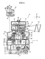
- a rotary laser emitting apparatus 10 includes a rotary body 12, a foundation 11 configured to rotatably support the rotary body 12 about an axis Ra, a laser light emitting section 41 contained in the rotary body 12 and configured to emit laser light in a direction orthogonal to a rotation axis of the rotary body 12, a relative slope detecting mechanism 48 such as a slope sensor configured to detect an amount of deviation of the rotation axis of the rotary body 12 from the axis Ra of the foundation 11 as a relative slope signal, and a transmitting section 47 configured to transmit the relative slope signal detected by the relative slope detecting mechanism 48.
- a relative slope detecting mechanism 48 such as a slope sensor configured to detect an amount of deviation of the rotation axis of the rotary body 12 from the axis Ra of the foundation 11 as a relative slope signal
- a transmitting section 47 configured to transmit the relative slope signal detected by the relative slope detecting mechanism 48.
- the laser light emitting section 41 may have a laser light source 50, for example, a laser diode, as shown in FIG.2 .
- the relative slope signal may be superimposed on the laser light by Phase Shift Keying system.
- the rotary laser emitting apparatus 10 includes the rotary body 12 being rotatably supported on the foundation 11.
- the rotary laser emitting apparatus 10 is positioned on a given point on a survey, and emits the mensurative laser beam Lm as the laser light while rotating at a constant velocity.
- the foundation 11 is a ground portion for when positioning the rotary laser emitting apparatus 10 on the given point, and includes a base portion 13 and a case 14 disposed at the upper side of the base portion 13.
- the base portion 13 is a portion on which a not-illustrated leg portion is positioned for mounting the rotary laser emitting apparatus 10.
- the base portion 13 is in a generally plate-like form, and has an irradiation hole 16 for positioning, which is positioned at a center thereof.
- the base portion 13 supports the case 14 with three screws 16 (only two screws are shown in FIG. 1 ) positioned at three points surrounding the irradiation hole 15 being equally spaced from each other. Among the three screws, one is fixed to the case 14, and the other two are screwed on the case 14 with a changeable screw amount for adjusting height and slope.
- the case 14 includes a discoid bottom wall portion 17 on which each of the screws 16 is screwed, a cylindrical outer wall portion 18 forming an outer shape along with the bottom wall portion 17, and an interior cylindrical portion 19 positioned on the bottom wall portion 17 and inside of the outer wall portion 18.
- a main board 20 is contained in the case 14 and has a function as a controlling section.
- the main board 20 is electrically connected to parts being electrically-driven, and the controlling section overall controls the performance of the electrically-driven parts.
- a positioning irradiation mechanism 21 and a level adjusting mechanisms 22 are provided on the bottom wall portion 17.
- the positioning irradiation mechanism 21 forms an irradiation spot on the axis of the foundation 11 and the level adjusting mechanisms 22 adjusts a slope of the case 14.
- the positioning irradiation mechanism 21 and the level adjusting mechanisms 22 run in accordance with an operation made by an operation portion (not illustrated) under the control of the above-described controlling section 20.
- the positioning irradiation mechanism 21 is provided at the center of the bottom wall portion 17, and has an irradiation source 23, a through-hole 24 and a collimator lens 25.
- the positioning irradiation mechanism 21 is configured to emit laser light from the irradiation source 23 such that the emitted laser light passes through the through-hole 24, the collimator lens 25, and then the irradiation hole 15 provided on the base portion13 to form an irradiation spot (not illustrated) which is used for indicating a reference position for positioning the rotary laser emitting apparatus 10 at a mounting position on a mounting surface.
- An axis of the laser light irradiated by the positioning irradiation mechanism 21 is aligned with an axis of the foundation 11 (of the case 14), that is, the axis Ra as described below. Therefore, the rotary laser emitting apparatus 10 may be easily positioned at the given point by using the irradiation spot (not illustrated) formed by the positioning irradiation mechanism 21.
- the level adjusting mechanisms 22 adjusts a slope of the case 14, that is, a slope of the bottom wall portion 17 in relation to the base portion 13, and is provided corresponding to the two screws 16 (one is not illustrated) which are screwed with changeable screwed amount.
- the level adjusting mechanisms 22 has a structure in which a level adjusting motor 27 is connected to the screws 16 via a gear 26 and by driving the level adjusting motor 27, the screws 16 are rotated to adjust the screwed amount of the screws 16 on the bottom wall portion 17. Therefore, by properly modifying the screwed amount of the two screws 16 (one of them is not illustrated), the slope of the bottom wall portion 17, that is, the slope of the case in relation to the base portion 13 is adjusted.
- the rotary laser emitting apparatus 10 includes a pair of tilt sensors 32 as described below.
- the above-described controlling section 20 obtains an absolute slope signal detected by the pair of tilt sensors and the level adjusting mechanism 22 is automatically driven such that an output from the pair of tilt sensors 32 indicates a horizontal state under the control of the controlling section 20. For this reason, the level adjusting mechanisms 22 and the pair of tilt sensors 32 function as an automatic adjusting mechanism.
- a panel display 28 and a battery storage portion 29 are provided on the outer wall portion 18.
- the panel display 28 displays the information about the rotary laser emitting apparatus 10, and is operated under the control of the controlling section 20.
- the battery storage portion 29 is a space where a battery 30 is stored for an electric power supply within the rotary laser emitting apparatus 10, and is covered by an openable and closable cover plate 31.
- the absolute slope detecting mechanism such as the pair of tilt sensors 32 is provided in the foundation 11 and configured to detect a slope of the axis of the foundation 11 in relation to a horizontal plane as an absolute slope signal, and the transmitting section 47 such as a data transferring mechanism transmits the absolute slope signal detected by the absolute slope detecting mechanism 32 simultaneously with the relative slope signal.
- the pair of tilt sensors 32 is provided in the interior cylindrical portion 19.
- the pair of tilt sensors 32 detects a slope of the interior cylindrical portion 19 in relation to the horizontal plane, that is, an absolute slope of the foundation 11 (an absolute slope of the interior cylindrical portion 19 itself) under the circumstances where the rotary laser emitting apparatus 10 is positioned on the given point for a survey.
- One tilt sensor is configured to detect a tilt about an X-axis; and the other tilt sensor is configured to detect a tilt about a Y-axis. Therefore, the pair of tilt sensors 32 function as the absolute slope detecting mechanism which is configured to detect a slope of the foundation 11 in relation to the horizontal plane.
- the pair of tilt sensors 32 outputs the detected absolute slope signal to the controlling section 20 and also to a drive control board 53 as described below by the data transferring mechanism 47 as described below.
- the rotary laser emitting apparatus 10 may include a wireless communication device 38.
- the transmitting section 47 may transmit the relative slope signal by the wireless communication device 38.
- the interior cylindrical portion 19 has a cylindrical shape overall as described above, and includes a supporting shaft portion 34 (included in the foundation) extending from an upper wall portion 33 located at the upper side of the interior cylindrical portion 19, and also includes a flange portion 35 provided at an intermediate position of the interior cylindrical portion 19.
- the supporting shaft portion 34 has a cylindrical shape, extending along an axis line (aligned to the axis Ra as described below) from the intermediate position of the upper wall portion 33.
- An upper portion of the supporting shaft portion 34 is a mount portion 37 on which in the present embodiment a wireless unit 38 is mounted; and further, an adapter 39 is mounted on top of the wireless unit 38 for attaching, for example, a GPS receiving terminal (not illustrated). Electric wires and the like are led through the supporting shaft portion 34 to connect the wireless unit 38 to the main board 20.
- the flange portion 35 has a flat upper surface to determine a reference plane Bp to be orthogonal to the axis line, and the flange portion 35 is extended from the intermediate position of the interior cylindrical portion 19 to be orthogonal to the axis line (the axis Ra).
- the reference plane Bp determined by the flange portion 35 is set to be parallel to the horizontal plane.
- the rotary body 12 is rotatably supported on the interior cylindrical portion 19.
- the rotary body 12 includes a base section 40 supported on the interior cylindrical portion 19 and a containing section 42 containing a laser emitting section 41.
- the base section 40 has a cylindrical shape, fitting into the upper shape of the interior cylindrical portion 19, and is supported on the interior cylindrical portion 19 rotatably about the axis line of the interior cylindrical portion 19 via a bearing member 43. Therefore, the axis line of the interior cylindrical portion 19 is the axis Ra of the rotary body 12, that is, of the base section 40.
- a direct drive motor hereinafter DD motor 44
- an encoder 45 an electric power transferring mechanism 46, the data transferring mechanism 47, and the slope sensor 48 are provided.
- the base section 40 rotates on the interior cylindrical portion 19 as the DD motor 44 is driven.
- the encoder 45 is provided to detect a relative rotation velocity and rotation amount.
- the electric power is supplied by the electric power transferring mechanism 46 such that the data is exchanged between the base section 40 and the interior cylindrical portion 19 by the data transferring mechanism 47 even while rotating as described above.
- the relative slope detecting mechanism may be provided between the rotary body 12 and the foundation 11.
- the transmitting section may include the laser light source 50 of the laser emitting section 41 and a drive controlling section 53 configured to control the laser light source 50 in accordance with the relative slope signal so as to superimpose the relative slope signal on the laser light emitted from the laser emitting section 41 while the rotary body 12 is rotated.
- the slope sensor 48 is provided to detect the slope of the base section 40 in relation to the interior cylindrical portion 19.
- the slope sensor 48 includes a sensor main unit 48a and a reflecting mirror 48b.
- the sensor main unit 48a is provided on the reference plane Bp determined by the flange portion 35.
- the reflecting mirror 48b is provided to oppose to the sensor main unit 48a (the reference plane Bp) on the bottom of the base section 40.
- the reflecting mirror 48b is set such that a reflecting surface of the reflecting mirror 48b is to be parallel to the reference plane Bp.
- the sensor main unit 48a includes a sensor light source 48c, a sensor optical system 48d, and a sensor receiving section 48e.
- the sensor main unit 48a emits detection light, which is emitted from the sensor light source 48c and then passes through the sensor optical system 48d as a parallel light flux along the orthogonal direction to the reference plane Bp (the direction along the axis Ra).
- the detection light is reflected by the reflecting surface of the reflecting mirror 48b opposing the sensor main unit 48a (the reference plane Bp), again enters the sensor main unit 48a, is guided to the sensor receiving section 48e via the sensor optical system 48d and then is received by the sensor receiving section 48e.
- a position (referred to as "receiving position") where the detection light reflected by the reflecting surface of the reflecting mirror 48b is received is set to be a reference position when the reflection surface of the reflection mirror 48b is parallel to the reference plane Bp, a displacement amount and a displacement direction from the reference position to the receiving position change according to the slope of the reflecting surface of the reflecting mirror 48b in relation to the reference plane Bp. Accordingly, in the slope sensor 48, the slope of the base section 40 in relation to the interior cylindrical portion 19, that is, the relative slope of the rotation body 12 in relation to the foundation 11 is detected by the receiving position of the light at the sensor receiving section 48e.
- the slope sensor 48 functions as the relative slope detecting mechanism which detects an amount of deviation of the rotation axis of the rotary body 12 from the axis Ra as a relative slope signal.
- the slope sensor 48 outputs the detected relative slope signal to the drive control board 53 as described below by the data transferring mechanism 47.
- the containing section 42 is fixed on top of the base section 40 which is to be rotated on the interior cylindrical portion 19.
- the containing section 42 has a hollow cylindrical form, and a through-hole 42c along the axis line is provided at the central portion (close to the axis line) of an upper wall portion 42a and a bottom wall portion 42b.
- the supporting shaft portion 34 extending from the interior cylindrical portion 19 is led through the through-hole 42c, and the upper portion of the supporting shaft portion 34 (the mount portion 37) extrudes from the upper wall portion 42a.
- the laser emitting section 41 is configured to emit laser light from an emitting aperture 49 provided on a side-wall surface 42d of the containing section 42. Therefore, the rotary laser emitting apparatus 10 can emit laser light (the mensurative laser beam Lm) over the whole circumference about the axis Ra by the rotation body 12 rotated on the interior cylindrical portion 19.
- the laser emitting section 41 includes a semiconductor laser diode (hereinafter LD 50), a collimator lens 51, and a beam forming optical system 52.
- An emitted light axis AI of the laser emitting section 41 is set to be parallel to the reference plane Bp determined by the flange portion 35 under the circumstances where the axis line of the rotary body 12 is aligned to the axis Ra.
- the LD 50 is connected to the drive control board 53 (as shown in FIG. 1 ) having a function as a drive controlling section of the laser emitting section 41, and emits the laser light on the emitted light axis AI by being driven by the control of the drive controlling section.
- the collimator lens 51 and the beam forming optical system 52 are provided on the emitted light axis AI.
- the laser light emitted from the LD 50 reaches the collimator lens 51.
- the collimator lens 51 turns the laser light emitted by the LD 50 into the parallel light flux.
- the laser light turned into the parallel light flux through the collimator lens 51 reaches the beam forming optical system 52.
- the beam forming optical system 52 divides the incoming laser light into three beams, and emits each of the divided laser light components so as to form a fan beam.
- the beam forming optical system 52 includes three prism blocks 54a, 54b, 54c for dividing the incoming laser light into three, and three cylindrical lenses 55a, 55b, 55c for forming a fan beam.
- the beam forming optical system 52 has a structure in which the prism blocks 54a, 54b, and 54c are joined in parallel to the reference plane Bp, and in which the cylindrical lenses 55a, 55b, and 55c are joined with the prism blocks 54a, 54b, and 54c, respectively.
- the prism block 54b forms an incoming end face 56 which is positioned on the emitted light axis AI
- the prism block 54b positioned on the emitted light axis AI forms a first emitting end face 57a
- a beam splitter 58a is formed by a joint surface between the prism block 54a and the prism block 54b.
- a beam splitter 58b is formed by a joint surface between the prism block 54b and the prism block 54c.
- a second radiation end face 57b is formed by the prism block 54b. Furthermore, in a direction in which the light flux which is reflected by the beam splitter 58a and then transmits through the beam splitter 58b is directed, a prism reflecting surface 59 is formed by the prism block 54c and a third radiation end face 57c is formed by the prism block 54c in a direction where the light flux is reflected by the prism reflecting surface 59.
- the cylindrical lenses 55 are provided on the radiation end faces 57a, 57b, and 57c, respectively.
- Each of the cylindrical lenses 55 is set so as to turn the parallel light flux emitted from each of the radiation end faces 57a, 57b, and 57c into a so-called fan beam, which is a light flux having a narrow beamwidth in one dimension and a wider beamwidth in the other dimension, the wider beamwidth having a fan-like face shape which spreads out widely, as going away from the axis Ra.
- the laser light passes through the prism block 54b, reaches the beam splitter 58a, and then is divided into two.
- One beam of laser light which is transmitted through the beam splitter 58a passes through the prism block 54a, passes through the first radiation end face 57a and then reaches the cylindrical lens 55a.
- the other laser light beam reflected by the beam splitter 58a passes through the prism block 54b and reaches the beam splitter 58b and is further divided into two.
- One laser light beam reflected by the beam splitter 58b passes through the prism block 54b, passes through the second radiation end face 57b, and reaches the cylindrical lens 55b.
- the other laser light beam which is transmitted through the beam splitter 58b passes through the prism block 54c, reaches the prism reflecting surface 59, then is reflected, passes through the third radiation end face 57c and then reaches the cylindrical lens 55c.
- the fan beam emitted from the cylindrical lens 55a is turned into an irradiation ray Sa along the axis Ra; the fan beam emitted from the cylindrical lens 55c is turned into an irradiation ray Sc spacing a predefined distance from the irradiation ray Sa along the axis Ra (the irradiation directions of the irradiation rays have a relationship such that they have a predefined angle from each other in a horizontal plane); and the fan beam emitted from the cylindrical lens 56b is turned into an irradiation ray Sb which slantingly extends from a top end of one of the irradiation rays Sa and Sc to a bottom end of the other one of the irradiation rays Sa and Sc.
- the irradiation ray Sa, the irradiation ray Sb, and the irradiation ray Sc form an irradiated mensurative laser beam Lm.
- the laser emitting section 41 emits the laser light (the mensurative laser beam Lm) from the emit aperture 49 provided on the side-wall surface 42d of the containing section 42 of the rotary body 12; and therefore, the rotary laser emitting apparatus 10 emits the laser light (the mensurative laser beam Lm) along the reference plane Bp over the whole circumference about the axis Ra by allowing the laser emitting section 41 to emit the laser light, while the rotation body 12 rotates on the interior cyindrical portion 19.
- the mensurative laser beam Lm emitted from the laser emitting section 41 is laser light formed by shaping the laser light emitted from the LD 50 which is driven by the control of the drive controlling section (the drive control board 53).
- the drive controlling section controls the LD 50 so as to make the frequency of the mensurative laser beam Lm modulable to two or more arbitrary frequencies, and as a result, when two or more rotary laser emitting apparatuses are used at the same time, it is possible to distinguish which rotary laser emitting apparatus of the two or more rotary laser emitting apparatuses emits the received mensurative laser beams Lm from the other two or more rotary laser emitting apparatuses.
- the dive controlling section controls a driving of the LD 50 so as to emit the laser light (the mensurative laser beam Lm) having a frequency set by operation of a not-illustrated operation portion.
- the relative slope signal may be superimposed on the laser light by a Phase Shift Keying system.
- the relative slope signal detected by the slope sensor 48 and the absolute slope signal detected by the pair of tilt sensors 32 are superimposed on the mensurative laser beam Lm emitted by the laser emitting section 41.
- the relative slope signal from the slope sensor 48 and the absolute slope signal from the pair of tilt sensors 32 enter the drive controlling section (the drive control board 53).
- the drive controlling section controls the LD 50 so that the obtained relative slope signal and absolute slope signal are superimposed on the mensurative laser beam Lm.
- the drive controlling section controls the LD 50 so that the obtained relative slope signal and absolute slope signal are superimposed by using a Phase Shift Keying System on the mensurative laser beam Lm.
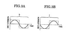
- each signal is an emitting intensity as a function of time.
- each of the signals of "0" and “1" for one period corresponds to the same light amount no matter whether the signal is "0" or "1".
- the drive controlling section converts the obtained relative slope signal and absolute slope signal into data of "0” and “1”, and appropriately combines the signals indicating "0” or “1” to control the drive of the LD 50.
- the laser emitting section 41 Since the laser light emitted from the LD 50 is shaped by the collimator lens 51 and the beam forming optical system 52 as described above and is turned into the mensurative laser beam Lm, the laser emitting section 41 emits the mensurative laser beam Lm on which the relative slope signal and the absolute slope signal are superimposed. Therefore, in the present embodiment, the laser emitting section 41 and the drive controlling section (the drive control board 53) function as the transmitting section which is configured to transmit the relative slope signal and the absolute slope signal.
- the rotary laser emitting apparatus 10 may be used in a survey system including the receiver 60 configured to receive the laser light emitted from the rotary laser emitting apparatus 10 and a calculation mechanism configured to calculate an angle of elevation between a point where the receiver 60 is positioned and a point where the rotary laser emitting apparatus 10 is positioned based on a signal of the laser light received by the receiver 60.
- the receiver 60 receives an alternative current signal of the laser light on which the relative slope signal is superimposed.
- the calculation mechanism is configured to full-wave rectify the received alternative current signal of the laser light and to calculate a barycentric position of the rectified received signals.
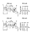
- the survey by using the rotary laser emitting apparatus 10 is described with reference to FIG. 4A to FIG. 4D .
- the rotary laser emitting apparatus 10 is positioned at the given point under the circumstances where no slope is detected by the pair of tilt sensors 32, and the light receiver 60 is positioned at the surveying points.
- the light receiver 60 has a structure which outputs the detected signal of the received light to a calculation mechanism 61.
- the light receiver 60 includes a Si photodiode and an aspheric lens having a directivity of +10-degree.
- the light receiver 60 outputs an electric signal corresponding to the light amount, that is, the signal of the received light to the calculation mechanism 61.
- the calculation mechanism 61 calculates an angle of elevation for the survey based on the signal of the incoming received light.
- the calculation mechanism 61 may be mounted on the inside of the light receiver 60, or may also be mounted on the outside of the light receiver 60 by being electrically connected.
- a position of the surveying point may be surveyed based on the rotary laser emitting apparatus 10 by precisely measuring a time interval of the signals of the received light output from the light receiver 60. Therefore, the rotary laser emitting apparatus 10 and the light receiver 60 and the calculation mechanism 61 function as a survey system.
- the light receiver 60 receives the light of the center position C viewed in the height direction on the mensurative laser beam Lm. Then, as shown in FIG. 4B , the signals of the received light corresponding to the irradiation ray Sa, the irradiation ray Sb, and the irradiation ray Sc are output from the light receiver 60 with equal intervals.
- the light receiver 60 receives the light of the ⁇ v-degree upper position U on the mensurative laser beam Lm in the height direction. Then, as shown in FIG. 4D , the signals of the received light corresponding to the irradiation ray Sa, the irradiation ray Sb, and the irradiation ray Sc are output from the light receiver 60 with differences in time according to intervals on the upper position U.
- the survey system as described above may precisely calculate the angle of elevation at the positioned point where the light receiver 60 is positioned in relation to the given point where the rotary laser emitting apparatus 10 is positioned by precisely measuring the time intervals of the signals of the received light output from the light receiver 60, and may precisely survey the surveying points by calculating a distance and a directionality between the given point and the positioned points.
- the calculation mechanism 61 calculates the angle of elevation at the positioned point where the light receiver 60 is positioned in relation to the given point where the rotary laser emitting apparatus 10 is positioned based on the signal of the light received from the light receiver 60, and calculates the survey value of the surveying points.
- the light receiver 60 obtains a plurality of values (the light amounts) of A/D values as the signals of the received light corresponding to the irradiation ray Sa, Sb, and Sc, which change up and down around 130 of A/D value. This is because a predefined sampling cycle for receiving the mensurative laser beam Lm is set in the light receiver 60, and the light receiver 60 outputs the received value as a digital value (A/D conversion) according to the predefined cycle. Further, the signals of the light received by the light receiver 60 are included in some of groups of values, and the amplitude in the group of values gradually increases then gradually decreases.
- the light receiver 60 outputs the value proportional to the light amount of the received light and since the mensurative laser beam Lm is emitted from the rotating rotary laser emitting apparatus 10, the output values are the largest when the center position of the light receiving portion 60a completely faces the laser emitting section 41 (emit aperture 49) of the rotary laser emitting apparatus 10; and the output values gradually decrease as an angle of between the center position of the light receiving portion 60a and the laser emitting section 41 deviates from each other in the vicinity of the situation where the center position of the light receiving portion 60a completely faces the laser emitting section 41.
- the precise time intervals between the irradiation ray Sa, the irradiation ray Sb, and the irradiation ray Sc are calculated by detecting a barycentric position on each of the three groups of the signals of the light received from the light receiver 60 (as shown in FIG. 6 ).
- the method for detecting a barycentric position by a group of the values a detailed description is omitted since it has been already known.
- FIG. 7 explains the problem by showing an upper view and a lower view with time on horizontal axes corresponding to each other.
- the upper view schematically shows a transition of the signals of the light received from the light receiving portion (the light amount received at the light receiving portion).
- the lower view schematically shows a transition of the light amount of the laser light emitted as the mensurative laser beam.
- a dashed line shows the transition of the signals from the light receiving portion when receiving the rotating mensurative laser beam emitted as laser light having a constant intensity.
- a two-dotted line shows the barycentric position.
- the transition of the signals of the received light indicted with the dashed line shows an ideal transition in perspective of calculating the barycenter, and hereinafter it is called an ideal line.
- the drive controlling section in the same manner as the rotary laser emitting apparatus 10 of the present embodiment as described above, converts the obtained relative slope signal and the absolute slope signal into the data of "0" and "1", and controls the LD so as to combine appropriately the signals indicating "0" or "1” according to the data.
- the problem is that the drive controlling section makes the light amount of the mensurative laser beam Lm zero (stop emitting the laser light from the LD 50) as a signal indicating "0", and makes the light amount of the mensurative laser beam Lm the largest as a signal indicating "1".
- the precise time interval between the three irradiation rays cannot be calculated, and therefore, the angle of elevation between the points where the light receivers are positioned and the given point where the rotary laser emitting apparatus is positioned may not be precisely calculated so that the precise survey result may not be obtained.
- FIG. 8 shows an upper view and a lower view with time on the horizontal axes corresponding to each other for explaining the operation of the rotary laser emitting apparatus 10.
- the upper view schematically shows a transition of the signals of the light received from the light receiving portion (the light amount received at the light receiving portion).
- the lower view schematically shows a transition of the light amount of the laser light emitted as the mensurative laser beam.
- FIG. 9A and FIG. 9B are explanatory views schematically showing an offset mensurative laser beam Lm.
- FIG. 9A shows the signals indicating "0" and "1" on the signals of the received light.
- FIG. 9B shows full-wave rectified values.
- the relative slope signal and the absolute slope signal are superimposed on the mensurative laser beam Lm by using a Phase Shift Keying system as described above, and have the same integral value each other for one period. Therefore, for example, in the same way as described above, when the signal indicating "0" or "1" is formed by controlling the LD 50 to blink, as shown in the lower view of FIG. 8 , an output which changes from zero to the maximum value is a signal indicating "1", and an output which changes from the maximum value to zero is a signal indicating "0".
- either a signal indicating "0" or a signal indicating "1” certainly includes a lighting time period for one period showing one signal, and therefore, it may be prevented from missing the information on the mensurative laser beam Lm so that it is possible to calculate the precise barycentric position (as shown in the upper view of FIG. 8 ).
- the superimposed relative slope signal and absolute slope signal may be easily obtained by judging in the calculation mechanism 61 that if the value on the signals of the received light changes from zero to the maximum value, the signal indicates "1", and that if the value changes from the maximum value to zero, the signal indicates "0".
- the rotary laser emitting apparatus 10 makes the receiver obtain the information on the mensurative laser beam Lm, and also transmits the information on the relative slope signal and the absolute slope signal by making the receiver receive the emitted rotating mensurative laser beam Lm.
- the rotary laser emitting apparatus 10 of the present embodiment offsets the mensurative laser beam Lm emitted from the laser emitting section 41 at a certain output value (hereinafter, reference value) and then, fluctuates the value at an amplitude value being vertically equal from the reference value as a center, and shifts phases of the waveforms of the signals indicating "0" and "1” by 180 degrees (as shown in FIG. 9A ) so as to superimpose the relative slope signal and the absolute slope signal on the mensurative laser beam Lm. Accordingly, the relative slope signal and the absolute slope signal superimposed on the rotating mensurative laser beam Lm emitted from the rotary laser emitting apparatus 10 are so-called alternating current signals centered about the reference value.
- the calculating mechanism 61 is set so as to read out the superimposed relative slope signal and absolute slope signal from the signals of the light received from the light receiver 60, and then to perform a full-wave rectification on the light signals having the reference value as the center, as shown in FIG. 9B , so as to calculate the barycentric position based on the full-wave rectified value. Therefore, the barycentric position is calculated in the calculation mechanism 61 after making the signals indicating "0" and "1" have values larger than the reference value and be equal to each other. As a result, the barycentric position may be more precisely calculated under the same condition as that of signals of received light are received in a case where laser light having a constant or uniform intensity as rotating laser light emitted from the light receiving portion.
- the rotation axis of the rotary body 12 deviates from the axis Ra when the rotary body 12 is rotated on the interior cylindrical portion 19. This is because the laser emitting section 41 is positioned at a position that deviates from the axis Ra in the rotary body 12, and the barycenter shifts with the rotation, and therefore, even if the supporting rigidity of the rotary body 12 on the interior cylindrical portion 19 is heightened, it is difficult to completely eliminate the deviations of the rotation attitude or position of the rotary body 12 on the axis Ra (on the interior cylindrical portion 19). When such deviations occur, the emitted direction of the mensurative laser beam Lm inclines with the deviations, and a precise survey may not be possible since the difference in elevation on the mensurative laser beam Lm is used for the survey as described above.
- the calculation mechanism 61 may modify the signals of the received light (the mensurative laser beam Lm) using the relative and absolute slope signals (may also modify the calculated result therefrom). The relative and absolute slope signals are superimposed on the mensurative laser beam Lm. Then the calculation mechanism 61 may calculate the angle of elevation between the point where the light receiver 60 is positioned and the given point where the rotary laser emitting apparatus 10 is positioned based on the mensurative laser beam Lm so that the precise survey may be performed.
- a high measurement accuracy may be obtained even when the emitted direction of the laser light (the mensurative laser beam Lm) deviates from the axis Ra, which is emitted from the laser emitting section 41 positioned in the rotary body 12 circularly surrounding the axis Ra.
- the relative slope signal (and the absolute slope signal) is transmitted to the light receiver 60 by being superimposed on the mensurative laser beam Lm.
- the relative slope signal (and the absolute slope signal) may be separately transmitted, although this is not limited to the embodiment as described above.
- the absolute slope signal is superimposed on the mensurative laser beam Lm in addition to the relative slope signal.
- the absolute slope signal may not necessarily be superimposed (may not necessarily be in a form to be transmitted), and it is not limited to the embodiment as described above.
- both of the relative slope signal and the absolute slope signal are preferably transmitted.
- the relative slope signal and the absolute slope signal are superimposed by a Phase Shift Keying system on the mensurative laser beam Lm.
- a Phase Shift Keying system it is enough to be able to superimpose the relative slope signal and the absolute slope signal on the mensurative laser beam Lm, and it is not limited to the embodiment as described above.
- the structure as described above is preferably used because if the relative slope signal and the absolute slope signal are superimposed by a Phase Shift Keying system on the mensurative laser beam Lm, the relative slope signal and the absolute slope signal can be superimposed on the mensurative laser beam Lm without affecting the predetermined frequencies even when the mensurative laser beams Lm are set to have arbitrary frequencies.
- a structure is applied such that the relative slope signal and the absolute slope signal are superimposed by a Phase Shift Keying system on the mensurative laser beam Lm, it may be enough to have at least a transmitting section which transmits the information on the relative slope signal, and it is not limited to the embodiment as described above.
- it may be a structure having a wireless communication device as a transmitting section mounted on the rotary laser emitting apparatus and having the relative slope signal from the slope sensor being entered into the controlling section (the main board 20 or the drive control board 53 in the present embodiment) in the rotary laser emitting apparatus.
- the wireless communication device which may transmit the information on the relative slope signal under the control of the controlling section.
- the wireless communication device may also be mounted on the light receiver, and it is necessary to have the structure such that the calculation mechanism of the light receiver modifies the received signal (the mensurative laser beam) (may also be the result of the calculation) based on the information on the relative slope signal which was emitted from the wireless communication device, when it calculates the angle of elevation between the point where the receiver is positioned and the given point where the rotary laser emitting apparatus is positioned.
- the wireless communication device as described above may also preferably transmit the information on the absolute slope signal.
- the rotary laser emitting apparatus of the present embodiment of the present invention even when the attitude or position of the rotary body deviates from the axis, a highly accurate survey result may be obtained because the amount of deviation is informed as the relative slope signal from the transmitting section and the survey result obtained based on the laser light emitted from the laser emitting section is modified based on the relative slope signal. That is to say, it is possible for the rotary laser emitting apparatus to make a survey always have a certain high-level of accuracy no matter whether the attitude of the rotary body deviates from the axis or not.
- the transmitting section includes the laser source of the laser radiation section and the drive controlling section which controls the laser source. Supposing the drive controlling section controls the laser source in accordance with the relative slope signal so that the relative slope signal is superimposed on the laser light emitted from the laser emitting section by rotation of the rotary body, the transmitting section may consist only by updating the control content on the drive controlling section which controls the light source of the laser emitting section. Also, it is possible to prevent the apparatus from becoming large and complex. Further, regarding the light receiver which receives the emitted laser light, it may be enough to update the processing content on the calculation mechanism for processing the received signal, and therefore, it is possible to prevent the apparatus from becoming large and complex.
- the receiver which receives the emitted laser light can appropriately detect the barycentric position on the signals of the received light and can simultaneously obtain the relative slope signal.
- the absolute slope detecting mechanism which detects the slope on the horizontal plane of the foundation is provided on the foundation. Supposing the transmitting section transmits the absolute slope signal detected by the absolute slope detecting mechanism along with the relative slope signal, the receiver which receives the emitted laser light obtains the slope on the horizontal plane of the foundation (the absolute slope signal) in addition to the amount of deviation of the attitude of the rotary body from the axis (the relative slope signal); therefore, a survey result having a higher accuracy is obtained based on the received laser light.
- Supposing the survey system includes the rotary laser emitting apparatus, the receiver which receives the laser light emitted from the rotary laser emitting apparatus, and the calculation mechanism which calculates the angle of elevation between the point where the receiver is positioned and the point where the rotary laser emitting apparatus is positioned based on the signal received from the receiver, wherein the calculation mechanism calculates the barycentric position of the received signal after making the full-wave rectification on the received signal which was turned into the alternating current signal by having the relative slope signal superimposed onto, the calculation mechanism obtains the relative slope signal and the absolute slope signal; accordingly, the barycentric position is more precisely calculated.
- the transmitting section may be a simple structure if a wireless communication device is included, and if the transmitting section transmits the relative slope signal by the wireless communication device.
- the receiver which receives the emitted laser light may also be a simple structure since it may be enough to mount the wireless communication device on the receiver.
Landscapes
- Physics & Mathematics (AREA)
- Engineering & Computer Science (AREA)
- General Physics & Mathematics (AREA)
- Radar, Positioning & Navigation (AREA)
- Remote Sensing (AREA)
- Length Measuring Devices By Optical Means (AREA)
- Optical Radar Systems And Details Thereof (AREA)
- Semiconductor Lasers (AREA)
Applications Claiming Priority (1)
| Application Number | Priority Date | Filing Date | Title |
|---|---|---|---|
| JP2009143901A JP5693827B2 (ja) | 2009-06-17 | 2009-06-17 | 測量システム |
Publications (3)
| Publication Number | Publication Date |
|---|---|
| EP2264400A2 true EP2264400A2 (de) | 2010-12-22 |
| EP2264400A8 EP2264400A8 (de) | 2011-03-09 |
| EP2264400A3 EP2264400A3 (de) | 2013-11-20 |
Family
ID=42767755
Family Applications (1)
| Application Number | Title | Priority Date | Filing Date |
|---|---|---|---|
| EP10006050.8A Withdrawn EP2264400A3 (de) | 2009-06-17 | 2010-06-11 | Rotierende Laseremissionssvorrichtung |
Country Status (4)
| Country | Link |
|---|---|
| US (1) | US8619250B2 (de) |
| EP (1) | EP2264400A3 (de) |
| JP (1) | JP5693827B2 (de) |
| CN (1) | CN101929860B (de) |
Families Citing this family (11)
| Publication number | Priority date | Publication date | Assignee | Title |
|---|---|---|---|---|
| JP5550855B2 (ja) * | 2009-06-12 | 2014-07-16 | 株式会社トプコン | 回転レーザ出射装置 |
| EP2522954A1 (de) * | 2011-05-11 | 2012-11-14 | Leica Geosystems AG | Neigbarer Drehkonstruktionslaser mit Gradmechanismus und Verfahren zur Bestimmung einer Position eines Gradarms des Gradmechanismus |
| US20140111813A1 (en) * | 2012-10-19 | 2014-04-24 | Hamar Laser Instruments, Inc. | Optical assembly and laser alignment apparatus |
| JP6173067B2 (ja) * | 2013-06-25 | 2017-08-02 | 株式会社トプコン | レーザ測量機 |
| JP6266937B2 (ja) * | 2013-09-30 | 2018-01-24 | 株式会社トプコン | 回転レーザ出射装置およびレーザ測量システム |
| CN104700592A (zh) * | 2013-12-06 | 2015-06-10 | 上海诺司纬光电仪器有限公司 | 一种扫平仪控制系统 |
| KR102441844B1 (ko) * | 2015-02-04 | 2022-09-08 | 삼성전자주식회사 | 회전체를 제어하기 위한 방법 및 그 전자 장치 |
| US12152882B2 (en) | 2020-12-01 | 2024-11-26 | Milwaukee Electric Tool Corporation | Laser level systems and controls |
| EP4323722A4 (de) | 2021-04-12 | 2025-03-05 | Milwaukee Electric Tool Corporation | Lasernivelliervorrichtung mit automatischer detektorausrichtung |
| DE112022004570T5 (de) | 2021-12-29 | 2024-07-18 | Milwaukee Electric Tool Corporation | Lasernivellier mit innerer verstellbarer plattform |
| CN114217355B (zh) * | 2022-02-21 | 2022-05-17 | 中国地震局地震研究所 | 一种流动重力仪控制方法及流动重力仪手持终端 |
Citations (1)
| Publication number | Priority date | Publication date | Assignee | Title |
|---|---|---|---|---|
| JP2006071545A (ja) | 2004-09-03 | 2006-03-16 | Topcon Corp | 回転レーザ装置 |
Family Cites Families (18)
| Publication number | Priority date | Publication date | Assignee | Title |
|---|---|---|---|---|
| JP2731644B2 (ja) * | 1991-09-13 | 1998-03-25 | 株式会社ミツトヨ | 光学式寸法測定装置 |
| JP3512469B2 (ja) * | 1994-06-21 | 2004-03-29 | 株式会社トプコン | 測量用装置 |
| JPH0851462A (ja) * | 1994-08-09 | 1996-02-20 | Toshiba Corp | 2相psk信号復調装置 |
| JPH09229686A (ja) * | 1996-02-21 | 1997-09-05 | Laser Technol Inc | データを決定し伝達する装置及び方法 |
| JP3757344B2 (ja) | 1997-02-09 | 2006-03-22 | 株式会社トプコン | 回転レーザー照射装置 |
| US6016455A (en) * | 1997-11-10 | 2000-01-18 | Kabushiki Kaisha Topcon | Automatic control system for construction machinery |
| US6452668B1 (en) * | 1998-10-13 | 2002-09-17 | Arc Second, Inc. | Rotating head optical transmitter for position measurement system |
| JP4614506B2 (ja) * | 2000-07-24 | 2011-01-19 | 株式会社トプコン | 携帯型測距装置 |
| JP4531965B2 (ja) * | 2000-12-04 | 2010-08-25 | 株式会社トプコン | 振れ検出装置、振れ検出装置付き回転レーザ装置及び振れ検出補正装置付き位置測定設定システム |
| JP3799579B2 (ja) * | 2001-12-18 | 2006-07-19 | 株式会社トプコン | 位置測定装置 |
| JP2004212058A (ja) * | 2002-12-26 | 2004-07-29 | Topcon Corp | 作業位置測定装置 |
| CN2601390Y (zh) * | 2003-03-06 | 2004-01-28 | 上海隧道工程股份有限公司 | 微型顶管机的机头姿态激光测量装置 |
| DE102004053249B4 (de) * | 2004-11-04 | 2006-08-17 | Hilti Ag | Baulaser mit neigbarem Umlenkmittel |
| JP4846302B2 (ja) * | 2005-08-30 | 2011-12-28 | 株式会社トプコン | 回転レーザ装置及びこれを用いた回転ブレ検出装置 |
| US7894042B2 (en) * | 2006-01-18 | 2011-02-22 | Lockheed Martin Corporation | Omni-directional imaging sensor |
| JP5020585B2 (ja) * | 2006-09-27 | 2012-09-05 | 株式会社トプコン | 測定システム |
| JP2007271627A (ja) * | 2007-04-26 | 2007-10-18 | Topcon Corp | 作業位置測定装置 |
| JP5145029B2 (ja) * | 2007-12-27 | 2013-02-13 | 株式会社トプコン | 測量機及び測量補正方法 |
-
2009
- 2009-06-17 JP JP2009143901A patent/JP5693827B2/ja not_active Expired - Fee Related
-
2010
- 2010-06-11 EP EP10006050.8A patent/EP2264400A3/de not_active Withdrawn
- 2010-06-15 US US12/815,657 patent/US8619250B2/en not_active Expired - Fee Related
- 2010-06-17 CN CN201010201768.7A patent/CN101929860B/zh not_active Expired - Fee Related
Patent Citations (1)
| Publication number | Priority date | Publication date | Assignee | Title |
|---|---|---|---|---|
| JP2006071545A (ja) | 2004-09-03 | 2006-03-16 | Topcon Corp | 回転レーザ装置 |
Also Published As
| Publication number | Publication date |
|---|---|
| US20100321673A1 (en) | 2010-12-23 |
| EP2264400A8 (de) | 2011-03-09 |
| US8619250B2 (en) | 2013-12-31 |
| JP2011002273A (ja) | 2011-01-06 |
| JP5693827B2 (ja) | 2015-04-01 |
| CN101929860B (zh) | 2013-04-17 |
| CN101929860A (zh) | 2010-12-29 |
| EP2264400A3 (de) | 2013-11-20 |
Similar Documents
| Publication | Publication Date | Title |
|---|---|---|
| US8619250B2 (en) | Rotary laser emitting apparatus | |
| US11486704B2 (en) | Intelligent positioning module | |
| US10982957B2 (en) | Surveying system | |
| US10823558B2 (en) | Surveying instrument | |
| US7081606B2 (en) | Position measuring system | |
| EP2503284B1 (de) | Vermessungssystem mit einer vermessungsvorrichtung, einem vermessungsstab und einer mobilen drahtlosempfänger | |
| US7127822B2 (en) | Surveying instrument | |
| US10371801B2 (en) | Measuring instrument | |
| US10094076B2 (en) | Surveying instrument, surveying instrument usage method, and construction machine control system | |
| US11500096B2 (en) | Surveying instrument | |
| US10330788B2 (en) | Measuring instrument | |
| EP2788715B1 (de) | Robotisches nivellierungsinstrument | |
| US10816665B2 (en) | Surveying system | |
| CN101960256A (zh) | 测量仪器的自动校准 | |
| CN101103249A (zh) | 倾斜检测方法和设备 | |
| US7115852B2 (en) | Photodetection device for rotary laser system | |
| EP3767232B1 (de) | Vorrichtung zur dreidimensionalen vermessung, verfahren zur dreidimensionalen vermessung und programm zur dreidimensionalen vermessung | |
| US20160131473A1 (en) | Shape Measuring Method and Device | |
| US11333496B2 (en) | Surveying instrument | |
| US10884111B2 (en) | Distance measuring apparatus | |
| US10809379B2 (en) | Three-dimensional position measuring system, three-dimensional position measuring method, and measuring module | |
| JP2000234929A (ja) | 中継式自動位置姿勢計測システム | |
| JP4565009B2 (ja) | 測量装置 | |
| JP2006234409A (ja) | 位置計測作図装置 |
Legal Events
| Date | Code | Title | Description |
|---|---|---|---|
| PUAI | Public reference made under article 153(3) epc to a published international application that has entered the european phase |
Free format text: ORIGINAL CODE: 0009012 |
|
| 17P | Request for examination filed |
Effective date: 20100611 |
|
| AK | Designated contracting states |
Kind code of ref document: A2 Designated state(s): AL AT BE BG CH CY CZ DE DK EE ES FI FR GB GR HR HU IE IS IT LI LT LU LV MC MK MT NL NO PL PT RO SE SI SK SM TR |
|
| AX | Request for extension of the european patent |
Extension state: BA ME RS |
|
| RIN1 | Information on inventor provided before grant (corrected) |
Inventor name: KAMIZONO, FUMIHIKO Inventor name: HAYASHI, KUNIHIRO |
|
| PUAL | Search report despatched |
Free format text: ORIGINAL CODE: 0009013 |
|
| AK | Designated contracting states |
Kind code of ref document: A3 Designated state(s): AL AT BE BG CH CY CZ DE DK EE ES FI FR GB GR HR HU IE IS IT LI LT LU LV MC MK MT NL NO PL PT RO SE SI SK SM TR |
|
| AX | Request for extension of the european patent |
Extension state: BA ME RS |
|
| RIC1 | Information provided on ipc code assigned before grant |
Ipc: G01C 15/00 20060101AFI20131015BHEP |
|
| RBV | Designated contracting states (corrected) |
Designated state(s): AL AT BE BG CH CY CZ DE DK EE ES FI FR GB GR HR HU IE IS IT LI LT LU LV MC MK MT NL NO PL PT RO SE SI SK SM TR |
|
| STAA | Information on the status of an ep patent application or granted ep patent |
Free format text: STATUS: THE APPLICATION HAS BEEN WITHDRAWN |
|
| 18W | Application withdrawn |
Effective date: 20160610 |