EP2265362B1 - Mischvorrichtung und verfahren zur herstellung eines präparats mit dieser mischvorrichtung - Google Patents
Mischvorrichtung und verfahren zur herstellung eines präparats mit dieser mischvorrichtung Download PDFInfo
- Publication number
- EP2265362B1 EP2265362B1 EP09726774A EP09726774A EP2265362B1 EP 2265362 B1 EP2265362 B1 EP 2265362B1 EP 09726774 A EP09726774 A EP 09726774A EP 09726774 A EP09726774 A EP 09726774A EP 2265362 B1 EP2265362 B1 EP 2265362B1
- Authority
- EP
- European Patent Office
- Prior art keywords
- rotor
- assembly according
- annular ring
- mixing
- mixture
- Prior art date
- Legal status (The legal status is an assumption and is not a legal conclusion. Google has not performed a legal analysis and makes no representation as to the accuracy of the status listed.)
- Active
Links
Images



Classifications
-
- B—PERFORMING OPERATIONS; TRANSPORTING
- B01—PHYSICAL OR CHEMICAL PROCESSES OR APPARATUS IN GENERAL
- B01F—MIXING, e.g. DISSOLVING, EMULSIFYING OR DISPERSING
- B01F23/00—Mixing according to the phases to be mixed, e.g. dispersing or emulsifying
- B01F23/40—Mixing liquids with liquids; Emulsifying
- B01F23/41—Emulsifying
-
- B—PERFORMING OPERATIONS; TRANSPORTING
- B01—PHYSICAL OR CHEMICAL PROCESSES OR APPARATUS IN GENERAL
- B01F—MIXING, e.g. DISSOLVING, EMULSIFYING OR DISPERSING
- B01F23/00—Mixing according to the phases to be mixed, e.g. dispersing or emulsifying
- B01F23/50—Mixing liquids with solids
- B01F23/53—Mixing liquids with solids using driven stirrers
-
- B—PERFORMING OPERATIONS; TRANSPORTING
- B01—PHYSICAL OR CHEMICAL PROCESSES OR APPARATUS IN GENERAL
- B01F—MIXING, e.g. DISSOLVING, EMULSIFYING OR DISPERSING
- B01F27/00—Mixers with rotary stirring devices in fixed receptacles; Kneaders
- B01F27/80—Mixers with rotary stirring devices in fixed receptacles; Kneaders with stirrers rotating about a substantially vertical axis
- B01F27/81—Mixers with rotary stirring devices in fixed receptacles; Kneaders with stirrers rotating about a substantially vertical axis the stirrers having central axial inflow and substantially radial outflow
- B01F27/812—Mixers with rotary stirring devices in fixed receptacles; Kneaders with stirrers rotating about a substantially vertical axis the stirrers having central axial inflow and substantially radial outflow the stirrers co-operating with surrounding stators, or with intermeshing stators, e.g. comprising slits, orifices or screens
-
- B—PERFORMING OPERATIONS; TRANSPORTING
- B01—PHYSICAL OR CHEMICAL PROCESSES OR APPARATUS IN GENERAL
- B01F—MIXING, e.g. DISSOLVING, EMULSIFYING OR DISPERSING
- B01F35/00—Accessories for mixers; Auxiliary operations or auxiliary devices; Parts or details of general application
- B01F35/71—Feed mechanisms
- B01F35/712—Feed mechanisms for feeding fluids
-
- B—PERFORMING OPERATIONS; TRANSPORTING
- B01—PHYSICAL OR CHEMICAL PROCESSES OR APPARATUS IN GENERAL
- B01F—MIXING, e.g. DISSOLVING, EMULSIFYING OR DISPERSING
- B01F35/00—Accessories for mixers; Auxiliary operations or auxiliary devices; Parts or details of general application
- B01F35/71—Feed mechanisms
- B01F35/717—Feed mechanisms characterised by the means for feeding the components to the mixer
- B01F35/7176—Feed mechanisms characterised by the means for feeding the components to the mixer using pumps
-
- B—PERFORMING OPERATIONS; TRANSPORTING
- B01—PHYSICAL OR CHEMICAL PROCESSES OR APPARATUS IN GENERAL
- B01F—MIXING, e.g. DISSOLVING, EMULSIFYING OR DISPERSING
- B01F35/00—Accessories for mixers; Auxiliary operations or auxiliary devices; Parts or details of general application
- B01F35/71—Feed mechanisms
- B01F35/717—Feed mechanisms characterised by the means for feeding the components to the mixer
- B01F35/718—Feed mechanisms characterised by the means for feeding the components to the mixer using vacuum, under pressure in a closed receptacle or circuit system
-
- B—PERFORMING OPERATIONS; TRANSPORTING
- B01—PHYSICAL OR CHEMICAL PROCESSES OR APPARATUS IN GENERAL
- B01F—MIXING, e.g. DISSOLVING, EMULSIFYING OR DISPERSING
- B01F35/00—Accessories for mixers; Auxiliary operations or auxiliary devices; Parts or details of general application
- B01F35/71—Feed mechanisms
- B01F35/717—Feed mechanisms characterised by the means for feeding the components to the mixer
- B01F35/71805—Feed mechanisms characterised by the means for feeding the components to the mixer using valves, gates, orifices or openings
-
- B—PERFORMING OPERATIONS; TRANSPORTING
- B01—PHYSICAL OR CHEMICAL PROCESSES OR APPARATUS IN GENERAL
- B01F—MIXING, e.g. DISSOLVING, EMULSIFYING OR DISPERSING
- B01F35/00—Accessories for mixers; Auxiliary operations or auxiliary devices; Parts or details of general application
- B01F35/75—Discharge mechanisms
- B01F35/754—Discharge mechanisms characterised by the means for discharging the components from the mixer
- B01F35/7547—Discharge mechanisms characterised by the means for discharging the components from the mixer using valves, gates, orifices or openings
-
- B—PERFORMING OPERATIONS; TRANSPORTING
- B01—PHYSICAL OR CHEMICAL PROCESSES OR APPARATUS IN GENERAL
- B01F—MIXING, e.g. DISSOLVING, EMULSIFYING OR DISPERSING
- B01F2101/00—Mixing characterised by the nature of the mixed materials or by the application field
- B01F2101/06—Mixing of food ingredients
-
- B—PERFORMING OPERATIONS; TRANSPORTING
- B01—PHYSICAL OR CHEMICAL PROCESSES OR APPARATUS IN GENERAL
- B01F—MIXING, e.g. DISSOLVING, EMULSIFYING OR DISPERSING
- B01F2101/00—Mixing characterised by the nature of the mixed materials or by the application field
- B01F2101/21—Mixing of ingredients for cosmetic or perfume compositions
-
- B—PERFORMING OPERATIONS; TRANSPORTING
- B01—PHYSICAL OR CHEMICAL PROCESSES OR APPARATUS IN GENERAL
- B01F—MIXING, e.g. DISSOLVING, EMULSIFYING OR DISPERSING
- B01F2101/00—Mixing characterised by the nature of the mixed materials or by the application field
- B01F2101/22—Mixing of ingredients for pharmaceutical or medical compositions
Definitions
- the invention relates to a mixing assembly comprising a mixing device, a method of manufacturing a preparation.
- This mixing assembly is particularly intended for the manufacture of a preparation, and more particularly for the dispersion of particles in a preparation.
- Such preparations are commonly manufactured for pharmaceutical, cosmetic or agri-food applications.
- the incorporated particles may in particular constitute the active ingredient of the composition and must then be incorporated into the mixture in very precise proportions.
- mixing sets are known. According to the most widespread technology, these comprise a tank, maintained under vacuum and intended to receive the mixture, and a mixing device comprising a rotor comprising mixing blades and cooperating with motor means in order to be rotated. and a stator comprising an annular ring surrounding the rotor and having radial orifices for the passage of the mixture radially projected by said rotor.
- Such mixing devices are known in particular from EP0801974A1 , DE8006977U1 , EP1475143A1 , US 6866411 B1 and US 2002/0110539 A1 .
- the particles are introduced by suction into the tank maintained under vacuum via a supply duct opening at the bottom of the tank, laterally to the rotor-stator unit.
- the supply duct is equipped with a valve for controlling the introduction of the particles into the tank.
- the particles to be incorporated in the mixture circulate in the tank approximately following the path of the arrows f 1.
- the rate of introduction of the powder is directly related to the level of vacuum in the tank.
- a too high vacuum level causes the particles to pass through the mixture too quickly and the particles sucked up against the upper part of the tank; which generates problems of cleaning and product loss.
- the mixing set is equipped with an external piping allowing a re circulation of the preparation.
- the powder particles are introduced into the tank via a supply duct opening into the outer pipework.
- this method poses problems of cleaning the external circulation piping.
- the rate of introduction of the powder is limited by the dimensions of the external piping and by the flow rate of circulation therein.
- the invention aims to improve these devices of the prior art by proposing a mixing assembly for effectively dispersing particles in a mixture, to introduce said particles with a high flow rate and to reduce product losses, and whose cleaning is easy.
- the powder particles are dispersed efficiently because the introduction of the particles is directly carried out in the turbulence zone.
- the rate of introduction of the powders may be greater because it is possible to increase the level of vacuum in such an assembly without the particles being projected against the upper part of the tank.
- the mixing assembly does not require an external circulation tube whose cleaning is difficult.
- mixture assembly according to the invention makes it possible to reduce the time necessary to completely incorporate particles into the preparation.
- the mixing device of the assembly according to the invention comprises a motor block comprising the rotor, the annular ring gear, motor means and a shaft connecting the rotor to the drive means and said engine block supports at least a portion of the supply duct.
- the mixing device is compact and its installation on a mixing set is simple.
- the supply duct is equipped with a valve supported by the engine block.
- the valve is preferably a pneumatic valve with a valve.
- the engine block comprises means for fixing to a mixing tank in order to facilitate the installation of the device on the tank of the mixing unit.
- the fixing means are pressure-tight in order to allow the mixing tank equipped with such a mixing device to be depressurized.
- the supply duct passes through said fixing means to a tank.
- the tank equipped with such a mixing device has only one passage for the installation of the rotor, the annular ring and the supply duct.
- the engine block comprises two coaxial rotors. This embodiment makes it possible to further reduce the production time of the preparation.
- the rotor (s) comprise (s) mixing blades arranged to suck the mixture through the axial orifice of the annular ring and project it radially through the radial orifices of the ring. annular crown.
- the supply conduit opens near the radial end of the mixing blades of the rotor.
- the introduction of the particles into the tank is favored by the radial movement of the mixture.
- the invention relates to a method of manufacturing a preparation comprising a mixing step by means of an assembly according to the above, and further comprising a step of introducing particles into said tank maintained in depression, via the interior of said annular ring, at the base of the rotor / annular ring system to incorporate the particles into the mixture.
- At least two immiscible substances are mixed in order to manufacture an emulsion.
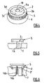
- the figure 3 schematically illustrates a mixture assembly, according to the invention.
- This assembly comprises a tank 1, a mixing device 14, inlet means 9 and means 10 for evacuating the fluids.
- At least two fluids intended to be mixed in the tank 1 are conveyed by the arrival means 9, pass through the tank 1 and are evacuated by the evacuation means 10.
- the means of arrival 9 and evacuation 10 comprise each a fluid passage pipe and a valve 12, 13 for regulating the flow of arrival and evacuation.
- the mixing assembly is equipped with means, such as a pump 11, for evacuating the inside of the tank 1.
- means such as a pump 11, for evacuating the inside of the tank 1.
- the depression prevailing inside the tank may extend between 0 and 0.99 bar.
- the mixing device according to the invention comprises a rotor 2 which rotates inside an annular ring 5.
- the rotor 2 cooperates with motor means 4 in order to be rotated and comprises mixing blades 3a, 3b, 3c, 3d arranged to suck the mixture axially and project it radially through the rotor 2.
- the rotor 2 is connected to the motor means 4 by a shaft 16 and comprises, for this purpose, a cylindrical bore 17 (see figures 7 and 8 ) for connecting the end of the shaft 16 to the rotor 2.
- the mixing device further comprises an annular ring 5 surrounding the rotor 2.
- the annular ring 5 may be fixed, and in this case will be called rotor, or mobile in rotation (not shown).
- the ring 5 has an upper axial orifice 18 allowing the mixture sucked in by the rotor 2 to pass.
- the annular ring 5 comprises, on its periphery, orifices 6 for the passage of the mixture radially projected by said rotor 2.
- the orifices radial 6 are slots parallel to each other and are separated by parts serving as an impact surface.
- the mixture projected by the rotor 2, through the openings 6, in the radial direction undergoes shear in this radial direction.
- the gap between the rotor 2 and the annular ring 5 is sufficiently small so as to obtain the desired shear stresses.
- the mixing assembly may comprise one or more turbines, not shown, arranged inside the vessel 1 and arranged to cause mixing , in the direction of the arrows f2, towards the axis of the rotor 2.
- the mixing device is embodied in the form of a motor unit, comprising the motor means 4, the shaft 16, the rotor 2, the annular ring 5 and a casing 18 for accommodating the shaft 16.
- the device comprises a duct 7 for supplying the particles into the tank 1.
- the supply duct 7 opens directly into the annular ring 5.
- Another end of the supply duct 7 is intended to be immersed in a particle reservoir so as to ensure the aspiration of the particles.
- the introduction of the particles inside the tank 1 is ensured by the depression prevailing inside the tank 1 and a valve 8 equipping the supply duct 7 allows to regulate the rate of introduction of particles into the tank 1.
- the supply duct 7 opens near the radial end of the blades 3a, 3b, 3c, 3d.
- the introduction of the particles is encouraged by the radial projection of the mixture during the rotation of the rotor 2.
- valve 8 is directly attached to the casing 18 of the engine block.
- the valve 8 used is, for example, a pneumatic valve with a valve 23.
- the annular ring 5 is supported by a circular plate 15.
- This plate 15 is intended to be inserted into a central cavity of the tank 1.
- the side wall of the plate 15 is equipped with a groove circular 19 and an O-ring housed in said circular groove 19. The seal ensures the tightness of the tank liquid and pressure.
- the shaft 16 passes through a central bore formed in the plate 15 and is guided in rotation by guide bearings 20, 21 supported by the housing 18.
- the housing 18 supports an O-ring 22 for sealing, with gas and liquids, the central bore of the plate 15.
- the plate 15 comprises a particle feed port connected to the conduit 7 for feeding the particles.
- the valve 23 of the valve 8 closes the passage between the supply duct and the supply port while in the open position, illustrated on the figure 7 the valve 23 of the valve 8 releases the passage space of the particles.
- the valve 8 may be equipped with sensors making it possible to detect the position of the valve 23.
- the engine block further comprises watertight fastening means to the tank 1, not shown, arranged between the rotor 2 and the supply duct 7.
- the plate 15 is for example secured to the tank 1 by welding , or using screws inserted through orifices formed in the plate 15 and cooperating with orifices formed in the vessel 1.
- the supply duct 7 passes through the fastening means.
- the tank 1 has only one opening for the passage of the supply duct 7 of the rotor 2 and the annular ring 5.
- the figure 8 illustrates a mixing device according to a second embodiment, comprising two coaxial rotors 2a, 2b for rotating in opposite directions.
- the engine block comprises an outer shaft 16b rotatably mounted on the housing 18 by means of bearings 24 and cooperating with the outer rotor 2b, and an inner shaft 16a coaxial with the outer shaft 16b, guided in rotation on the outer shaft 16b by means of bearings 25 and cooperating with the central rotor 2a.
- the two shafts 16a, 16b cooperate with motor means 4 so as to be driven in the opposite direction.
- the rotational speed of the shafts 16a, 16b is of the order of 3000 revolutions / minute.
- the tank 1 is kept under pressure by the pump 11.
- valve 8 is moved to the open position, so that the particles coming from the supply duct 7 are sucked via the inside of the annular ring of the stator 5, inside the tank 1. valve 8 is then moved to its closed position when the desired amount of particles has been introduced.
- the preparation is evacuated via the evacuation means 10.
- two immiscible substances are mixed in order to obtain an emulsion.
Landscapes
- Chemical & Material Sciences (AREA)
- Chemical Kinetics & Catalysis (AREA)
- Dispersion Chemistry (AREA)
- Mixers Of The Rotary Stirring Type (AREA)
- Accessories For Mixers (AREA)
Claims (15)
- Mischgruppe, die umfasst:- einen Behälter (1),- Mittel (11), um im Innern des Behälters das Vakuum herzustellen, und- eine Mischvorrichtung (14), die imstande ist, eine Turbulenzzone zu erzeugen und umfasst:- mindestens einen Rotor (2), der dazu bestimmt ist, mit Motormitteln (4) zusammenzuarbeiten, um rotierend angetrieben zu sein, und- einen ringförmigen Kranz (5), der den Rotor (2) umgibt und mindestens eine axiale Öffnung und radiale Öffnungen (6) für den Durchgang des Gemischs aufweist,- eine Zuführungsleitung (7) von Partikeln, die dazu bestimmt sind, in das Gemisch untergemischt zu sein, die an der Basis des Systems Rotor/ringförmiger Kranz in das Innere des ringförmigen Kranzes (5) mündet.
- Gruppe nach Anspruch 1, wobei die Mischvorrichtung (14) einen Motorblock umfasst, der Motormittel (4) und eine Welle (16) umfasst, die den Rotor (2) mit den Motormitteln (4) verbindet.
- Gruppe nach Anspruch 2, wobei der Motorblock mindestens einen Abschnitt der Zuführungsleitung (7) stützt.
- Gruppe nach einem der Ansprüche 2 oder 3, wobei die Zuführungsleitung (7) mit einem vom Motorblock gestützten Ventil (8) ausgestattet ist.
- Gruppe nach Anspruch 4, wobei das Ventil (8) ein Klappenventil (23) ist.
- Gruppe nach einem der Ansprüche 4 oder 5, wobei das Ventil (8) ein pneumatisches Ventil ist.
- Gruppe nach einem der Ansprüche 2 bis 6, wobei der Motorblock den Rotor (2) und den ringförmigen Kranz (5) umfasst.
- Gruppe nach einem der Ansprüche 2 bis 7, wobei der Motorblock Befestigungsmittel am Mischbehälter (1) umfasst.
- Gruppe nach Anspruch 8, wobei die Befestigungsmittel druckdicht sind.
- Gruppe nach einem der Ansprüche 8 oder 9, wobei die Zuführungsleitung (7) die Befestigungsmittel am Behälter (1) durchquert.
- Gruppe nach einem der Ansprüche 2 bis 10, wobei der Motorblock zwei koaxiale Rotoren (2a, 2b) aufweist.
- Gruppe nach einem der vorangehenden Ansprüche, wobei der Rotor (2) Mischschaufeln (3a, 3b, 3c, 3d) aufweist, die ausgebildet sind, um das Gemisch durch die axiale Öffnung des ringförmigen Kranzes (5) anzusaugen und es radial durch radiale Öffnungen (6) des ringförmigen Kranzes (5) zu projizieren.
- Gruppe nach Anspruch 12, wobei die Zuführungsleitung (7) in der Nähe des radialen Endes der Mischschaufeln (3a, 3b, 3c, 3d) des Rotors (2) mündet.
- Verfahren zur Herstellung eines Präparats, das einen Mischschritt mit Hilfe einer Gruppe nach einem der vorangehenden Ansprüche umfasst, das ferner einen Schritt der Einführung durch Ansaugen von Partikeln in den in Unterdruck gehaltenen Behälter (1) über den ringförmigen Kranz (5) an der Basis des Systems Rotor/ringförmiger Kranz umfasst, um die Partikel in das Gemisch unterzumischen.
- Verfahren nach Anspruch 14, wobei mindestens zwei nicht mischbare Substanzen gemischt werden, um eine Emulsion herzustellen.
Applications Claiming Priority (2)
| Application Number | Priority Date | Filing Date | Title |
|---|---|---|---|
| FR0801761A FR2929133B1 (fr) | 2008-03-31 | 2008-03-31 | Dispositif de melange comprenant un conduit d'amenee de particules debouchant dans la zone de turbulences |
| PCT/FR2009/000151 WO2009122021A1 (fr) | 2008-03-31 | 2009-02-11 | Ensemble de melange, et procede de fabrication d'une reparation utilisant ledit ensemble |
Publications (2)
| Publication Number | Publication Date |
|---|---|
| EP2265362A1 EP2265362A1 (de) | 2010-12-29 |
| EP2265362B1 true EP2265362B1 (de) | 2012-12-26 |
Family
ID=39926541
Family Applications (1)
| Application Number | Title | Priority Date | Filing Date |
|---|---|---|---|
| EP09726774A Active EP2265362B1 (de) | 2008-03-31 | 2009-02-11 | Mischvorrichtung und verfahren zur herstellung eines präparats mit dieser mischvorrichtung |
Country Status (6)
| Country | Link |
|---|---|
| US (1) | US8960993B2 (de) |
| EP (1) | EP2265362B1 (de) |
| CA (1) | CA2717460A1 (de) |
| ES (1) | ES2401411T3 (de) |
| FR (1) | FR2929133B1 (de) |
| WO (1) | WO2009122021A1 (de) |
Families Citing this family (22)
| Publication number | Priority date | Publication date | Assignee | Title |
|---|---|---|---|---|
| FR2929133B1 (fr) * | 2008-03-31 | 2010-12-10 | Vmi | Dispositif de melange comprenant un conduit d'amenee de particules debouchant dans la zone de turbulences |
| ITMI20091797A1 (it) * | 2009-10-19 | 2011-04-20 | Giordano Colombo | Apparecchiatura di reazione ed emulsificazione, particolarmente per emulsionare acqua e combustibile diesel e metodo di emulsificazione utilizzante tale apparecchiatura |
| WO2012023217A1 (ja) * | 2010-08-19 | 2012-02-23 | 株式会社明治 | 微粒化装置及びその性能評価方法とスケールアップ方法 |
| WO2012023608A1 (ja) * | 2010-08-19 | 2012-02-23 | 株式会社明治 | 微粒化装置の性能評価方法及びスケールアップ方法 |
| US9358509B2 (en) * | 2010-08-19 | 2016-06-07 | Meiji Co., Ltd. | Particle size breakup apparatus having a rotor and a stator |
| FI123888B (fi) * | 2010-11-26 | 2013-12-13 | Outotec Oyj | Pumppu |
| FR2970879B1 (fr) | 2011-01-31 | 2013-02-15 | Vmi | Dispositif de melange |
| TWI604885B (zh) * | 2011-08-19 | 2017-11-11 | 明治股份有限公司 | Microprocessing equipment |
| KR20150100629A (ko) | 2012-12-25 | 2015-09-02 | 엠. 테크닉 가부시키가이샤 | 교반 처리 장치 및 처리 방법 |
| US12102970B2 (en) | 2014-02-27 | 2024-10-01 | Schlumberger Technology Corporation | Integrated process delivery at wellsite |
| US11819810B2 (en) | 2014-02-27 | 2023-11-21 | Schlumberger Technology Corporation | Mixing apparatus with flush line and method |
| US12576556B2 (en) | 2014-02-27 | 2026-03-17 | Schlumberger Technology Corporation | Hydration systems and methods |
| EP3218093B1 (de) | 2014-11-10 | 2018-12-26 | EME Finance Ltd | Vorrichtung zum mischen von wasser und dieselöl, vorrichtung und verfahren zur herstellung einer wasser/dieselöl-mikroemulsion |
| IT201600132801A1 (it) | 2016-12-30 | 2018-06-30 | Eme International Ltd | Apparato e processo per produrre liquido derivante da biomassa, biocarburante e biomateriale |
| WO2020120504A1 (en) * | 2018-12-13 | 2020-06-18 | Tetra Laval Holdings & Finance S.A. | A mixer for a food product |
| US11304565B2 (en) | 2019-03-08 | 2022-04-19 | Sharkninja Operating Llc | Vacuum food processing system |
| US11771265B2 (en) | 2019-03-08 | 2023-10-03 | Sharkninja Operating Llc | Vacuum food processing system |
| JP2022516278A (ja) | 2019-03-08 | 2022-02-25 | シャークニンジャ オペレーティング エルエルシー | 真空食品加工システム |
| USD924007S1 (en) | 2019-06-06 | 2021-07-06 | Sharkninja Operating Llc | Strainer blender accessory |
| USD927256S1 (en) | 2019-06-06 | 2021-08-10 | Sharkninja Operating Llc | Blender |
| USD940500S1 (en) | 2019-06-06 | 2022-01-11 | Sharkninja Operating Llc | Lid |
| USD925270S1 (en) | 2019-06-06 | 2021-07-20 | Sharkninja Operating Llc | Blender |
Citations (2)
| Publication number | Priority date | Publication date | Assignee | Title |
|---|---|---|---|---|
| US20020110533A1 (en) * | 1998-07-02 | 2002-08-15 | Rainer Huff | Method for producing aqueous emulsions or suspensions |
| US6866411B1 (en) * | 2000-01-31 | 2005-03-15 | Tetra Laval Holdings & Finance S.A. | Mixing method and apparatus |
Family Cites Families (12)
| Publication number | Priority date | Publication date | Assignee | Title |
|---|---|---|---|---|
| US1496641A (en) * | 1923-09-21 | 1924-06-03 | Guy C Hurrell | Mixing, incorporating, and disintegrating machine |
| CH271109A (fr) * | 1945-11-27 | 1950-10-15 | Separation L Emulsion Et Le Me | Appareil pour mélanger des substances fluides à l'intérieur d'une cuve. |
| ES264687A1 (es) * | 1960-02-17 | 1961-07-01 | Algemene Kunstzijde Unie Nv | Un aparato mezclador |
| DK174688B1 (da) * | 2001-06-12 | 2003-09-15 | Scanima As | Homogeniseringsmaskine til behandling af produkter, der skal homogeniseres, især næringsmidler, hvori der indgår mejeriprodukter |
| DE8006977U1 (de) * | 1980-03-14 | 1980-07-03 | Haagen & Rinau Gmbh & Co Kg, 2800 Bremen | Vorrichtung zum mischen und homogenisieren wenigstens zweier medien |
| DE29606962U1 (de) * | 1996-04-17 | 1997-08-21 | Haagen & Rinau Mischtechnik GmbH, 28357 Bremen | Vorrichtung zum Homogenisieren und/oder Dispergieren eines fließfähigen Guts |
| DE50011334D1 (de) * | 2000-05-19 | 2006-02-23 | Vakumix Ruehr Und Homogenisier | Homogenisator zur Herstellung fliessfähiger Stoffe |
| FR2835762B1 (fr) * | 2002-02-08 | 2005-02-18 | Vmi | Dispositif de melange et d'homogeneisation destine a la production d'emulsions |
| DE10320739B3 (de) * | 2003-05-09 | 2004-10-21 | Ika - Werke Gmbh & Co. Kg | Vorrichtung zum Dispergieren und/oder Homogenisieren |
| US7261545B2 (en) * | 2003-11-18 | 2007-08-28 | Chip Investments, Llc | Powder preheating |
| FR2929133B1 (fr) * | 2008-03-31 | 2010-12-10 | Vmi | Dispositif de melange comprenant un conduit d'amenee de particules debouchant dans la zone de turbulences |
| FR2970879B1 (fr) * | 2011-01-31 | 2013-02-15 | Vmi | Dispositif de melange |
-
2008
- 2008-03-31 FR FR0801761A patent/FR2929133B1/fr not_active Expired - Fee Related
-
2009
- 2009-02-11 WO PCT/FR2009/000151 patent/WO2009122021A1/fr not_active Ceased
- 2009-02-11 ES ES09726774T patent/ES2401411T3/es active Active
- 2009-02-11 EP EP09726774A patent/EP2265362B1/de active Active
- 2009-02-11 US US12/935,629 patent/US8960993B2/en active Active
- 2009-02-11 CA CA2717460A patent/CA2717460A1/fr not_active Abandoned
Patent Citations (2)
| Publication number | Priority date | Publication date | Assignee | Title |
|---|---|---|---|---|
| US20020110533A1 (en) * | 1998-07-02 | 2002-08-15 | Rainer Huff | Method for producing aqueous emulsions or suspensions |
| US6866411B1 (en) * | 2000-01-31 | 2005-03-15 | Tetra Laval Holdings & Finance S.A. | Mixing method and apparatus |
Also Published As
| Publication number | Publication date |
|---|---|
| US8960993B2 (en) | 2015-02-24 |
| FR2929133B1 (fr) | 2010-12-10 |
| WO2009122021A1 (fr) | 2009-10-08 |
| EP2265362A1 (de) | 2010-12-29 |
| US20110026358A1 (en) | 2011-02-03 |
| FR2929133A1 (fr) | 2009-10-02 |
| CA2717460A1 (fr) | 2009-10-08 |
| ES2401411T3 (es) | 2013-04-19 |
Similar Documents
| Publication | Publication Date | Title |
|---|---|---|
| FR2929133A1 (fr) | Dispositif de melange comprenant un conduit d'amenee de particules debouchant dans la zone de turbulences | |
| CA2825640C (fr) | Dispositif de melange | |
| JPH0327258B2 (de) | ||
| FR2486820A1 (fr) | Induit de moteur electrique utilise directement en organe melangeur et/ou propulseur pour fluides | |
| EP0687197B1 (de) | Apparat zum einführen und zerstreuen von luft oder einem anderen gas in eine flüssigkeit | |
| EP2798223A1 (de) | Adapter für vakuumpumpen und zugehörige pumpvorrichtung | |
| CA2947249A1 (fr) | Assemblage pour turbomachine d'aeronef et son procede de montage | |
| EP0654297B1 (de) | Anlage und Vorrichtung zum Mischen visköser Produkte und/oder Flüssigkeiten und Anwendung einer solchen Vorrichtung | |
| EP3721093A1 (de) | Pumpe mit einem axialen ausgleichssystem | |
| FR2624408A1 (fr) | Dispositif de nettoyage de l'interieur d'un recipient avec un jet de liquide | |
| EP1990543A1 (de) | Trockenvakuumpumpe | |
| FR2466271A1 (fr) | Dispositif pour melanger deux fluides, notamment de l'air ozone avec de l'eau | |
| FR3049655A1 (fr) | Carter ameliore de turbopompe d'alimentation en ergol pour moteur-fusee | |
| FR3099220A1 (fr) | Réducteur de vitesse à train épicycloïdal pour une turbomachine | |
| CN107921382B (zh) | 用于使至少一种物质在流体中分散的装置和方法 | |
| WO2012098329A1 (fr) | Dispositif, installation et procede pour melanger des substances sous forme liquide et/ou pulverulente | |
| EP1614352B1 (de) | Kontinuierliche Mischvorrichtung für Teigmittel mit einem Zentrifugalmischwerkzeug und einem Seitenauslass, Verfahren und Anlage | |
| WO2020260796A1 (fr) | Support de palier de sortie de turbomachine | |
| FR3146075A1 (fr) | Dispositif de pulverisation centrifuge de liquide avec etancheite dynamique sans friction | |
| TW202430279A (zh) | 混合排出裝置 | |
| FR2944979A1 (fr) | Dispositif de melange de poudre avec un liquide comprenant un tube de dispersion | |
| BE559622A (de) | ||
| EP0456798B1 (de) | Vorrichtung zur evakuierung eines rezipienten | |
| FR2868336A1 (fr) | Dispositif melangeur a rotor et stator | |
| FR2626193A1 (fr) | Procede et dispositif pour l'homogeneisation d'un melange de gaz dans un recipient |
Legal Events
| Date | Code | Title | Description |
|---|---|---|---|
| PUAI | Public reference made under article 153(3) epc to a published international application that has entered the european phase |
Free format text: ORIGINAL CODE: 0009012 |
|
| 17P | Request for examination filed |
Effective date: 20100827 |
|
| AK | Designated contracting states |
Kind code of ref document: A1 Designated state(s): AT BE BG CH CY CZ DE DK EE ES FI FR GB GR HR HU IE IS IT LI LT LU LV MC MK MT NL NO PL PT RO SE SI SK TR |
|
| AX | Request for extension of the european patent |
Extension state: AL BA RS |
|
| 17Q | First examination report despatched |
Effective date: 20110419 |
|
| DAX | Request for extension of the european patent (deleted) | ||
| GRAP | Despatch of communication of intention to grant a patent |
Free format text: ORIGINAL CODE: EPIDOSNIGR1 |
|
| RIC1 | Information provided on ipc code assigned before grant |
Ipc: B01F 15/02 20060101ALI20120906BHEP Ipc: B01F 3/08 20060101ALI20120906BHEP Ipc: B01F 7/16 20060101AFI20120906BHEP Ipc: B01F 3/12 20060101ALI20120906BHEP |
|
| GRAS | Grant fee paid |
Free format text: ORIGINAL CODE: EPIDOSNIGR3 |
|
| GRAA | (expected) grant |
Free format text: ORIGINAL CODE: 0009210 |
|
| AK | Designated contracting states |
Kind code of ref document: B1 Designated state(s): AT BE BG CH CY CZ DE DK EE ES FI FR GB GR HR HU IE IS IT LI LT LU LV MC MK MT NL NO PL PT RO SE SI SK TR |
|
| REG | Reference to a national code |
Ref country code: GB Ref legal event code: FG4D Free format text: NOT ENGLISH |
|
| REG | Reference to a national code |
Ref country code: CH Ref legal event code: EP |
|
| REG | Reference to a national code |
Ref country code: AT Ref legal event code: REF Ref document number: 590140 Country of ref document: AT Kind code of ref document: T Effective date: 20130115 |
|
| REG | Reference to a national code |
Ref country code: DE Ref legal event code: R096 Ref document number: 602009012249 Country of ref document: DE Effective date: 20130307 |
|
| REG | Reference to a national code |
Ref country code: ES Ref legal event code: FG2A Ref document number: 2401411 Country of ref document: ES Kind code of ref document: T3 Effective date: 20130419 |
|
| PG25 | Lapsed in a contracting state [announced via postgrant information from national office to epo] |
Ref country code: SE Free format text: LAPSE BECAUSE OF FAILURE TO SUBMIT A TRANSLATION OF THE DESCRIPTION OR TO PAY THE FEE WITHIN THE PRESCRIBED TIME-LIMIT Effective date: 20121226 Ref country code: NO Free format text: LAPSE BECAUSE OF FAILURE TO SUBMIT A TRANSLATION OF THE DESCRIPTION OR TO PAY THE FEE WITHIN THE PRESCRIBED TIME-LIMIT Effective date: 20130326 Ref country code: HR Free format text: LAPSE BECAUSE OF FAILURE TO SUBMIT A TRANSLATION OF THE DESCRIPTION OR TO PAY THE FEE WITHIN THE PRESCRIBED TIME-LIMIT Effective date: 20121226 Ref country code: LT Free format text: LAPSE BECAUSE OF FAILURE TO SUBMIT A TRANSLATION OF THE DESCRIPTION OR TO PAY THE FEE WITHIN THE PRESCRIBED TIME-LIMIT Effective date: 20121226 Ref country code: FI Free format text: LAPSE BECAUSE OF FAILURE TO SUBMIT A TRANSLATION OF THE DESCRIPTION OR TO PAY THE FEE WITHIN THE PRESCRIBED TIME-LIMIT Effective date: 20121226 |
|
| REG | Reference to a national code |
Ref country code: AT Ref legal event code: MK05 Ref document number: 590140 Country of ref document: AT Kind code of ref document: T Effective date: 20121226 |
|
| REG | Reference to a national code |
Ref country code: LT Ref legal event code: MG4D |
|
| REG | Reference to a national code |
Ref country code: NL Ref legal event code: VDEP Effective date: 20121226 |
|
| PG25 | Lapsed in a contracting state [announced via postgrant information from national office to epo] |
Ref country code: LV Free format text: LAPSE BECAUSE OF FAILURE TO SUBMIT A TRANSLATION OF THE DESCRIPTION OR TO PAY THE FEE WITHIN THE PRESCRIBED TIME-LIMIT Effective date: 20121226 Ref country code: GR Free format text: LAPSE BECAUSE OF FAILURE TO SUBMIT A TRANSLATION OF THE DESCRIPTION OR TO PAY THE FEE WITHIN THE PRESCRIBED TIME-LIMIT Effective date: 20130327 Ref country code: SI Free format text: LAPSE BECAUSE OF FAILURE TO SUBMIT A TRANSLATION OF THE DESCRIPTION OR TO PAY THE FEE WITHIN THE PRESCRIBED TIME-LIMIT Effective date: 20121226 |
|
| PG25 | Lapsed in a contracting state [announced via postgrant information from national office to epo] |
Ref country code: BG Free format text: LAPSE BECAUSE OF FAILURE TO SUBMIT A TRANSLATION OF THE DESCRIPTION OR TO PAY THE FEE WITHIN THE PRESCRIBED TIME-LIMIT Effective date: 20130326 Ref country code: SK Free format text: LAPSE BECAUSE OF FAILURE TO SUBMIT A TRANSLATION OF THE DESCRIPTION OR TO PAY THE FEE WITHIN THE PRESCRIBED TIME-LIMIT Effective date: 20121226 Ref country code: AT Free format text: LAPSE BECAUSE OF FAILURE TO SUBMIT A TRANSLATION OF THE DESCRIPTION OR TO PAY THE FEE WITHIN THE PRESCRIBED TIME-LIMIT Effective date: 20121226 Ref country code: IS Free format text: LAPSE BECAUSE OF FAILURE TO SUBMIT A TRANSLATION OF THE DESCRIPTION OR TO PAY THE FEE WITHIN THE PRESCRIBED TIME-LIMIT Effective date: 20130426 Ref country code: CZ Free format text: LAPSE BECAUSE OF FAILURE TO SUBMIT A TRANSLATION OF THE DESCRIPTION OR TO PAY THE FEE WITHIN THE PRESCRIBED TIME-LIMIT Effective date: 20121226 Ref country code: EE Free format text: LAPSE BECAUSE OF FAILURE TO SUBMIT A TRANSLATION OF THE DESCRIPTION OR TO PAY THE FEE WITHIN THE PRESCRIBED TIME-LIMIT Effective date: 20121226 |
|
| PG25 | Lapsed in a contracting state [announced via postgrant information from national office to epo] |
Ref country code: NL Free format text: LAPSE BECAUSE OF FAILURE TO SUBMIT A TRANSLATION OF THE DESCRIPTION OR TO PAY THE FEE WITHIN THE PRESCRIBED TIME-LIMIT Effective date: 20121226 Ref country code: PL Free format text: LAPSE BECAUSE OF FAILURE TO SUBMIT A TRANSLATION OF THE DESCRIPTION OR TO PAY THE FEE WITHIN THE PRESCRIBED TIME-LIMIT Effective date: 20121226 Ref country code: RO Free format text: LAPSE BECAUSE OF FAILURE TO SUBMIT A TRANSLATION OF THE DESCRIPTION OR TO PAY THE FEE WITHIN THE PRESCRIBED TIME-LIMIT Effective date: 20121226 Ref country code: PT Free format text: LAPSE BECAUSE OF FAILURE TO SUBMIT A TRANSLATION OF THE DESCRIPTION OR TO PAY THE FEE WITHIN THE PRESCRIBED TIME-LIMIT Effective date: 20130426 |
|
| BERE | Be: lapsed |
Owner name: VMI Effective date: 20130228 |
|
| PG25 | Lapsed in a contracting state [announced via postgrant information from national office to epo] |
Ref country code: MC Free format text: LAPSE BECAUSE OF NON-PAYMENT OF DUE FEES Effective date: 20130228 |
|
| REG | Reference to a national code |
Ref country code: CH Ref legal event code: PL |
|
| PG25 | Lapsed in a contracting state [announced via postgrant information from national office to epo] |
Ref country code: DK Free format text: LAPSE BECAUSE OF FAILURE TO SUBMIT A TRANSLATION OF THE DESCRIPTION OR TO PAY THE FEE WITHIN THE PRESCRIBED TIME-LIMIT Effective date: 20121226 Ref country code: CH Free format text: LAPSE BECAUSE OF NON-PAYMENT OF DUE FEES Effective date: 20130228 Ref country code: LI Free format text: LAPSE BECAUSE OF NON-PAYMENT OF DUE FEES Effective date: 20130228 |
|
| PLBE | No opposition filed within time limit |
Free format text: ORIGINAL CODE: 0009261 |
|
| STAA | Information on the status of an ep patent application or granted ep patent |
Free format text: STATUS: NO OPPOSITION FILED WITHIN TIME LIMIT |
|
| PG25 | Lapsed in a contracting state [announced via postgrant information from national office to epo] |
Ref country code: CY Free format text: LAPSE BECAUSE OF FAILURE TO SUBMIT A TRANSLATION OF THE DESCRIPTION OR TO PAY THE FEE WITHIN THE PRESCRIBED TIME-LIMIT Effective date: 20121226 |
|
| 26N | No opposition filed |
Effective date: 20130927 |
|
| REG | Reference to a national code |
Ref country code: IE Ref legal event code: MM4A |
|
| REG | Reference to a national code |
Ref country code: DE Ref legal event code: R097 Ref document number: 602009012249 Country of ref document: DE Effective date: 20130927 |
|
| PG25 | Lapsed in a contracting state [announced via postgrant information from national office to epo] |
Ref country code: IE Free format text: LAPSE BECAUSE OF NON-PAYMENT OF DUE FEES Effective date: 20130211 Ref country code: BE Free format text: LAPSE BECAUSE OF NON-PAYMENT OF DUE FEES Effective date: 20130228 |
|
| PG25 | Lapsed in a contracting state [announced via postgrant information from national office to epo] |
Ref country code: MT Free format text: LAPSE BECAUSE OF FAILURE TO SUBMIT A TRANSLATION OF THE DESCRIPTION OR TO PAY THE FEE WITHIN THE PRESCRIBED TIME-LIMIT Effective date: 20121226 |
|
| PG25 | Lapsed in a contracting state [announced via postgrant information from national office to epo] |
Ref country code: TR Free format text: LAPSE BECAUSE OF FAILURE TO SUBMIT A TRANSLATION OF THE DESCRIPTION OR TO PAY THE FEE WITHIN THE PRESCRIBED TIME-LIMIT Effective date: 20121226 |
|
| PG25 | Lapsed in a contracting state [announced via postgrant information from national office to epo] |
Ref country code: HU Free format text: LAPSE BECAUSE OF FAILURE TO SUBMIT A TRANSLATION OF THE DESCRIPTION OR TO PAY THE FEE WITHIN THE PRESCRIBED TIME-LIMIT; INVALID AB INITIO Effective date: 20090211 Ref country code: MK Free format text: LAPSE BECAUSE OF FAILURE TO SUBMIT A TRANSLATION OF THE DESCRIPTION OR TO PAY THE FEE WITHIN THE PRESCRIBED TIME-LIMIT Effective date: 20121226 Ref country code: LU Free format text: LAPSE BECAUSE OF NON-PAYMENT OF DUE FEES Effective date: 20130211 |
|
| REG | Reference to a national code |
Ref country code: FR Ref legal event code: PLFP Year of fee payment: 8 |
|
| REG | Reference to a national code |
Ref country code: FR Ref legal event code: PLFP Year of fee payment: 9 |
|
| REG | Reference to a national code |
Ref country code: FR Ref legal event code: PLFP Year of fee payment: 10 |
|
| REG | Reference to a national code |
Ref country code: DE Ref legal event code: R119 Ref document number: 602009012249 Country of ref document: DE |
|
| PG25 | Lapsed in a contracting state [announced via postgrant information from national office to epo] |
Ref country code: DE Free format text: LAPSE BECAUSE OF NON-PAYMENT OF DUE FEES Effective date: 20200901 |
|
| PGFP | Annual fee paid to national office [announced via postgrant information from national office to epo] |
Ref country code: GB Payment date: 20251230 Year of fee payment: 18 |
|
| PGFP | Annual fee paid to national office [announced via postgrant information from national office to epo] |
Ref country code: FR Payment date: 20251124 Year of fee payment: 18 |
|
| PGFP | Annual fee paid to national office [announced via postgrant information from national office to epo] |
Ref country code: IT Payment date: 20260210 Year of fee payment: 18 |
|
| PGFP | Annual fee paid to national office [announced via postgrant information from national office to epo] |
Ref country code: ES Payment date: 20260511 Year of fee payment: 18 |