EP2265784B1 - Verstellvorrichtung für möbel - Google Patents
Verstellvorrichtung für möbel Download PDFInfo
- Publication number
- EP2265784B1 EP2265784B1 EP09732125.1A EP09732125A EP2265784B1 EP 2265784 B1 EP2265784 B1 EP 2265784B1 EP 09732125 A EP09732125 A EP 09732125A EP 2265784 B1 EP2265784 B1 EP 2265784B1
- Authority
- EP
- European Patent Office
- Prior art keywords
- housing
- adjusting apparatus
- rotary element
- adjusting
- cut
- Prior art date
- Legal status (The legal status is an assumption and is not a legal conclusion. Google has not performed a legal analysis and makes no representation as to the accuracy of the status listed.)
- Active
Links
Images


Classifications
-
- A—HUMAN NECESSITIES
- A47—FURNITURE; DOMESTIC ARTICLES OR APPLIANCES; COFFEE MILLS; SPICE MILLS; SUCTION CLEANERS IN GENERAL
- A47B—TABLES; DESKS; OFFICE FURNITURE; CABINETS; DRAWERS; GENERAL DETAILS OF FURNITURE
- A47B88/00—Drawers for tables, cabinets or like furniture; Guides for drawers
- A47B88/90—Constructional details of drawers
- A47B88/944—Drawers characterised by the front panel
- A47B88/95—Drawers characterised by the front panel characterised by connection means for the front panel
- A47B88/956—Drawers characterised by the front panel characterised by connection means for the front panel for enabling adjustment of the front panel
-
- E—FIXED CONSTRUCTIONS
- E05—LOCKS; KEYS; WINDOW OR DOOR FITTINGS; SAFES
- E05D—HINGES OR SUSPENSION DEVICES FOR DOORS, WINDOWS OR WINGS
- E05D7/00—Hinges or pivots of special construction
- E05D7/04—Hinges adjustable relative to the wing or the frame
- E05D7/0407—Hinges adjustable relative to the wing or the frame the hinges having two or more pins and being specially adapted for cabinets or furniture
-
- E—FIXED CONSTRUCTIONS
- E05—LOCKS; KEYS; WINDOW OR DOOR FITTINGS; SAFES
- E05D—HINGES OR SUSPENSION DEVICES FOR DOORS, WINDOWS OR WINGS
- E05D7/00—Hinges or pivots of special construction
- E05D7/04—Hinges adjustable relative to the wing or the frame
- E05D7/0415—Hinges adjustable relative to the wing or the frame with adjusting drive means
-
- A—HUMAN NECESSITIES
- A47—FURNITURE; DOMESTIC ARTICLES OR APPLIANCES; COFFEE MILLS; SPICE MILLS; SUCTION CLEANERS IN GENERAL
- A47B—TABLES; DESKS; OFFICE FURNITURE; CABINETS; DRAWERS; GENERAL DETAILS OF FURNITURE
- A47B88/00—Drawers for tables, cabinets or like furniture; Guides for drawers
- A47B88/90—Constructional details of drawers
- A47B88/919—Accessories or additional elements for drawers, e.g. drawer lighting
- A47B88/931—Rails or rods mounted above the drawer walls, e.g. for stabilisation of the drawer or for suspension of the content
- A47B88/938—Means for connecting rails or rods to drawers
- A47B2088/939—Means for connecting rails or rods to drawers to the front panel of a drawer
-
- E—FIXED CONSTRUCTIONS
- E05—LOCKS; KEYS; WINDOW OR DOOR FITTINGS; SAFES
- E05Y—INDEXING SCHEME ASSOCIATED WITH SUBCLASSES E05D AND E05F, RELATING TO CONSTRUCTION ELEMENTS, ELECTRIC CONTROL, POWER SUPPLY, POWER SIGNAL OR TRANSMISSION, USER INTERFACES, MOUNTING OR COUPLING, DETAILS, ACCESSORIES, AUXILIARY OPERATIONS NOT OTHERWISE PROVIDED FOR, APPLICATION THEREOF
- E05Y2900/00—Application of doors, windows, wings or fittings thereof
- E05Y2900/20—Application of doors, windows, wings or fittings thereof for furniture, e.g. cabinets
Definitions
- the present invention relates to a drawer with an adjusting device with a housing and a displaceably mounted thereon, in which a recess and a rotary member is arranged, which shifts the surrounding housing relative to the part when rotating.
- a drawer is known in which a base plate is fixed to a side plate with an eccentric disc.
- the rotatably mounted eccentric can act on an elbow, which is fixed to the front panel.
- the position of the front panel can be changed relative to the side wall, in particular to align the front panel to a front of a piece of furniture.
- Such adjustment is comparatively expensive to install, since the base plate and the elbow must be fixed to the side wall or front panel and then a corresponding adjustment must be made to align.
- An eccentric adjustment has the disadvantage that the adjustment path changes strongly and non-linearly relative to the angle of rotation, which leads to an uneven adjustment with uniform rotation.
- the effective lever arm changes and the maximum displacement is limited.
- the EP 1 203 861 discloses a furniture hinge with an adjustment, which has an eccentric disc.
- the rotary element has two control disks which each act on a contact surface on the recess.
- the contact surfaces are in Adjusting arranged on opposite sides of the recess, so that the maximum adjustment is very large, since a control disk is responsible for a displacement in one direction only.
- Each control disc acts only on a contact surface on the recess and on the opposite side, the respective control disc is spaced from a side wall disposed on the recess.
- the control discs are formed so that the angle of rotation and the sliding path are substantially proportional over the entire displacement.
- the geometry of the control disk can be chosen so that an angle change during rotation of the rotary member provides for a proportional displacement
- the rotary member for moving the housing over a rotation angle of more than 180 °, preferably more than 210 ° rotatable It is also possible to realize angles of rotation of more than 240 °, for example up to almost 360 °, so that a large angular range can be used for the displacement movement.
- the rotary member has an axis of rotation, wherein the effective lever arm for adjusting the housing is substantially constant.
- the control discs can each have an outer contact surface in the form of an involute, which extends around a base circle. As a result, the effective lever arm is kept constant, so that the forces remain approximately the same when adjusting.
- the two control discs can be formed symmetrically in a basic position to a central plane perpendicular to the adjustment.
- the recess for a compact design is arranged on the displaceably mounted part.
- the rotary member is rotatably supported by at least one pin on the housing.
- the housing may have a receptacle for inserting an end portion of the displaceably mounted part, so that the end portion is not visible from the outside.
- the recess is formed on the housing and the rotary member is rotatably supported via at least one pin on the displaceably mounted part, so that in the part only a circular opening must be provided as a bearing bush.
- the adjustment is designed as a multi-part rail, which is adjustable for adjusting the inclination of the front panel in length and at least two slidably guided together parts. This allows the adjustment of the front panel done in a simple manner in which only the length of the railing is adjusted accordingly. This can be used in particular in drawers, in which the change in length of the railing leads to a different position of the front panel in the upper area spaced from a floor. The adjustment is then simple with just a few components.
- the housing engages around a rod-shaped part, which is slidably received in the housing. This allows a stable linear guide in the adjustment, with a support in different directions is given perpendicular to the adjustment.
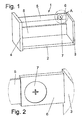
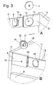
- a drawer 1 comprises a bottom 2, which is connected on one side to a front panel 3 and on the opposite side to a rear wall 4. Between the front panel 3 and the rear wall 4, a rail is mounted, which forms an adjusting device and a rod-shaped part 5 and a sleeve-shaped housing 6 has. On the housing 6, a rotary member 7 is provided for adjusting the length of the railing. Below the rail a side wall 8 between the rear wall 4 and front panel 3 is mounted on the bottom 2. By changing the length of the rail, the inclination of the front panel 3 can be changed.
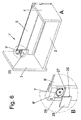
- the rod-shaped part 5 has a rectangular cross-section and is inserted into a corresponding opening on the sleeve-shaped housing 6 and can be moved in this.
- a rotary element 7 is provided, which engages in a recess 9 on the rod-shaped part 5.
- the rod-shaped part 5 is designed as a hollow profile, so that two adjacent side walls 10 and 11 are provided, which form in the region of the recess 9 contact surfaces 21 and 20.
- a small circular opening 13 is provided on the housing, wherein a larger circular opening 12 and on the opposite wall of the housing 6, a small circular opening 13 is provided.
- the small opening 13 serves to receive a pin 14 of the rotary element 7, which forms an axis of rotation.
- the large opening 12 forms a contact surface for a disk 17 of the rotary element 7, so that it is rotatably mounted on the housing 6.
- the rotary member 7 has a first control disk 15 and a second control disk 16, wherein the control disk 15 on the wall 11 and the control disk 16 on the wall 10 of the recess 9 rests uniformly.
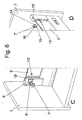
- the rotary element 7 is shown in the mounted position.
- the control disk 15 rests on the left side of the recess 9 on a contact surface 20, while the control disk 16 rests on the right side of the recess 9 on a contact surface 21 on the wall 10.
- Characterized the length of the rail is optionally shortened or extended when turning the rotary member 7 by means of a tool, wherein the control disk 15 for movement of the housing 6 to the right and the control disk 16 for movement of the housing 6 to the left provides, depending on which direction the rotating element 7 is rotated.
- FIG. 5A the rotary member 7 is shown in a position in which the control disk 15 rests against a line-shaped contact surface 20 on the wall 11 of the rod-shaped part 5 and on the opposite side a contact surface 21 is also formed linearly, between the control disk 16 and the wall 10 on the rod-shaped part 5.
- the control discs 15 and 16 are formed symmetrically to a central plane which extends perpendicularly through the axis of rotation of the rotary member 7. Further, the control discs 15 and 16 with their outer circumference as involutes. formed, which act on two opposite parallel contact surfaces 20, 21 of the recess 9 and thus provide a linear adjustment of the rail.
- the two control discs 15,16 are formed so that the contact surfaces of the control discs always bear against the contact surfaces of the recess of the rod-shaped part or at all angles of rotation, or are always in engagement with the contact surfaces of the recess.
- FIG. 5B is the rotary member 7 is rotated counterclockwise, the control disk 15 is always applied to the contact surface 20, however, the housing 6 is slightly shifted to the right. If the rotary element 7 is further rotated, the in FIG. 5C shown reached position in which the housing 6 a little further was moved to the right and the rod-shaped part 5 was pushed out of the housing 6. This extends the railing.
- FIG. 5D is shown a position in which the rotary member 7, starting from the position in FIG. 5A was turned clockwise to shorten the railing.
- the control disk 16 presses against the linear contact surface 21 and presses the housing 6 to the left.
- a stop 23 is formed, which abuts against a stop surface 22 on the recess 9.
- the maximum rotational travel of the rotary element 7 is limited.
- the rotation of the rotary member 7 is also limited by a stop on the control disk 16 in the opposite direction.
- the rod-shaped part 5 and the housing 6 may be made of plastic and / or metal and are guided substantially in a form-fitting manner to each other.
- the rotary member 7 may be formed one or more parts and is also made of plastic or metal. The rotary member 7 lies on opposite sides substantially form-fitting manner in the recess 9, so that a precise adjustment is possible.
- the rod-shaped part 5 is designed here as a hollow profile. Of course, it is also possible to provide a solid profile, wherein the recess 9 can then be formed correspondingly stepped.
- the rod-shaped part 5 and the receptacle in the housing 6 may also have a different contour than the rectangular cross-section.
- the rail 5 may also have a circular, oval or other cross-sectional shape.
- the housing 6 and the rod-shaped part 5 can be glued to the front panel 3 and the rear wall 4, screwed or mounted via other fastening means. In this case, the housing 6 may optionally be fixed to the front panel 3 or the rear wall 4.
- FIGS. 6A to 6D is a further embodiment of an adjusting device on a drawer 1 'shown.
- the adjusting device is arranged between a front panel 3 and a rear wall 4.
- a housing 6 ' is fixed, on which a plate-shaped part 5' is slidably mounted.
- a rotary element 7 ' is provided.
- the rotary member 7 ' has, as in the previous embodiment, a first control disk 15 and a second control disk 16, wherein the control disk 15 on a first wall 11 and the control disk 16 on a second wall 10 of the recess 9' is applied, as shown in the Figures 4B and 5A to 5D is shown, wherein the recess 9 'is not formed on the displaceable part 5' but on the housing 6 '.
- the rotary member 7 'further comprises a protruding pin 14 which is rotatably mounted in a circular opening 13' in the displaceable part 5 '.
- a groove-shaped receptacle 18' for inserting an end portion of the displaceably mounted part 5 ' is provided so that it is protected in the receptacle 18' is arranged.
- a receptacle 28 is formed on the housing 6 ', in which a disc-shaped head of the rotary member 7' is received.
- the receptacle 28 is closed by a cover 25 on the locking pin 26 are formed.
- the locking pins 26 can be inserted into corresponding latching receptacles 27 on the housing 6 '.
- the displaceable part 5 ' may be formed of glass, for example. Other materials, such as wood or plastic can be used.
Landscapes
- Engineering & Computer Science (AREA)
- Mechanical Engineering (AREA)
- Drawers Of Furniture (AREA)
- Legs For Furniture In General (AREA)
Description
- Die vorliegende Erfindung betrifft einen Schubkasten mit einer Verstellvorrichtung mit einem Gehäuse und einem daran verschieblich gelagerten Teil, in dem eine Aussparung und ein Drehelement angeordnet ist, das beim Drehen das umgebende Gehäuse relativ zu dem Teil verschiebt.
- Es gibt unterschiedliche Verstellvorrichtungen für Möbel. Aus der
DE 77 19 324 ist ein Schubkasten bekannt, bei dem an einer Seitenplatte eine Grundplatte mit einer Exzenterscheibe festgelegt ist. Die drehbar gelagerte Exzenterscheibe kann dabei auf ein Winkelstück einwirken, das an der Frontblende festgelegt ist. Dadurch kann die Position der Frontblende relativ zu der Seitenwand verändert werden, insbesondere um die Frontblende an einer Vorderseite eines Möbels auszurichten. Eine solche Verstellvorrichtung ist vergleichsweise aufwendig in der Montage, da die Grundplatte und das Winkelstück an der Seitenwand bzw. Frontblende festgelegt werden müssen und dann eine entsprechende Verstellung zum Ausrichten vorgenommen werden muss. Eine Exzenterverstellung besitzt den Nachteil, dass der Verstellweg sich relativ zum Drehwinkel stark und nicht linear ändert, was zu einem ungleichmäßigen Verstellen bei gleichmäßiger Drehung führt. Zudem ändert sich der wirksame Hebelarm und der maximale Verstellweg ist begrenzt. - Die
EP 1 203 861 offenbart ein Möbelscharnier mit einer Verstellvorrichtung, die eine Exzenterscheibe aufweist. - Es ist daher Aufgabe der vorliegenden Erfindung einen Schubkasten mit einer Verstellvorrichtung zu schaffen, die bei einfachem Aufbau leicht zu montieren und eine exakte Verstellung ermöglicht.
- Diese Aufgabe wird mit einem Schubkasten mit einer Verstellvorrichtung mit den Merkmalen des Anspruches 1 gelöst.
- Erfindungsgemäß weist das Drehelement zwei Steuerscheiben auf, die jeweils auf eine Anlagefläche an der Aussparung wirken. Dabei sind die Anlageflächen in Verstellrichtung an gegenüberliegenden Seiten an der Aussparung angeordnet, so dass der maximale Verstellweg sehr groß ist, da eine Steuerscheibe für ein Verschieben nur in eine Richtung zuständig ist. Jede Steuerscheibe wirkt nur auf eine Anlagefläche an der Aussparung und an der gegenüberliegenden Seite ist die jeweilige Steuerscheibe beabstandet von einer Seitenwand an der Aussparung angeordnet.
- Gemäß einer bevorzugten Ausgestaltung der Verstellvorrichtung sind die Steuerscheiben so ausgebildet, dass der Verdrehwinkel und der Schiebeweg im wesentlichen über den gesamten Verstellweg proportional sind. Anders als bei einem Exzenter lässt sich die Geometrie der Steuerscheibe so wählen, dass eine Winkeländerung beim Verdrehen des Drehelementes für eine proportionale Verschiebung sorgt Vorzugsweise ist das Drehelement zum Verschieben des Gehäuses über einen Drehwinkel von mehr als 180°, vorzugsweise mehr als 210°, drehbar. Es sind auch Drehwinkel von mehr als 240° realisierbar, beispielsweise bis nahezu 360°, so dass ein großer Winkelbereich für die Verschiebebewegung genutzt werden kann.
- Weiter ist es vorteilhaft, wenn bei der Verstellvorrichtung das Drehelement eine Drehachse aufweist, bei der der wirksame Hebelarm zum Verstellen des Gehäuses im wesentlichen konstant ist. Die Steuerscheiben können dabei jeweils eine äußere Anlagefläche in Form einer Evolvente besitzen, die sich um einen Grundkreis erstreckt. Dadurch wird der wirksame Hebelarm konstant gehalten, so dass die Kräfte beim Verstellen in etwa gleich bleiben. Die beiden Steuerscheiben können dabei in einer Grundstellung zu einer mittleren Ebene senkrecht zur Verstellrichtung symmetrisch ausgebildet sein. Gemäß der ersten Ausgestaltung der Erfindung ist die Aussparung für eine kompakte Bauweise an dem verschieblich gelagerten Teil angeordnet. Dann ist das Drehelement über mindestens einen Zapfen an dem Gehäuse drehbar gelagert. Zudem kann das Gehäuse eine Aufnahme zum Einfügen eines Endabschnittes des verschieblich gelagerten Teiles aufweisen, so dass der Endabschnitt von außen nicht sichtbar ist.
- Gemäß den anderen Ausgestaltung der Erfindung ist die Aussparung an dem Gehäuse ausgebildet und das Drehelement ist über mindestens einen Zapfen an dem verschieblich gelagerten Teil drehbar gelagert, so dass in dem Teil nur eine kreisförmige Öffnung als Lagerbuchse vorgesehen werden muss.
- Die Verstellvorrichtung ist als mehrteilige Reling ausgebildet sein, die zur Verstellung der Neigung der Frontblende in der Länge verstellbar ist und mindestens zwei verschiebbar aneinander geführte Teile aufweist. Dadurch kann die Verstellung der Frontblende auf einfache Weise erfolgen, in dem nur die Länge der Reling entsprechend angepasst wird. Dies lässt sich insbesondere bei Schubkästen einsetzen, bei denen die Längenveränderung der Reling zu einer anderen Position der Frontblende im oberen Bereich beabstandet von einem Boden führt. Die Verstellvorrichtung ist dann mit nur wenigen Bauteilen einfach aufgebaut.
- Gemäß der Erfindung umgreift das Gehäuse ein stabförmiges Teil, das verschiebbar in dem Gehäuse aufgenommen ist. Dies ermöglicht eine stabile lineare Führung in Verstellrichtung, wobei eine Abstützung in verschiedene Richtungen senkrecht zur Verstellrichtung gegeben ist.
- Die Erfindung wird nachfolgend anhand eines Ausführungsbeispieles mit Bezug auf die beigefügten Zeichnungen näher erläutert. Es zeigen:
- Figur 1
- eine perspektivische Ansicht eines Teils eines erfindungsgemäßen Verstellvorrichtung für einen Schubkasten;
- Figur 2
- eine Detailansicht der Verstellvorrichtung der
Figur 1 ; - Figuren 3A und 3B
- zwei Ansichten der Verstellvorrichtung des Schubkastens der
Figur 1 ; - Figuren 4A und 4B
- zwei Ansichten der Verstellvorrichtung des Schubkastens in der montierten Position;
- Figuren 5A bis 5D
- verschiedene Ansichten der Verstellvorrichtung des Schubkastens der
Figur 1 in unterschiedlichen Positionen.; - Figur 6A bis 6D
- mehrere Ansichten einer weiteren Ausführungsform einer Verstellvorrichtung;
- Ein Schubkasten 1 umfasst einen Boden 2, der an einer Seite mit einer Frontblende 3 und an der gegenüberliegenden Seite mit einer Rückwand 4 verbunden ist. Zwischen der Frontblende 3 und der Rückwand 4 ist eine Reling montiert, die eine Verstellvorrichtung bildet und ein stabförmiges Teil 5 und ein hülsenförmiges Gehäuse 6 aufweist. An dem Gehäuse 6 ist ein Drehelement 7 zum Verstellen der Länge der Reling vorgesehen. Unterhalb der Reling ist eine Seitenwand 8 zwischen Rückwand 4 und Frontblende 3 an dem Boden 2 montiert. Durch Verändern der Länge der Reling kann die Neigung der Frontblende 3 verändert werden.
- Wie in den
Figuren 3A und 3B zu sehen ist, besitzt das stabförmige Teil 5 einen rechteckigen Querschnitt und ist in eine entsprechende Öffnung an dem hülsenförmigen Gehäuse 6 einfügbar und kann in diesem verschoben werden. Hierfür ist ein Drehelement 7 vorgesehen, das in eine Aussparung 9 an dem stabförmigen Teil 5 eingreift. Das stabförmige Teil 5 ist dabei als Hohlprofil ausgebildet, so dass zwei benachbarte Seitenwände 10 und 11 vorgesehen sind, die im Bereich der Aussparung 9 Anlageflächen 21 und 20 ausbilden. - Zur Lagerung des Drehelementes 7 sind an dem Gehäuse 6 Öffnungen vorgesehen, wobei eine größere kreisförmige Öffnung 12 und an der gegenüberliegenden Wand des Gehäuses 6 eine kleine kreisförmige Öffnung 13 vorgesehen ist. Die kleine Öffnung 13 dient zur Aufnahme eines Zapfens 14 des Drehelementes 7, der eine Drehachse ausbildet. Die große Öffnung 12 bildet eine Anlagefläche für eine Scheibe 17 des Drehelementes 7 aus, so dass dieses drehbar an dem Gehäuse 6 gelagert ist. Ferner besitzt das Drehelement 7 eine erste Steuerscheibe 15 und eine zweite Steuerscheibe 16, wobei die Steuerscheibe 15 an der Wand 11 und die Steuerscheibe 16 an der Wand 10 der Aussparung 9 gleichmäßig anliegt.
- In den
Figuren 4A und 4B ist das Drehelement 7 in der montierten Position gezeigt. Die Steuerscheibe 15 liegt an der linken Seite der Aussparung 9 an einer Anlagefläche 20 an, während die Steuerscheibe 16 auf der rechten Seite der Aussparung 9 an einer Anlagefläche 21 an der Wand 10 anliegt. Dadurch wird beim Drehen des Drehelementes 7 mittels eines Werkzeuges die Länge der Reling wahlweise verkürzt oder verlängert, wobei die Steuerscheibe 15 für eine Bewegung des Gehäuses 6 nach rechts und die Steuerscheibe 16 für eine Bewegung des Gehäuses 6 nach links sorgt, je nachdem in welche Richtung das Drehelement 7 gedreht wird. - In
Figur 5A ist das Drehelement 7 in einer Position gezeigt, bei der die Steuerscheibe 15 an einer linienförmigen Anlagefläche 20 an der Wand 11 des stabförmigen Teils 5 anliegt und an der gegenüberliegenden Seite eine Anlagefläche 21 ebenfalls linienförmig ausgebildet ist, und zwar zwischen der Steuerscheibe 16 und der Wand 10 an dem stabförmigen Teil 5. Die Steuerscheiben 15 und 16 sind dabei symmetrisch zu einer mittleren Ebene ausgebildet, die sich senkrecht durch die Drehachse des Drehelementes 7 erstreckt. Ferner sind die Steuerscheiben 15 und 16 mit ihrem äußeren Umfang als Evolventen. ausgebildet, die auf zwei gegenüberliegende parallele Anlageflächen 20, 21 der Aussparung 9 wirken und somit für eine lineare Verstellung der Reling sorgen. - Dabei sind die zwei Steuerscheiben 15,16 so ausgebildet, dass die Anlageflächen der Steuerscheiben an den Anlageflächen der Aussparung des stabförmigen Teils immer bzw. bei allen Drehwinkeln anliegen, bzw. mit den Anlageflächen der Aussparung immer im Eingriff sind.
- In
Figur 5B ist das Drehelement 7 gegen den Uhrzeigersinn gedreht, wobei die Steuerscheibe 15 immer an der Anlagefläche 20 anliegt, allerdings ist das Gehäuse 6 leicht nach rechts verschoben. Wird das Drehelement 7 weitergedreht, wird die inFigur 5C gezeigte Position erreicht, in der das Gehäuse 6 noch etwas weiter nach rechts bewegt wurde und das stabförmige Teil 5 aus dem Gehäuse 6 herausgeschoben wurde. Dies verlängert die Reling. - In
Figur 5D ist eine Position gezeigt, in der das Drehelement 7 ausgehend von der Position inFigur 5A im Uhrzeigersinn zur Verkürzung der Reling gedreht wurde. Dadurch drückt die Steuerscheibe 16 gegen die linienförmige Anlagefläche 21 und drückt das Gehäuse 6 nach links. An der Steuerscheibe 15 ist ein Anschlag 23 ausgebildet, der gegen eine Anschlagsfläche 22 an der Aussparung 9 anliegt. Dadurch ist der maximale Drehweg des Drehelementes 7 begrenzt. Gleichermaßen wird der Drehweg des Drehelementes 7 durch einen Anschlag an der Steuerscheibe 16 in die gegenüberliegende Richtung ebenfalls begrenzt. - In den dargestellten Ausführungsbeispielen können das stabförmige Teil 5 und das Gehäuse 6 aus Kunststoff und/oder Metall ausgebildet sein und im Wesentlichen formschlüssig aneinander geführt werden. Das Drehelement 7 kann ein oder mehrteilig ausgebildet sein und besteht ebenfalls aus Kunststoff oder Metall. Das Drehelement 7 liegt dabei an gegenüberliegenden Seiten im Wesentlichen formschlüssig in der Aussparung 9 an, so dass ein exaktes Verstellen möglich ist.
- Das stabförmige Teil 5 ist hier als Hohlprofil ausgebildet. Es ist natürlich auch möglich, ein Vollprofil vorzusehen, wobei die Aussparung 9 dann entsprechend gestuft ausgebildet werden kann. Zudem können das stabförmige Teil 5 und die Aufnahme in dem Gehäuse 6 auch eine andere Kontur aufweisen als den rechteckförmigen Querschnitt. Die Reling 5 kann auch eine kreisförmige, ovale oder eine andere Querschnittsform aufweisen. Das Gehäuse 6 und das stabförmige Teil 5 können mit der Frontblende 3 bzw. der Rückwand 4 verklebt, verschraubt oder über andere Befestigungsmittel montiert sein. Dabei kann das Gehäuse 6 wahlweise an der Frontblende 3 oder der Rückwand 4 festgelegt sein.
- In den
Figuren 6A bis 6D ist eine weitere Ausführungsform einer Verstellvorrichtung an einem Schubkasten 1' gezeigt. Die Verstellvorrichtung ist zwischen einer Frontblende 3 und einer Rückwand 4 angeordnet. An der Frontblende 3 ist ein Gehäuse 6' festgelegt, an dem ein plattenförmiges Teil 5' verschiebbar gelagert ist. Hierfür ist ein Drehelement 7' vorgesehen. - Das Drehelement 7' weist wie im vorangegangenen Ausführungsbeispiel eine erste Steuerscheibe 15 und eine zweite Steuerscheibe 16 auf, wobei die Steuerscheibe 15 an einer ersten Wand 11 und die Steuerscheibe 16 an einer zweiten Wand 10 der Aussparung 9' anliegt, wie dies in den
Figuren 4B und5A bis 5D gezeigt ist, wobei die Aussparung 9' nicht an dem verschiebbaren Teil 5' sondern an dem Gehäuse 6' ausgebildet ist. Das Drehelement 7' weist ferner einen hervorstehenden Zapfen 14 auf, der in einer kreisförmigen Öffnung 13' in dem verschiebbaren Teil 5' drehbar gelagert ist. - In dem Gehäuse 6' ist eine nutförmige Aufnahme 18' zum Einfügen eines Endabschnittes des verschieblich gelagerten Teiles 5' vorgesehen, so dass dieser geschützt in der Aufnahme 18' angeordnet ist. Beim Drehen des Drehelementes 7' wird das verschiebbare Teil 5' relativ zu dem Gehäuse 6' verschoben, wobei das Drehelement 7' sich zusammen mit dem Teil 5' bewegt. Daher ist an dem Gehäuse 6' eine Aufnahme 28 ausgebildet, in dem ein scheibenförmiger Kopf des Drehelementes 7' aufgenommen ist. Die Aufnahme 28 ist über einen Deckel 25 verschließbar an dem Rastzapfen 26 ausgebildet sind. Die Rastzapfen 26 sind in entsprechende Rastaufnahmen 27 an dem Gehäuse 6' einfügbar. Dadurch ist das Drehelement 7' der Verstellvorrichtung von außen nicht sichtbar angeordnet, da der Zapfen 14 auf der gegenüberliegenden Seite von dem Gehäuse 6' überdeckt ist.
- Das verschiebbare Teil 5' kann beispielsweise aus Glas ausgebildet sein. Auch andere Werksstoffe, wie Holz oder Kunststoff können eingesetzt werden.
Claims (10)
- Schubkasten mit einer Verstellvorrichtung zum Verstellen der Neigung einer Frontblende (3), wobei die Verstellvorrichtung ein Gehäuse (6, 6') und ein daran verschieblich gelagertes Teil (5, 5') umfasst, wobei eine Aussparung (9, 9') und ein Drehelement (7, 7') vorgesehen sind und das Drehelement (7, 7') beim Drehen das umgebende Gehäuse (6, 6') relativ zu dem Teil (5, 5') verschiebt, dadurch gekennzeichnet, dass das Drehelement (7, 7') zwei Steuerscheiben (15, 16) aufweist, die jeweils auf eine Anlagefläche (20, 21) an der Aussparung (9, 9') wirken, wobei die Aussparung (9) an dem verschieblich gelagerten Teil (5) angeordnet ist und das Drehelement (7) über mindestens einen Zapfen (14) an dem Gehäuse (6) drehbar gelagert ist oder die Aussparung (9') an dem Gehäuse (6') ausgebildet ist und das Drehelement (7') über mindestens einen Zapfen (14) an dem verschieblich gelagerten Teil (5') drehbar gelagert ist, wobei die Verstellvorrichtung als mehrteilige Reling (5, 6) ausgebildet ist, die zur Verstellung der Neigung der Frontblende (3) in der Länge verstellbar ist und mindestens zwei verschiebbar aneinander geführte Teile aufweist, und das Gehäuse (6) der Reling ein stabförmiges Teil (5) umgreift, wobei das stabförmige Teil (5) verschiebbar in dem Gehäuse (6) aufgenommen ist und eine stabile lineare Führung in Verstellrichtung und eine Abstützung in verschiedene Richtungen senkrecht zur Verstellrichtung gegeben ist.
- Schubkasten nach Anspruch 1, dadurch gekennzeichnet, dass die Steuerscheiben (15, 16) so ausgebildet sind, dass Verdrehwinkel und Schiebeweg im wesentlichen über den gesamten Verstellweg proportional sind.
- Schubkasten nach Anspruch 1 oder 2, dadurch gekennzeichnet, dass das Drehelement (7, 7') zum Verschieben des Gehäuses über einen Drehwinkel von mehr als 180°, vorzugsweise mehr als 210°, drehbar ist.
- Schubkasten nach Anspruch 3, dadurch gekennzeichnet, dass jede der Steuerscheiben (15, 16) jeweils an einer Anlagefläche (20, 21) anliegt, und die beiden Anlageflächen (20, 21) an gegenüberliegenden Seiten der Aussparung (9, 9') angeordnet sind.
- Schubkasten nach einem der Ansprüche 1 bis 4, dadurch gekennzeichnet, dass das Drehelement (7, 7') eine Drehachse aufweist, bei der der wirksame Hebelarm zum Verstellen des Gehäuses (6, 6') im wesentlichen konstant ist.
- Schubkasten nach einem der Ansprüche 1 bis 5, dadurch gekennzeichnet, dass die Steuerscheiben (15, 16) jeweils eine äußere Anlagefläche in Form einer Evolvente besitzen, die sich um einen Grundkreis erstreckt.
- Schubkasten nach einem der Ansprüche 1 bis 6, dadurch gekennzeichnet, dass die beiden Steuerscheiben (15, 16) in einer Grundstellung zu einer mittleren Ebene senkrecht zur Verstellrichtung symmetrisch ausgebildet sind.
- Schubkasten nach einem der Ansprüche 1 bis 7, dadurch gekennzeichnet, dass die beiden Anlageflächen an der Aussparung (9, 9') jeweils als eine Kontaktlinie (20, 21) ausgebildet sind, an der jeweils eine Außenfläche einer Steuerscheibe (15, 16) bei einer Drehbewegung des Drehelementes (7, 7') entlang gleitet.
- Schubkasten nach einem der Ansprüche 1 bis 8, dadurch gekennzeichnet, dass die maximale Drehbewegung des Drehelementes (7, 7') durch mindestens einen Anschlag begrenzt ist.
- Schubkasten nach einem der Ansprüche 1 bis 9, dadurch gekennzeichnet, dass das Gehäuse (6') eine Aufnahme (18') zum Einfügen eines Endabschnittes des verschieblich gelagerten Teiles (5') aufweist.
Applications Claiming Priority (4)
| Application Number | Priority Date | Filing Date | Title |
|---|---|---|---|
| DE202008005458 | 2008-04-18 | ||
| DE202008007689 | 2008-06-09 | ||
| DE202008012170U DE202008012170U1 (de) | 2008-04-18 | 2008-09-12 | Verstellvorrichtung für Möbel |
| PCT/EP2009/052543 WO2009127466A1 (de) | 2008-04-18 | 2009-03-04 | Verstellvorrichtung für möbel |
Publications (2)
| Publication Number | Publication Date |
|---|---|
| EP2265784A1 EP2265784A1 (de) | 2010-12-29 |
| EP2265784B1 true EP2265784B1 (de) | 2015-05-13 |
Family
ID=41051788
Family Applications (1)
| Application Number | Title | Priority Date | Filing Date |
|---|---|---|---|
| EP09732125.1A Active EP2265784B1 (de) | 2008-04-18 | 2009-03-04 | Verstellvorrichtung für möbel |
Country Status (9)
| Country | Link |
|---|---|
| EP (1) | EP2265784B1 (de) |
| JP (1) | JP2011516224A (de) |
| KR (1) | KR20110043525A (de) |
| CN (1) | CN102007259B (de) |
| DE (1) | DE202008012170U1 (de) |
| ES (1) | ES2544969T3 (de) |
| RU (1) | RU2508437C2 (de) |
| TW (1) | TW201008524A (de) |
| WO (1) | WO2009127466A1 (de) |
Families Citing this family (10)
| Publication number | Priority date | Publication date | Assignee | Title |
|---|---|---|---|---|
| DE102011050438A1 (de) * | 2010-11-12 | 2012-05-16 | Paul Hettich Gmbh & Co. Kg | Schubkasten |
| DE102011050157A1 (de) * | 2011-05-06 | 2012-11-08 | Paul Hettich Gmbh & Co. Kg | Schubkasten |
| DE202011050248U1 (de) * | 2011-05-24 | 2012-08-27 | Westermann Kg | Schrankauszug |
| AT13522U1 (de) * | 2012-06-12 | 2014-02-15 | Blum Gmbh Julius | Schubladenreling |
| DE202013005589U1 (de) * | 2013-06-21 | 2014-09-22 | Grass Gmbh | Vorrichtung zur Verstellung eines Seitenteils einer Möbelteilwand, Möbelteil und Möbel |
| DE102014113954B4 (de) * | 2014-09-26 | 2022-07-14 | Samet Kalip Ve Maden Esya San. Ve Tic. A.S. | Verstelleinrichtung |
| DE102014115131A1 (de) * | 2014-10-17 | 2016-04-21 | Paul Hettich Gmbh & Co. Kg | Verstellvorrichtung für die Ausrichtung einer Frontblende an einem Schubkasten und Schubkasten |
| AT518048B1 (de) * | 2015-12-22 | 2017-07-15 | Blum Gmbh Julius | Schubladenwand |
| DE102020205969A1 (de) | 2020-05-12 | 2021-11-18 | BSH Hausgeräte GmbH | Befestigungsvorrichtung, Montageanordnung und Haushaltsgerät |
| DE102023130094A1 (de) * | 2023-10-31 | 2025-04-30 | Paul Hettich Gmbh & Co. Kg | Schubkasten und Verfahren zur Herstellung eines Schubkastens |
Citations (1)
| Publication number | Priority date | Publication date | Assignee | Title |
|---|---|---|---|---|
| DE7719324U1 (de) * | 1977-06-21 | 1977-09-22 | Paul Hettich & Co, 4983 Kirchlengern | Vorrichtung zur lagegenauen einstellung und fixierung der blenden von ausziehbaren moebelteilen |
Family Cites Families (8)
| Publication number | Priority date | Publication date | Assignee | Title |
|---|---|---|---|---|
| US5281022A (en) * | 1991-04-02 | 1994-01-25 | Julius Blum Gesellschaft M.B.H. | Front panel mounting for drawers |
| AT399261B (de) * | 1991-04-02 | 1995-04-25 | Blum Gmbh Julius | Frontblendenhalterung für schubladen |
| CH685954A5 (de) * | 1992-08-03 | 1995-11-15 | Fehlbaum & Co | Wiederlosbare Verbindungsvorrichtung zur winkligen Verbindung von Rohrteilen eines Traggestells. |
| DE10054238B4 (de) * | 2000-11-02 | 2005-07-21 | Grass Gmbh | Möbelscharnier |
| DE10210017C1 (de) * | 2002-03-07 | 2003-07-31 | Grass Gmbh Hoechst | Möbelscharnier mit Verstelleinrichtung |
| CN2644608Y (zh) * | 2003-07-10 | 2004-09-29 | 伍志勇 | 橱柜铰链 |
| CN2632253Y (zh) * | 2003-07-10 | 2004-08-11 | 伍志勇 | 家具暗铰链 |
| CN200998041Y (zh) * | 2006-12-11 | 2008-01-02 | 李绍汉 | 抽屉面板调节装置 |
-
2008
- 2008-09-12 DE DE202008012170U patent/DE202008012170U1/de not_active Expired - Lifetime
-
2009
- 2009-03-04 EP EP09732125.1A patent/EP2265784B1/de active Active
- 2009-03-04 RU RU2010146576/12A patent/RU2508437C2/ru not_active IP Right Cessation
- 2009-03-04 WO PCT/EP2009/052543 patent/WO2009127466A1/de not_active Ceased
- 2009-03-04 JP JP2011504393A patent/JP2011516224A/ja active Pending
- 2009-03-04 KR KR1020107025845A patent/KR20110043525A/ko not_active Ceased
- 2009-03-04 ES ES09732125.1T patent/ES2544969T3/es active Active
- 2009-03-04 CN CN200980113673.5A patent/CN102007259B/zh not_active Expired - Fee Related
- 2009-03-06 TW TW098107300A patent/TW201008524A/zh unknown
Patent Citations (1)
| Publication number | Priority date | Publication date | Assignee | Title |
|---|---|---|---|---|
| DE7719324U1 (de) * | 1977-06-21 | 1977-09-22 | Paul Hettich & Co, 4983 Kirchlengern | Vorrichtung zur lagegenauen einstellung und fixierung der blenden von ausziehbaren moebelteilen |
Also Published As
| Publication number | Publication date |
|---|---|
| EP2265784A1 (de) | 2010-12-29 |
| KR20110043525A (ko) | 2011-04-27 |
| ES2544969T3 (es) | 2015-09-07 |
| CN102007259B (zh) | 2015-08-19 |
| RU2010146576A (ru) | 2012-05-27 |
| RU2508437C2 (ru) | 2014-02-27 |
| TW201008524A (en) | 2010-03-01 |
| DE202008012170U1 (de) | 2009-09-03 |
| CN102007259A (zh) | 2011-04-06 |
| JP2011516224A (ja) | 2011-05-26 |
| WO2009127466A1 (de) | 2009-10-22 |
Similar Documents
| Publication | Publication Date | Title |
|---|---|---|
| EP2265784B1 (de) | Verstellvorrichtung für möbel | |
| EP3603449B1 (de) | Ausziehführung für eine schublade | |
| EP2222202B1 (de) | Schubkasten mit Frontverstellung | |
| EP2959802B1 (de) | Vorrichtung zur anbringung einer führungseinheit an einem möbelteil | |
| DE10054238B4 (de) | Möbelscharnier | |
| EP2297418B1 (de) | Scharnier | |
| EP1653031B1 (de) | Falttürenscharnier | |
| DE102007029557B4 (de) | Führungsvorrichtung für einen Schiebeflügel | |
| EP3854263A1 (de) | Armlehne, insbesondere für einen bürostuhi | |
| DE3106685A1 (de) | Hoehenverstellbares scharnier | |
| EP1126114B1 (de) | Verstellbares Scharnier | |
| EP2949844B1 (de) | Bandanordnung für Türen, Fenster oder dergleichen, mit einer Falzluftverstelleinrichtung | |
| DE102014104135B4 (de) | Auszugsführung für einen Schubkasten | |
| EP0707328B1 (de) | Schwenkbares Betätigungsglied für Sicherheitsschalter | |
| AT518048B1 (de) | Schubladenwand | |
| WO2024184402A1 (de) | Translations-rotations-beschlag und möbel- oder haushaltsgeräteelement | |
| EP1563775A1 (de) | Parallele Längsführung | |
| EP1563152B1 (de) | Gelenkband | |
| EP4486173B1 (de) | Möbel- oder haushaltsgeräteelement | |
| DE20120238U1 (de) | Montageplatte zur verstellbaren Halterung von Möbelscharnieren am Korpus von Möbelstücken | |
| EP1710122B1 (de) | Scheinwerfer für Fahrzeuge | |
| EP0783851B1 (de) | Ausziehtisch mit zwei Plattenteilen | |
| DE20304447U1 (de) | Vorrichtung zur Verstellung einer Auflageplatte | |
| EP3379013A1 (de) | Justierbare führungsvorrichtung für ein schiebeelement | |
| WO2025093320A1 (de) | Schubkasten |
Legal Events
| Date | Code | Title | Description |
|---|---|---|---|
| PUAI | Public reference made under article 153(3) epc to a published international application that has entered the european phase |
Free format text: ORIGINAL CODE: 0009012 |
|
| 17P | Request for examination filed |
Effective date: 20101112 |
|
| AK | Designated contracting states |
Kind code of ref document: A1 Designated state(s): AT BE BG CH CY CZ DE DK EE ES FI FR GB GR HR HU IE IS IT LI LT LU LV MC MK MT NL NO PL PT RO SE SI SK TR |
|
| AX | Request for extension of the european patent |
Extension state: AL BA RS |
|
| DAX | Request for extension of the european patent (deleted) | ||
| 17Q | First examination report despatched |
Effective date: 20130729 |
|
| GRAP | Despatch of communication of intention to grant a patent |
Free format text: ORIGINAL CODE: EPIDOSNIGR1 |
|
| INTG | Intention to grant announced |
Effective date: 20141204 |
|
| GRAS | Grant fee paid |
Free format text: ORIGINAL CODE: EPIDOSNIGR3 |
|
| GRAA | (expected) grant |
Free format text: ORIGINAL CODE: 0009210 |
|
| AK | Designated contracting states |
Kind code of ref document: B1 Designated state(s): AT BE BG CH CY CZ DE DK EE ES FI FR GB GR HR HU IE IS IT LI LT LU LV MC MK MT NL NO PL PT RO SE SI SK TR |
|
| REG | Reference to a national code |
Ref country code: GB Ref legal event code: FG4D Free format text: NOT ENGLISH |
|
| REG | Reference to a national code |
Ref country code: CH Ref legal event code: EP |
|
| REG | Reference to a national code |
Ref country code: IE Ref legal event code: FG4D Free format text: LANGUAGE OF EP DOCUMENT: GERMAN |
|
| REG | Reference to a national code |
Ref country code: AT Ref legal event code: REF Ref document number: 726919 Country of ref document: AT Kind code of ref document: T Effective date: 20150615 |
|
| REG | Reference to a national code |
Ref country code: DE Ref legal event code: R096 Ref document number: 502009011029 Country of ref document: DE Effective date: 20150625 |
|
| REG | Reference to a national code |
Ref country code: ES Ref legal event code: FG2A Ref document number: 2544969 Country of ref document: ES Kind code of ref document: T3 Effective date: 20150907 |
|
| REG | Reference to a national code |
Ref country code: NL Ref legal event code: MP Effective date: 20150513 |
|
| REG | Reference to a national code |
Ref country code: LT Ref legal event code: MG4D |
|
| PG25 | Lapsed in a contracting state [announced via postgrant information from national office to epo] |
Ref country code: PT Free format text: LAPSE BECAUSE OF FAILURE TO SUBMIT A TRANSLATION OF THE DESCRIPTION OR TO PAY THE FEE WITHIN THE PRESCRIBED TIME-LIMIT Effective date: 20150914 Ref country code: LT Free format text: LAPSE BECAUSE OF FAILURE TO SUBMIT A TRANSLATION OF THE DESCRIPTION OR TO PAY THE FEE WITHIN THE PRESCRIBED TIME-LIMIT Effective date: 20150513 Ref country code: NO Free format text: LAPSE BECAUSE OF FAILURE TO SUBMIT A TRANSLATION OF THE DESCRIPTION OR TO PAY THE FEE WITHIN THE PRESCRIBED TIME-LIMIT Effective date: 20150813 Ref country code: HR Free format text: LAPSE BECAUSE OF FAILURE TO SUBMIT A TRANSLATION OF THE DESCRIPTION OR TO PAY THE FEE WITHIN THE PRESCRIBED TIME-LIMIT Effective date: 20150513 Ref country code: FI Free format text: LAPSE BECAUSE OF FAILURE TO SUBMIT A TRANSLATION OF THE DESCRIPTION OR TO PAY THE FEE WITHIN THE PRESCRIBED TIME-LIMIT Effective date: 20150513 |
|
| PG25 | Lapsed in a contracting state [announced via postgrant information from national office to epo] |
Ref country code: GR Free format text: LAPSE BECAUSE OF FAILURE TO SUBMIT A TRANSLATION OF THE DESCRIPTION OR TO PAY THE FEE WITHIN THE PRESCRIBED TIME-LIMIT Effective date: 20150814 Ref country code: BG Free format text: LAPSE BECAUSE OF FAILURE TO SUBMIT A TRANSLATION OF THE DESCRIPTION OR TO PAY THE FEE WITHIN THE PRESCRIBED TIME-LIMIT Effective date: 20150813 Ref country code: LV Free format text: LAPSE BECAUSE OF FAILURE TO SUBMIT A TRANSLATION OF THE DESCRIPTION OR TO PAY THE FEE WITHIN THE PRESCRIBED TIME-LIMIT Effective date: 20150513 Ref country code: IS Free format text: LAPSE BECAUSE OF FAILURE TO SUBMIT A TRANSLATION OF THE DESCRIPTION OR TO PAY THE FEE WITHIN THE PRESCRIBED TIME-LIMIT Effective date: 20150913 |
|
| PG25 | Lapsed in a contracting state [announced via postgrant information from national office to epo] |
Ref country code: EE Free format text: LAPSE BECAUSE OF FAILURE TO SUBMIT A TRANSLATION OF THE DESCRIPTION OR TO PAY THE FEE WITHIN THE PRESCRIBED TIME-LIMIT Effective date: 20150513 Ref country code: DK Free format text: LAPSE BECAUSE OF FAILURE TO SUBMIT A TRANSLATION OF THE DESCRIPTION OR TO PAY THE FEE WITHIN THE PRESCRIBED TIME-LIMIT Effective date: 20150513 |
|
| REG | Reference to a national code |
Ref country code: DE Ref legal event code: R097 Ref document number: 502009011029 Country of ref document: DE |
|
| PG25 | Lapsed in a contracting state [announced via postgrant information from national office to epo] |
Ref country code: RO Free format text: LAPSE BECAUSE OF NON-PAYMENT OF DUE FEES Effective date: 20150513 Ref country code: SK Free format text: LAPSE BECAUSE OF FAILURE TO SUBMIT A TRANSLATION OF THE DESCRIPTION OR TO PAY THE FEE WITHIN THE PRESCRIBED TIME-LIMIT Effective date: 20150513 Ref country code: CZ Free format text: LAPSE BECAUSE OF FAILURE TO SUBMIT A TRANSLATION OF THE DESCRIPTION OR TO PAY THE FEE WITHIN THE PRESCRIBED TIME-LIMIT Effective date: 20150513 Ref country code: PL Free format text: LAPSE BECAUSE OF FAILURE TO SUBMIT A TRANSLATION OF THE DESCRIPTION OR TO PAY THE FEE WITHIN THE PRESCRIBED TIME-LIMIT Effective date: 20150513 |
|
| PLBE | No opposition filed within time limit |
Free format text: ORIGINAL CODE: 0009261 |
|
| STAA | Information on the status of an ep patent application or granted ep patent |
Free format text: STATUS: NO OPPOSITION FILED WITHIN TIME LIMIT |
|
| 26N | No opposition filed |
Effective date: 20160216 |
|
| PG25 | Lapsed in a contracting state [announced via postgrant information from national office to epo] |
Ref country code: SI Free format text: LAPSE BECAUSE OF FAILURE TO SUBMIT A TRANSLATION OF THE DESCRIPTION OR TO PAY THE FEE WITHIN THE PRESCRIBED TIME-LIMIT Effective date: 20150513 |
|
| PG25 | Lapsed in a contracting state [announced via postgrant information from national office to epo] |
Ref country code: BE Free format text: LAPSE BECAUSE OF NON-PAYMENT OF DUE FEES Effective date: 20160331 |
|
| PG25 | Lapsed in a contracting state [announced via postgrant information from national office to epo] |
Ref country code: MC Free format text: LAPSE BECAUSE OF FAILURE TO SUBMIT A TRANSLATION OF THE DESCRIPTION OR TO PAY THE FEE WITHIN THE PRESCRIBED TIME-LIMIT Effective date: 20150513 Ref country code: LU Free format text: LAPSE BECAUSE OF FAILURE TO SUBMIT A TRANSLATION OF THE DESCRIPTION OR TO PAY THE FEE WITHIN THE PRESCRIBED TIME-LIMIT Effective date: 20160304 |
|
| REG | Reference to a national code |
Ref country code: CH Ref legal event code: PL |
|
| GBPC | Gb: european patent ceased through non-payment of renewal fee |
Effective date: 20160304 |
|
| REG | Reference to a national code |
Ref country code: IE Ref legal event code: MM4A |
|
| REG | Reference to a national code |
Ref country code: FR Ref legal event code: ST Effective date: 20161130 |
|
| PG25 | Lapsed in a contracting state [announced via postgrant information from national office to epo] |
Ref country code: IE Free format text: LAPSE BECAUSE OF NON-PAYMENT OF DUE FEES Effective date: 20160304 Ref country code: CH Free format text: LAPSE BECAUSE OF NON-PAYMENT OF DUE FEES Effective date: 20160331 Ref country code: FR Free format text: LAPSE BECAUSE OF NON-PAYMENT OF DUE FEES Effective date: 20160331 Ref country code: GB Free format text: LAPSE BECAUSE OF NON-PAYMENT OF DUE FEES Effective date: 20160304 Ref country code: LI Free format text: LAPSE BECAUSE OF NON-PAYMENT OF DUE FEES Effective date: 20160331 |
|
| PG25 | Lapsed in a contracting state [announced via postgrant information from national office to epo] |
Ref country code: SE Free format text: LAPSE BECAUSE OF FAILURE TO SUBMIT A TRANSLATION OF THE DESCRIPTION OR TO PAY THE FEE WITHIN THE PRESCRIBED TIME-LIMIT Effective date: 20150513 Ref country code: NL Free format text: LAPSE BECAUSE OF FAILURE TO SUBMIT A TRANSLATION OF THE DESCRIPTION OR TO PAY THE FEE WITHIN THE PRESCRIBED TIME-LIMIT Effective date: 20150513 |
|
| PG25 | Lapsed in a contracting state [announced via postgrant information from national office to epo] |
Ref country code: MT Free format text: LAPSE BECAUSE OF FAILURE TO SUBMIT A TRANSLATION OF THE DESCRIPTION OR TO PAY THE FEE WITHIN THE PRESCRIBED TIME-LIMIT Effective date: 20150513 |
|
| PG25 | Lapsed in a contracting state [announced via postgrant information from national office to epo] |
Ref country code: HU Free format text: LAPSE BECAUSE OF FAILURE TO SUBMIT A TRANSLATION OF THE DESCRIPTION OR TO PAY THE FEE WITHIN THE PRESCRIBED TIME-LIMIT; INVALID AB INITIO Effective date: 20090304 Ref country code: CY Free format text: LAPSE BECAUSE OF FAILURE TO SUBMIT A TRANSLATION OF THE DESCRIPTION OR TO PAY THE FEE WITHIN THE PRESCRIBED TIME-LIMIT Effective date: 20150513 |
|
| PG25 | Lapsed in a contracting state [announced via postgrant information from national office to epo] |
Ref country code: MK Free format text: LAPSE BECAUSE OF FAILURE TO SUBMIT A TRANSLATION OF THE DESCRIPTION OR TO PAY THE FEE WITHIN THE PRESCRIBED TIME-LIMIT Effective date: 20150513 |
|
| PGFP | Annual fee paid to national office [announced via postgrant information from national office to epo] |
Ref country code: TR Payment date: 20230302 Year of fee payment: 15 |
|
| P01 | Opt-out of the competence of the unified patent court (upc) registered |
Effective date: 20230410 |
|
| PGFP | Annual fee paid to national office [announced via postgrant information from national office to epo] |
Ref country code: IT Payment date: 20230331 Year of fee payment: 15 Ref country code: ES Payment date: 20230414 Year of fee payment: 15 |
|
| PGFP | Annual fee paid to national office [announced via postgrant information from national office to epo] |
Ref country code: AT Payment date: 20240318 Year of fee payment: 16 |
|
| REG | Reference to a national code |
Ref country code: DE Ref legal event code: R084 Ref document number: 502009011029 Country of ref document: DE |
|
| REG | Reference to a national code |
Ref country code: ES Ref legal event code: FD2A Effective date: 20250425 |
|
| PG25 | Lapsed in a contracting state [announced via postgrant information from national office to epo] |
Ref country code: IT Free format text: LAPSE BECAUSE OF NON-PAYMENT OF DUE FEES Effective date: 20240304 |
|
| PG25 | Lapsed in a contracting state [announced via postgrant information from national office to epo] |
Ref country code: ES Free format text: LAPSE BECAUSE OF NON-PAYMENT OF DUE FEES Effective date: 20240305 |
|
| REG | Reference to a national code |
Ref country code: AT Ref legal event code: MM01 Ref document number: 726919 Country of ref document: AT Kind code of ref document: T Effective date: 20250304 |
|
| PG25 | Lapsed in a contracting state [announced via postgrant information from national office to epo] |
Ref country code: AT Free format text: LAPSE BECAUSE OF NON-PAYMENT OF DUE FEES Effective date: 20250304 |
|
| PGFP | Annual fee paid to national office [announced via postgrant information from national office to epo] |
Ref country code: DE Payment date: 20260320 Year of fee payment: 18 |