EP2266103B1 - Product dispensing method and vending machine - Google Patents
Product dispensing method and vending machine Download PDFInfo
- Publication number
- EP2266103B1 EP2266103B1 EP09725703A EP09725703A EP2266103B1 EP 2266103 B1 EP2266103 B1 EP 2266103B1 EP 09725703 A EP09725703 A EP 09725703A EP 09725703 A EP09725703 A EP 09725703A EP 2266103 B1 EP2266103 B1 EP 2266103B1
- Authority
- EP
- European Patent Office
- Prior art keywords
- drawer
- movement
- vending machine
- actuating means
- closed position
- Prior art date
- Legal status (The legal status is an assumption and is not a legal conclusion. Google has not performed a legal analysis and makes no representation as to the accuracy of the status listed.)
- Active
Links
Images


Classifications
-
- G—PHYSICS
- G07—CHECKING-DEVICES
- G07F—COIN-FREED OR LIKE APPARATUS
- G07F11/00—Coin-freed apparatus for dispensing, or the like, discrete articles
- G07F11/02—Coin-freed apparatus for dispensing, or the like, discrete articles from non-movable magazines
- G07F11/38—Coin-freed apparatus for dispensing, or the like, discrete articles from non-movable magazines in which the magazines are horizontal
-
- G—PHYSICS
- G07—CHECKING-DEVICES
- G07F—COIN-FREED OR LIKE APPARATUS
- G07F11/00—Coin-freed apparatus for dispensing, or the like, discrete articles
- G07F11/02—Coin-freed apparatus for dispensing, or the like, discrete articles from non-movable magazines
- G07F11/04—Coin-freed apparatus for dispensing, or the like, discrete articles from non-movable magazines in which magazines the articles are stored one vertically above the other
- G07F11/16—Delivery means
Definitions
- the present invention relates to a product dispensing method and vending machine.
- Product vending machines comprise a cabinet or similar container defining a compartment, which is closed at the front by a front wall defined at least partly by a door normally made at least partly of transparent material.
- the cabinet is normally fitted inside with fixed, superimposed trays for supporting respective numbers of products, such as bottles, tins, boxes or bags, arranged in rows perpendicular to the door.
- the trays occupy a rear portion of the compartment, so as to define, between the front ends of the trays and the door, a drop shaft communicating with a pickup compartment normally housed in the bottom of the cabinet or along a column forming part of the front wall and to the side of the door.
- Each row is normally engaged by a respective conveyer, normally a push conveyor, which is activated selectively by the user to feed the relative products successively to the drop shaft, along which the selected products are fed, simply by gravity or by means of a transfer device, into the pickup compartment.
- a respective conveyer normally a push conveyor
- Some known vending machines are equipped with a pickup device defined by a hatch, which closes the front of the pickup compartment, is located non the front wall of the cabinet, is normally equipped with an automatic locking device, and, when opened, allows the user to remove the selected product/s from the pickup compartment.
- a pickup device defined by a hatch, which closes the front of the pickup compartment, is located non the front wall of the cabinet, is normally equipped with an automatic locking device, and, when opened, allows the user to remove the selected product/s from the pickup compartment.
- the above known pickup device is normally waived in favour of a "drawer” type pickup device, which comprises a drawer defining the pickup compartment and which can at least partly be pulled out manually through an opening in the front wall of the cabinet, so the pickup compartment is accessible from the outside.
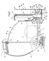
- Number 1 in Figure 1 indicates as a whole a vending machine for products 2, which comprises a cabinet 3 having a wall 4 defining the front of an inner compartment 5 housing a number of superimposed trays for supporting products 2, which are arranged on the relative trays in rows perpendicular to wall 4 and facing an opening formed through a top portion of wall 4 and closed by a door 4a.
- wall 4 comprises a bottom portion having an opening 6, through which is fitted movably a drawer 7 defining a pickup compartment 8 of a pickup device 9, which allows the user to remove from the outside a selected product 2 fed into pickup compartment 8 by a known feed device (not shown) housed inside a gap, which extends between the front ends of the trays and door 4a, is closed at the bottom by drawer 7 when this is in its normal closed position, and communicates directly with the pickup compartment when drawer 7 is in its normal closed position.
- drawer 7 comprises a cup-shaped body 10. bounded by a rectangular bottom box wall 11, by a rectangular front wall 12 and a rectangular rear wall 13 parallel to each other and perpendicular to bottom wall 11, and by two parallel lateral walls 14 perpendicular to bottom wall 11 and walls 12 and 13.
- Drawer 7 also comprises a box body 15 connected to the outer surface of wall 12 and defining a handle 16 of drawer 7.
- Drawer 7 is fitted to wall 4 to rotate with respect to wall 4 about an axis 17 parallel to walls 11, 12 and 13 and extending through walls 14, close to the edge between wall 12 and wall 11.
- Wall 12 is higher than wall 13; each wall 14 is bounded at its free end by a curved edge 18 coaxial with axis 17; and box body 15 is bounded externally, close to where it is connected to wall 11, by a curved surface 19 coaxial with axis 17 and bounded, on the side facing cabinet 3, by a rib 20 parallel to axis 17.
- Drawer 7 swings about axis 17 between a closed position ( Figures 2 , 3 , 5 , 7 , 8 , 10 , 11 ), in which wall 11 is horizontal, cup-shaped body 10 is positioned with its concavity facing upwards to receive a selected product 2 fed downwards in known manner, box body 10 projects outwards of wall 4, and rib 20 is positioned substantially contacting an inner surface of wall 4; and an open position ( Figures 6 , 9 ), in which walls 11 and 12 form an upward-facing dihedron open outwardly at the top to retain product 2, and walls 11 and 13 form a dihedron with its vertex facing the inside of cabinet 3, and its concavity facing outwards, and completely close opening 6 to prevent break-in when drawer 7 is open.
- curved edges 18 move substantially in contact with a top edge 21 of opening 6, and curved surface 19 moves substantially in contact with a bottom edge 22 of opening 6.
- the weight of drawer 7 is distributed about axis 17 so that drawer 7 is subjected at all times to a force - shown schematically by F1 - that tends to keep drawer 7 in or restore it to a stable, balanced closed position.
- force F1 is generated both by the weight distribution of drawer 7 and by springs (not shown) interposed between cabinet 3 and drawer 7, or by the springs (not shown) alone.
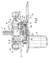
- pickup device 9 comprises an actuating device 23, in turn comprising an actuator 24, and a reversible motor 25 connected to actuator 24 by a transmission 26 to move actuator 24 along a vertical axis 27 and engage drawer 7 to exert a force F2, in opposition to and greater than force F1, on drawer 7 to move it into the open position.
- Pickup device 9 also comprises a central control unit 28 ( Figure 3 ) for controlling motor 25; and a lock device 29 ( Figures 3 , 5 ) operated by motor 25 by means of actuator 24 to lock drawer 7 releasably in the closed position.
- actuating device 23 is fitted to a fixed casing 30 comprising a horizontal plate 31 supporting motor 25 underneath and fitted through with a vertical output pinion 32 of motor 25.
- Pinion 32 meshes with a gear 33, which is fitted in rotary manner to plate 31, is coaxial with axis 27, forms part of transmission 26, and is fitted to a screw 34, which is coaxial with axis 27, is fitted to actuator 24 by a screw-nut screw coupling 35, and defines a straight path for actuator 24.
- casing 30 also comprises a rectangular parallelepiped-shaped housing 36 extending upwards from plate 31, open on the side facing drawer 7, and in turn comprising a top wall 37 supporting the top end of screw 34 in rotary manner; and a vertical rear wall 38 parallel to axes 17 and 27, and having two vertical slits 39, 40 engaged in sliding manner by respective appendixes 41, 42 extending horizontally from actuator 24 and crosswise to axis 17.
- Rear wall 38, slits 39, 40, and appendixes 41, 42 together define an antirotation device 43 for preventing actuator 24 from rotating about axis 27 as it moves along axis 27.
- actuator 24 comprises a substantially rectangular, horizontal plate 44, from the short lateral edges of which two flat brackets 45 project downwards.
- Each bracket 45 is crosswise to axis 17, projects from plate 44, and is fitted, on its free end facing drawer 7, with a pin supporting a roller 46 coaxial with the other roller 46 and rotating about an axis 47 parallel to axis 17.
- plate 44 has only one bracket 45 and one roller 46.
- the actuator 24 also comprises a box body 48 connected to an underside surface of plate 44, housing a nut screw 49 of screw-nut screw coupling 35, and fitted integrally with appendixes 41, 42; and a tooth 50 projecting vertically downwards from plate 44, and which, as explained below, serves as an actuator for lock device 29.
- appendix 41 projects outwards of housing 36, and is fitted with a counter-roller 51, which rolls on the outer surface of rear wall 38 of housing 36 to discharge on housing 36 the forces exchanged between actuator 24 and drawer 7.
- Appendix 42 is L-shaped, and has a horizontal arm 52, which projects from the rear of housing 36, is parallel to rear wall 38, and has a substantially vertical end edge 53 with a top recess 54 and a bottom recess 55. End edge 53 of arm 52 cooperates with a top stop microswitch 56 and a bottom stop microswitch 57, which are connected to central control unit 28, and the function of which, particularly of microswitch 57, is described below.
- Each roller 46 projects laterally outwards of housing 36, is located over a respective end portion 58 of plate 31, and rolls along a track crosswise to the straight path defined by screw 34, and itself defined by an underside surface of a respective rail 59, which is integral with drawer 7, projects rearwards from wall 13 of drawer 7, slopes roughly 45° downwards with respect to wall 13, and is positioned with its free end contacting respective end portion 58 of plate 31 when drawer 7 is in the Figure 2 closed position.
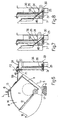
- lock device 29 is fitted to plate 31, and comprises a fork 60 extending upwards from a front portion of plate 31 and fitted with a right-angle rocker arm 61 that oscillates about an axis 62 parallel to axis 17; and a further fork 63 extending upwards from a rear portion of plate 31, and fitted with a right-angle rocker arm 64 that oscillates about an axis 65 also parallel to axis 17.
- Right-angle rocker arm 61 comprises a box arm 66 extending upwards from axis 62 and fitted on its free end with a pin 67, which extends, parallel to axis 62, through a window formed on the free end of arm 66 and housing a catch 68, which oscillates about the axis of pin 67, in opposition to a leaf spring 69 secured to arm 66, from a normal extracted position - in which catch 68 projects outwards of arm 66 and towards drawer 7 to define a catch on arm 66 by which to engage a striker 70 projecting rearwards from the outer surface of wall 13 of drawer 7 - to a withdrawn position, in which catch 68 is housed inside arm 66.
- Rocker arm 61 also comprises an arm 71 extending rearwards from axis 62 and normally held in a lowered position, contacting the topside surface of plate 31, by a spring 72 stretched between an intermediate portion of arm 66 and rear wall 38 of housing 36.
- arm 66 slopes roughly 20° rearwards, and catch 68, even if in the extracted operating position, is positioned clear of striker 70, i.e. outwards of the path travelled by striker 70 as the drawer swings about axis 17.
- arm 71 Close to its free end, arm 71 has a curved slot 73 for connection to rocker arm 64.
- Rocker arm 64 is a double rocker arm substantially parallel to plate 31 and defined by two members on opposite sides of arm 71 and connected to each other by two pins 74, 75 parallel to axis 65, located on opposite sides of axis 55, and of which pin 74, at the front, extends through slot 73 to slide transversely along slot 73, and pin 75 is positioned vertically beneath tooth 50 ( Figures 3 , 4 , 10-12 ) and is moved downwards by tooth 50, as described below, to lift arm 71 of plate 31, move arm 66 forwards, and move catch 68, in the extracted position, into a position of interference ( Figure 11 ), in which catch 68 is positioned with its bottom end directly over striker 70 and substantially contacting a top end of striker 70 when drawer 7 is in the closed position.
- pickup device 9 and drawer 7 will now be described as of the Figure 11 position, in which drawer 7 is in the closed position with walls 12, 13, 14 positioned vertically to receive a selected product 2 downwards in known manner, and is locked in this position by lock device 29. More specifically, in this position, actuator 24 is set to its lowest position, in which microswitch 57 engages top recess 54 in end edge 53 of appendix 42 of plate 44; and tooth 50 presses on pin 75 of rocker arm 64, and, by means of pin 74, keeps arm 71 of right-angle rocker arm 61 raised, and arm 66 moved towards drawer 7, so that catch 68, in the extracted position, is positioned over striker 70 to prevent drawer 7 from swinging about axis 17 into the open position.
- rollers 46 are positioned adjacent to the outer surface of wall 13 of drawer 7 and a pertain distance from respective rails 59.
- a sensor (not shown) detects a product 2 inside drawer 7 and sends a signal to central control unit 28 ( Figure 3 ), which activates motor 25 to rotate screw 34 and so move actuator 24 upwards.
- actuator 24 Powered by motor 25, actuator 24 first performs an initial movement to dislodge microswitch 57 ( Figure 3 ) from top recess 54 into bottom recess 55.
- this initial movement lifts tooth 50 far enough to allow spring 72 to lower arm 71 of right-angle rocker arm 61, and catch 68, still in the extracted position, to move into its position of non-interference with striker 70.
- lock device 29 has no effect on the position of drawer 7, which is maintained in its stable, balanced closed position by force F1 holding the ends of rails 59 in contact with respective end portions 58 of plate 31.
- actuator 24 ( Figure 7 ) also moves rollers 46 closer to but not yet into contact with respective rails 59.
- Microswitch 57 engaging bottom recess 55 does not stop motor 25, which continues to move actuator 24 upwards in a work movement ( Figure 6 ) which is arrested by arm 52 of appendix 42 engaging microswitch 56.
- rollers 46 come into contact with and exert force F2 on respective rails 59 simply by force of contact, thus lifting rails 59 and rotating drawer 7 about axis 17 into the Figure 6 and 9 open position.
- rails 59 move away from actuator 24, with the result that rollers 46 roll along respective rails 59 from positions adjacent to wall 13 ( Figure 7 ) to positions close to the free ends of rails 59 ( Figure 6 ).
- drawer 7 In the open position, drawer 7 is positioned with its top opening facing fully outwards, to allow product 2 to be removed from pickup compartment 8, and at the same time completely closes opening 6, as stated, to prevent break-in.
- central control unit 28 stops motor 25 for a given length of time, normally a few seconds, and then reverses motor 25 to perform a return movement of actuator 24, which is arrested ( Figure 7 ) by microswitch 57 engaging bottom recess 55 in arm 52.
- drawer 7 is returned to the closed position solely by force F1, which is normally opposed by a damper (not shown), which slows down drawer 7 to allow detachment of rollers 46 from respective rails 59.
- central control unit 28 slows motor 25, so actuator 24 simply supports drawer 7 as it moves back into the stable, balanced position, without exerting any force on drawer 7 other than a reaction force to force F1.
- actuator 24 has normally completed its return movement, and stopped ( Figure 7 ), and is positioned with microswitch 57 engaging bottom recess 55 in arm 52.
- central control unit 28 stops motor 25 for a given length of time, normally about thirty seconds, after which motor 25 is started up again to perform a final movement of actuator 24, during which, with drawer 7 stationary, tooth 50 engages pin 75 of rocker arm 64 to move right-angle rocker arm 61 into the lock position ( Figure 11 ).
- drawer 7 If unable to remove product 2 within the open period, the user can grip handle 16 to keep drawer 7 open, In which case, if the drawer is released before actuator 24 completes its return movement, drawer 7, once released, is rotated backwards by force F1 to move rails 59 into contact with end portions 58 of plate 31; from which point on, the closing procedure is the same as described above. Conversely, if the drawer is released after lock device 29 is activated, striker 70 ( Figure 11 ) - as drawer 7 is moved into the closed position by force F1 - engages catch 68, backs it up in opposition to leaf spring 69, and clicks it into the lock position ( Figure 11 ) as drawer 7 reaches the closed position.
Landscapes
- Physics & Mathematics (AREA)
- General Physics & Mathematics (AREA)
- Vending Machines For Individual Products (AREA)
- Drawers Of Furniture (AREA)
- Control Of Vending Devices And Auxiliary Devices For Vending Devices (AREA)
- Threshing Machine Elements (AREA)
Applications Claiming Priority (2)
| Application Number | Priority Date | Filing Date | Title |
|---|---|---|---|
| IT000228A ITTO20080228A1 (it) | 2008-03-26 | 2008-03-26 | Metodo di distribuzione e distributore automatico di prodotti |
| PCT/IB2009/000587 WO2009118607A1 (en) | 2008-03-26 | 2009-03-25 | Product dispensing method and vending machine |
Publications (2)
| Publication Number | Publication Date |
|---|---|
| EP2266103A1 EP2266103A1 (en) | 2010-12-29 |
| EP2266103B1 true EP2266103B1 (en) | 2012-03-14 |
Family
ID=40293295
Family Applications (1)
| Application Number | Title | Priority Date | Filing Date |
|---|---|---|---|
| EP09725703A Active EP2266103B1 (en) | 2008-03-26 | 2009-03-25 | Product dispensing method and vending machine |
Country Status (9)
| Country | Link |
|---|---|
| US (1) | US20110108564A1 (it) |
| EP (1) | EP2266103B1 (it) |
| JP (1) | JP2011515773A (it) |
| CN (1) | CN102027513B (it) |
| AT (1) | ATE549707T1 (it) |
| DK (1) | DK2266103T3 (it) |
| ES (1) | ES2380898T3 (it) |
| IT (1) | ITTO20080228A1 (it) |
| WO (1) | WO2009118607A1 (it) |
Families Citing this family (7)
| Publication number | Priority date | Publication date | Assignee | Title |
|---|---|---|---|---|
| KR101416013B1 (ko) * | 2012-10-17 | 2014-07-08 | 롯데알미늄 주식회사 | 자동판매기용 상품 투출장치 |
| CN104063956A (zh) * | 2013-03-18 | 2014-09-24 | 鸿富锦精密工业(武汉)有限公司 | 自动售货机 |
| SG11201508757UA (en) * | 2013-04-23 | 2015-11-27 | Minibar Systems | Controlled inventory refrigerated dispensing system |
| CN106091539A (zh) * | 2016-06-23 | 2016-11-09 | 南京创维家用电器有限公司 | 一种冰箱 |
| CN107777150B (zh) * | 2017-11-17 | 2023-01-24 | 长沙理工大学 | 一种抽拉式环保木糖醇装置 |
| CN108305389B (zh) * | 2018-01-30 | 2020-07-10 | 乐清市天美贸易有限公司 | 一种商贸用花盆自助售卖装置 |
| CN118140257B (zh) * | 2021-10-21 | 2026-01-02 | 埃沃咖股份公司 | 用于饮料自动售卖机的搅拌棒分配器和用于分配搅拌棒的方法 |
Family Cites Families (21)
| Publication number | Priority date | Publication date | Assignee | Title |
|---|---|---|---|---|
| US2072462A (en) * | 1934-04-25 | 1937-03-02 | Bell Telephone Labor Inc | Coin collector |
| JPS5388198U (it) * | 1976-12-22 | 1978-07-19 | ||
| US4576272A (en) * | 1984-06-21 | 1986-03-18 | The Coca-Cola Company | Counter-top or wall-mounted vending machine |
| US4818854A (en) * | 1986-12-08 | 1989-04-04 | Unisys Corp. | Ticket vending machine |
| US4844567A (en) * | 1987-01-27 | 1989-07-04 | Chalabian Jack S | Vending machine with controlled return access door |
| JPH02168390A (ja) * | 1989-10-18 | 1990-06-28 | Fuji Electric Co Ltd | カップ式飲料自動販売機の商品取出口装置 |
| GB2239863A (en) * | 1990-01-13 | 1991-07-17 | Imi Cornelius | Dispense apparatus |
| JP2903266B2 (ja) * | 1991-08-26 | 1999-06-07 | 東芝機器株式会社 | 自動販売機の扉装置 |
| US5375737A (en) * | 1993-09-29 | 1994-12-27 | Unidynamics Corporation | Vend door assembly |
| US6648220B1 (en) * | 2000-11-14 | 2003-11-18 | Diebold, Incorporated | Cash dispenser and method |
| ITPN20010035A1 (it) * | 2001-05-08 | 2002-11-08 | Necta Vending Solutions Spa | Distributore automatico di prodotti confezionati, dotato di dispositivo antifurto |
| KR100442497B1 (ko) * | 2001-12-17 | 2004-07-30 | 엘지엔시스(주) | 현금자동지급기의 잔류지폐회수장치 |
| KR100425867B1 (ko) * | 2001-12-29 | 2004-04-01 | 엘지엔시스(주) | 현금자동 인출기의 고객 수취장치 |
| KR100425866B1 (ko) * | 2001-12-29 | 2004-04-01 | 엘지엔시스(주) | 현금자동 인출기의 도어 잠금장치 |
| ITPN20020036A1 (it) * | 2002-05-27 | 2003-11-27 | Necta Vending Solutions Spa | Dispositivo antifurto per distributori automatici di prodotti confezionati. |
| CN2624302Y (zh) * | 2003-06-04 | 2004-07-07 | 江苏白雪电器股份有限公司 | 自动售货机的商品输出机构 |
| US20050192705A1 (en) * | 2003-07-01 | 2005-09-01 | Asteres Inc. | Random access and random load dispensing unit |
| US7149600B2 (en) * | 2003-10-08 | 2006-12-12 | Waterfall Inc. | Pipe storage and inventory control chest |
| US8215520B2 (en) * | 2003-10-17 | 2012-07-10 | Rock-Tenn Shared Services, Llc | Secure merchandising system |
| US8047385B2 (en) * | 2004-02-03 | 2011-11-01 | Rtc Industries, Inc. | Product securement and management system |
| US20060266762A1 (en) * | 2005-05-02 | 2006-11-30 | Richard Andrews | Theft deterrent system |
-
2008
- 2008-03-26 IT IT000228A patent/ITTO20080228A1/it unknown
-
2009
- 2009-03-25 WO PCT/IB2009/000587 patent/WO2009118607A1/en not_active Ceased
- 2009-03-25 AT AT09725703T patent/ATE549707T1/de active
- 2009-03-25 US US12/934,565 patent/US20110108564A1/en not_active Abandoned
- 2009-03-25 DK DK09725703.4T patent/DK2266103T3/da active
- 2009-03-25 CN CN2009801148183A patent/CN102027513B/zh active Active
- 2009-03-25 ES ES09725703T patent/ES2380898T3/es active Active
- 2009-03-25 EP EP09725703A patent/EP2266103B1/en active Active
- 2009-03-25 JP JP2011501312A patent/JP2011515773A/ja active Pending
Also Published As
| Publication number | Publication date |
|---|---|
| ITTO20080228A1 (it) | 2009-09-27 |
| ATE549707T1 (de) | 2012-03-15 |
| CN102027513A (zh) | 2011-04-20 |
| WO2009118607A9 (en) | 2010-04-22 |
| JP2011515773A (ja) | 2011-05-19 |
| EP2266103A1 (en) | 2010-12-29 |
| US20110108564A1 (en) | 2011-05-12 |
| ES2380898T3 (es) | 2012-05-21 |
| CN102027513B (zh) | 2013-03-27 |
| WO2009118607A1 (en) | 2009-10-01 |
| DK2266103T3 (da) | 2012-04-10 |
Similar Documents
| Publication | Publication Date | Title |
|---|---|---|
| EP2266103B1 (en) | Product dispensing method and vending machine | |
| EP2232451B1 (en) | Method and device for transferring products in a vending machine | |
| EP2297711B1 (en) | Method of dispensing products off a vending machine tray | |
| US8757433B2 (en) | Dispenser | |
| JP2011521345A (ja) | 製品取り出し方法及び自動販売機 | |
| EP2315898A1 (en) | Self-closing and opening device particularly for a movable furniture part | |
| CN102254377A (zh) | 自动售货机出货结构 | |
| WO2009138863A2 (en) | Beverage vending machine | |
| WO2010091595A1 (zh) | 带减力翻转门板的售货机 | |
| CN106960514A (zh) | 自助式鞋子试穿售卖机 | |
| EP2406773B1 (en) | Product vending machine tray | |
| EP2415031B1 (en) | Product vending machine | |
| CN206601756U (zh) | 自助式鞋子试穿售卖机 | |
| CN210666985U (zh) | 一种联动出货机构及具有该联动出货机构的售货机 | |
| CN208873227U (zh) | 具有自动开门出货式样结构的盒饭柜 | |
| CN209528467U (zh) | 抽拉式储物柜 | |
| CN209015262U (zh) | 一种可实现自动开启关闭的安全防盗门 | |
| CN208737581U (zh) | 一种自动售货机的防盗装置 | |
| CN120808490B (zh) | 自动售货机 | |
| EP2369558B1 (en) | Mechanism for containing and extracting products for vending machines | |
| JP2823471B2 (ja) | 炊飯装置における引出式貯米庫 | |
| EP1300812A2 (en) | Vending machine |
Legal Events
| Date | Code | Title | Description |
|---|---|---|---|
| PUAI | Public reference made under article 153(3) epc to a published international application that has entered the european phase |
Free format text: ORIGINAL CODE: 0009012 |
|
| 17P | Request for examination filed |
Effective date: 20101026 |
|
| AK | Designated contracting states |
Kind code of ref document: A1 Designated state(s): AT BE BG CH CY CZ DE DK EE ES FI FR GB GR HR HU IE IS IT LI LT LU LV MC MK MT NL NO PL PT RO SE SI SK TR |
|
| AX | Request for extension of the european patent |
Extension state: AL BA RS |
|
| DAX | Request for extension of the european patent (deleted) | ||
| GRAP | Despatch of communication of intention to grant a patent |
Free format text: ORIGINAL CODE: EPIDOSNIGR1 |
|
| GRAS | Grant fee paid |
Free format text: ORIGINAL CODE: EPIDOSNIGR3 |
|
| GRAA | (expected) grant |
Free format text: ORIGINAL CODE: 0009210 |
|
| AK | Designated contracting states |
Kind code of ref document: B1 Designated state(s): AT BE BG CH CY CZ DE DK EE ES FI FR GB GR HR HU IE IS IT LI LT LU LV MC MK MT NL NO PL PT RO SE SI SK TR |
|
| REG | Reference to a national code |
Ref country code: GB Ref legal event code: FG4D |
|
| REG | Reference to a national code |
Ref country code: AT Ref legal event code: REF Ref document number: 549707 Country of ref document: AT Kind code of ref document: T Effective date: 20120315 Ref country code: CH Ref legal event code: EP |
|
| REG | Reference to a national code |
Ref country code: DK Ref legal event code: T3 |
|
| REG | Reference to a national code |
Ref country code: IE Ref legal event code: FG4D |
|
| REG | Reference to a national code |
Ref country code: NL Ref legal event code: T3 |
|
| REG | Reference to a national code |
Ref country code: CH Ref legal event code: NV Representative=s name: ANDRE ROLAND S.A. |
|
| REG | Reference to a national code |
Ref country code: DE Ref legal event code: R096 Ref document number: 602009005908 Country of ref document: DE Effective date: 20120510 |
|
| REG | Reference to a national code |
Ref country code: ES Ref legal event code: FG2A Ref document number: 2380898 Country of ref document: ES Kind code of ref document: T3 Effective date: 20120521 |
|
| PG25 | Lapsed in a contracting state [announced via postgrant information from national office to epo] |
Ref country code: HR Free format text: LAPSE BECAUSE OF FAILURE TO SUBMIT A TRANSLATION OF THE DESCRIPTION OR TO PAY THE FEE WITHIN THE PRESCRIBED TIME-LIMIT Effective date: 20120314 Ref country code: NO Free format text: LAPSE BECAUSE OF FAILURE TO SUBMIT A TRANSLATION OF THE DESCRIPTION OR TO PAY THE FEE WITHIN THE PRESCRIBED TIME-LIMIT Effective date: 20120614 Ref country code: LT Free format text: LAPSE BECAUSE OF FAILURE TO SUBMIT A TRANSLATION OF THE DESCRIPTION OR TO PAY THE FEE WITHIN THE PRESCRIBED TIME-LIMIT Effective date: 20120314 |
|
| PGFP | Annual fee paid to national office [announced via postgrant information from national office to epo] |
Ref country code: BE Payment date: 20120403 Year of fee payment: 4 Ref country code: DK Payment date: 20120511 Year of fee payment: 4 |
|
| LTIE | Lt: invalidation of european patent or patent extension |
Effective date: 20120314 |
|
| PG25 | Lapsed in a contracting state [announced via postgrant information from national office to epo] |
Ref country code: LV Free format text: LAPSE BECAUSE OF FAILURE TO SUBMIT A TRANSLATION OF THE DESCRIPTION OR TO PAY THE FEE WITHIN THE PRESCRIBED TIME-LIMIT Effective date: 20120314 Ref country code: GR Free format text: LAPSE BECAUSE OF FAILURE TO SUBMIT A TRANSLATION OF THE DESCRIPTION OR TO PAY THE FEE WITHIN THE PRESCRIBED TIME-LIMIT Effective date: 20120615 Ref country code: FI Free format text: LAPSE BECAUSE OF FAILURE TO SUBMIT A TRANSLATION OF THE DESCRIPTION OR TO PAY THE FEE WITHIN THE PRESCRIBED TIME-LIMIT Effective date: 20120314 |
|
| PG25 | Lapsed in a contracting state [announced via postgrant information from national office to epo] |
Ref country code: CY Free format text: LAPSE BECAUSE OF FAILURE TO SUBMIT A TRANSLATION OF THE DESCRIPTION OR TO PAY THE FEE WITHIN THE PRESCRIBED TIME-LIMIT Effective date: 20120314 |
|
| PG25 | Lapsed in a contracting state [announced via postgrant information from national office to epo] |
Ref country code: MC Free format text: LAPSE BECAUSE OF NON-PAYMENT OF DUE FEES Effective date: 20120331 Ref country code: EE Free format text: LAPSE BECAUSE OF FAILURE TO SUBMIT A TRANSLATION OF THE DESCRIPTION OR TO PAY THE FEE WITHIN THE PRESCRIBED TIME-LIMIT Effective date: 20120314 Ref country code: CZ Free format text: LAPSE BECAUSE OF FAILURE TO SUBMIT A TRANSLATION OF THE DESCRIPTION OR TO PAY THE FEE WITHIN THE PRESCRIBED TIME-LIMIT Effective date: 20120314 Ref country code: SI Free format text: LAPSE BECAUSE OF FAILURE TO SUBMIT A TRANSLATION OF THE DESCRIPTION OR TO PAY THE FEE WITHIN THE PRESCRIBED TIME-LIMIT Effective date: 20120314 Ref country code: IS Free format text: LAPSE BECAUSE OF FAILURE TO SUBMIT A TRANSLATION OF THE DESCRIPTION OR TO PAY THE FEE WITHIN THE PRESCRIBED TIME-LIMIT Effective date: 20120714 Ref country code: RO Free format text: LAPSE BECAUSE OF FAILURE TO SUBMIT A TRANSLATION OF THE DESCRIPTION OR TO PAY THE FEE WITHIN THE PRESCRIBED TIME-LIMIT Effective date: 20120314 Ref country code: PL Free format text: LAPSE BECAUSE OF FAILURE TO SUBMIT A TRANSLATION OF THE DESCRIPTION OR TO PAY THE FEE WITHIN THE PRESCRIBED TIME-LIMIT Effective date: 20120314 Ref country code: SE Free format text: LAPSE BECAUSE OF FAILURE TO SUBMIT A TRANSLATION OF THE DESCRIPTION OR TO PAY THE FEE WITHIN THE PRESCRIBED TIME-LIMIT Effective date: 20120314 |
|
| PG25 | Lapsed in a contracting state [announced via postgrant information from national office to epo] |
Ref country code: SK Free format text: LAPSE BECAUSE OF FAILURE TO SUBMIT A TRANSLATION OF THE DESCRIPTION OR TO PAY THE FEE WITHIN THE PRESCRIBED TIME-LIMIT Effective date: 20120314 Ref country code: PT Free format text: LAPSE BECAUSE OF FAILURE TO SUBMIT A TRANSLATION OF THE DESCRIPTION OR TO PAY THE FEE WITHIN THE PRESCRIBED TIME-LIMIT Effective date: 20120716 |
|
| REG | Reference to a national code |
Ref country code: IE Ref legal event code: MM4A |
|
| PLBE | No opposition filed within time limit |
Free format text: ORIGINAL CODE: 0009261 |
|
| STAA | Information on the status of an ep patent application or granted ep patent |
Free format text: STATUS: NO OPPOSITION FILED WITHIN TIME LIMIT |
|
| PG25 | Lapsed in a contracting state [announced via postgrant information from national office to epo] |
Ref country code: IE Free format text: LAPSE BECAUSE OF NON-PAYMENT OF DUE FEES Effective date: 20120325 |
|
| 26N | No opposition filed |
Effective date: 20121217 |
|
| PG25 | Lapsed in a contracting state [announced via postgrant information from national office to epo] |
Ref country code: MK Free format text: LAPSE BECAUSE OF FAILURE TO SUBMIT A TRANSLATION OF THE DESCRIPTION OR TO PAY THE FEE WITHIN THE PRESCRIBED TIME-LIMIT Effective date: 20120314 |
|
| REG | Reference to a national code |
Ref country code: DE Ref legal event code: R097 Ref document number: 602009005908 Country of ref document: DE Effective date: 20121217 |
|
| PG25 | Lapsed in a contracting state [announced via postgrant information from national office to epo] |
Ref country code: BG Free format text: LAPSE BECAUSE OF FAILURE TO SUBMIT A TRANSLATION OF THE DESCRIPTION OR TO PAY THE FEE WITHIN THE PRESCRIBED TIME-LIMIT Effective date: 20120614 Ref country code: MT Free format text: LAPSE BECAUSE OF FAILURE TO SUBMIT A TRANSLATION OF THE DESCRIPTION OR TO PAY THE FEE WITHIN THE PRESCRIBED TIME-LIMIT Effective date: 20120314 |
|
| BERE | Be: lapsed |
Owner name: N&W GLOBAL VENDING S.P.A. Effective date: 20130331 |
|
| REG | Reference to a national code |
Ref country code: DK Ref legal event code: EBP Effective date: 20130331 Ref country code: DK Ref legal event code: EBP |
|
| REG | Reference to a national code |
Ref country code: CH Ref legal event code: PL |
|
| GBPC | Gb: european patent ceased through non-payment of renewal fee |
Effective date: 20130325 |
|
| PG25 | Lapsed in a contracting state [announced via postgrant information from national office to epo] |
Ref country code: BE Free format text: LAPSE BECAUSE OF NON-PAYMENT OF DUE FEES Effective date: 20130331 Ref country code: CH Free format text: LAPSE BECAUSE OF NON-PAYMENT OF DUE FEES Effective date: 20130331 Ref country code: LI Free format text: LAPSE BECAUSE OF NON-PAYMENT OF DUE FEES Effective date: 20130331 Ref country code: GB Free format text: LAPSE BECAUSE OF NON-PAYMENT OF DUE FEES Effective date: 20130325 |
|
| PG25 | Lapsed in a contracting state [announced via postgrant information from national office to epo] |
Ref country code: DK Free format text: LAPSE BECAUSE OF NON-PAYMENT OF DUE FEES Effective date: 20130331 Ref country code: TR Free format text: LAPSE BECAUSE OF FAILURE TO SUBMIT A TRANSLATION OF THE DESCRIPTION OR TO PAY THE FEE WITHIN THE PRESCRIBED TIME-LIMIT Effective date: 20120314 |
|
| PG25 | Lapsed in a contracting state [announced via postgrant information from national office to epo] |
Ref country code: LU Free format text: LAPSE BECAUSE OF NON-PAYMENT OF DUE FEES Effective date: 20120325 |
|
| PG25 | Lapsed in a contracting state [announced via postgrant information from national office to epo] |
Ref country code: HU Free format text: LAPSE BECAUSE OF FAILURE TO SUBMIT A TRANSLATION OF THE DESCRIPTION OR TO PAY THE FEE WITHIN THE PRESCRIBED TIME-LIMIT Effective date: 20090325 |
|
| REG | Reference to a national code |
Ref country code: AT Ref legal event code: MM01 Ref document number: 549707 Country of ref document: AT Kind code of ref document: T Effective date: 20140325 |
|
| PG25 | Lapsed in a contracting state [announced via postgrant information from national office to epo] |
Ref country code: AT Free format text: LAPSE BECAUSE OF NON-PAYMENT OF DUE FEES Effective date: 20140325 |
|
| REG | Reference to a national code |
Ref country code: FR Ref legal event code: PLFP Year of fee payment: 8 |
|
| REG | Reference to a national code |
Ref country code: FR Ref legal event code: PLFP Year of fee payment: 9 |
|
| REG | Reference to a national code |
Ref country code: FR Ref legal event code: PLFP Year of fee payment: 10 |
|
| P01 | Opt-out of the competence of the unified patent court (upc) registered |
Effective date: 20230530 |
|
| PGFP | Annual fee paid to national office [announced via postgrant information from national office to epo] |
Ref country code: IT Payment date: 20250304 Year of fee payment: 17 |
|
| PGFP | Annual fee paid to national office [announced via postgrant information from national office to epo] |
Ref country code: ES Payment date: 20250415 Year of fee payment: 17 |
|
| PGFP | Annual fee paid to national office [announced via postgrant information from national office to epo] |
Ref country code: DE Payment date: 20260326 Year of fee payment: 18 |
|
| PGFP | Annual fee paid to national office [announced via postgrant information from national office to epo] |
Ref country code: NL Payment date: 20260327 Year of fee payment: 18 |
|
| PGFP | Annual fee paid to national office [announced via postgrant information from national office to epo] |
Ref country code: FR Payment date: 20260326 Year of fee payment: 18 |