EP2267226A2 - Dispositif de commande pour borne rétractable - Google Patents
Dispositif de commande pour borne rétractable Download PDFInfo
- Publication number
- EP2267226A2 EP2267226A2 EP10380081A EP10380081A EP2267226A2 EP 2267226 A2 EP2267226 A2 EP 2267226A2 EP 10380081 A EP10380081 A EP 10380081A EP 10380081 A EP10380081 A EP 10380081A EP 2267226 A2 EP2267226 A2 EP 2267226A2
- Authority
- EP
- European Patent Office
- Prior art keywords
- bollard
- mobile support
- mobile
- fixed
- stationary
- Prior art date
- Legal status (The legal status is an assumption and is not a legal conclusion. Google has not performed a legal analysis and makes no representation as to the accuracy of the status listed.)
- Withdrawn
Links
- 230000005540 biological transmission Effects 0.000 claims abstract description 9
- 239000000463 material Substances 0.000 claims description 7
- 230000005484 gravity Effects 0.000 description 6
- 239000012530 fluid Substances 0.000 description 5
- 238000004873 anchoring Methods 0.000 description 3
- 239000002184 metal Substances 0.000 description 3
- 239000002131 composite material Substances 0.000 description 2
- 229920002994 synthetic fiber Polymers 0.000 description 2
- 230000000712 assembly Effects 0.000 description 1
- 238000000429 assembly Methods 0.000 description 1
- 230000008878 coupling Effects 0.000 description 1
- 238000010168 coupling process Methods 0.000 description 1
- 238000005859 coupling reaction Methods 0.000 description 1
- 230000003247 decreasing effect Effects 0.000 description 1
- 239000013013 elastic material Substances 0.000 description 1
- 238000004519 manufacturing process Methods 0.000 description 1
- 239000007769 metal material Substances 0.000 description 1
- 238000012986 modification Methods 0.000 description 1
- 230000004048 modification Effects 0.000 description 1
- 230000002093 peripheral effect Effects 0.000 description 1
- 230000000717 retained effect Effects 0.000 description 1
Images



Classifications
-
- E—FIXED CONSTRUCTIONS
- E01—CONSTRUCTION OF ROADS, RAILWAYS, OR BRIDGES
- E01F—ADDITIONAL WORK, SUCH AS EQUIPPING ROADS OR THE CONSTRUCTION OF PLATFORMS, HELICOPTER LANDING STAGES, SIGNS, SNOW FENCES, OR THE LIKE
- E01F13/00—Arrangements for obstructing or restricting traffic, e.g. gates, barricades ; Preventing passage of vehicles of selected category or dimensions
- E01F13/04—Arrangements for obstructing or restricting traffic, e.g. gates, barricades ; Preventing passage of vehicles of selected category or dimensions movable to allow or prevent passage
- E01F13/044—Arrangements for obstructing or restricting traffic, e.g. gates, barricades ; Preventing passage of vehicles of selected category or dimensions movable to allow or prevent passage the barrier being formed by obstructing members situated on, flush with, or below the traffic surface, e.g. with inflatable members on the surface
- E01F13/046—Arrangements for obstructing or restricting traffic, e.g. gates, barricades ; Preventing passage of vehicles of selected category or dimensions movable to allow or prevent passage the barrier being formed by obstructing members situated on, flush with, or below the traffic surface, e.g. with inflatable members on the surface the obstructing members moving up in a translatory motion, e.g. telescopic barrier posts
Definitions
- the present invention relates to an operating device for a retractable bollard, of those used, for example, for limiting access, comprising a base box fixed to the ground and buried such that an upper surface thereof is substantially at the level of the ground, and a bollard fixed to a mobile support arranged to guidingly move inside the base box between a position in which the bollard is extended and a position in which the bollard is retracted, where the mentioned operating device is arranged to move the mobile support and the bollard between said extended and retracted positions.
- Patent ES 2168841 T3 discloses a retractable bollard provided with an operating device consisting of an electric motor arranged centrally in the fixed part to rotate a shaft on which belts or cables supported on respective pulleys and fixed at their ends to anchors in the lower part of the mobile support on which the bollard is fixed are wound and unwound.
- an electric motor arranged centrally in the fixed part to rotate a shaft on which belts or cables supported on respective pulleys and fixed at their ends to anchors in the lower part of the mobile support on which the bollard is fixed are wound and unwound.
- a drawback of this device is that, due to the fact that the belts or cables do not actively pull the mobile support and the bollard downwards towards the retracted position, there is a risk that the bollard does not move downwards by gravity due, for example, to debris housed in the guiding means.
- Document GB 2421974 A describes a retractable bollard in which the operating device comprises an electric motor arranged in a side compartment outside the bollard to rotate a reel on which a cable supported on a pulley and connected at its end to an anchor in the lower part of the mobile support incorporating the bollard is wound and unwound.
- the motor rotates in a first direction
- the cable is wound on the reel and pulls the mobile support and the bollard upwards to the extended position.
- the motor rotates in a second opposite direction
- the cable is unwound and allows the mobile support and the bollard to move downwards by gravity to the retracted position.
- a drawback of this device besides the risk of jamming associated with the downward movement by gravity, is that the operating device requires space underground in addition to the space that is strictly necessary for the retractable bollard.
- Document EP 0989237 A2 discloses a retractable bollard provided with an operating device consisting of a telescopic piston formed by a plurality of short sectors having decreasing diameters which are housed inside one another. The uppermost sector also having smaller diameter is directly in contact with a supporting surface of the mobile support incorporating the bollard.
- a fluid under pressure is introduced in the telescopic piston, the latter extends and elevates the mobile support and the bollard upwards to the extended position.
- the telescopic piston is drained of fluid, the mobile support and the bollard can move downwards by gravity to the retracted position.
- a drawback of this device besides the risk of jamming associated with the downward movement by gravity, is that the telescopic piston is a complex component that is not commercially available and is relatively expensive to manufacture.
- Patent application FR-A1-2768756 describes a concealable bollard comprising a lightweight, column-type tubular section hollow body made of a flexible material allowing its deformation, such as a plastic material or a composite material capable of yielding by deformation due to the impact and/or passage of a vehicle without considerably damaging the latter.
- the main body of the bollard is attached to a mobile supporting platform by means of a first attachment by riveting a main part of the bollard to a section close to the base and by the additional retaining of a collar finishing the basal end of the bollard by means of peripheral legs fixed to the platform and superimposed in cantilever on said collar.
- This embodiment can present problems of permanence and durability in relation to a guarantee of the attachment in the event that the bollard is subjected to various impacts during its service life, which is probable.
- Patent FR-B1-2774404 describes a concealable bollard having a hollow tubular section which can be made of a lightweight plastic deformable material.
- the patent explains that the mobile part is attached to the fixed part by magnetic actuation means retaining an end of the tubular body of the bollard with clamp-like securing such that the attachment between the two parts is not a function of a mechanical strength but rather depends on the mutual magnetic attraction of magnetic coupling means used.
- this attachment has drawbacks similar to those mentioned above in that there is no approach to securing which takes into account the particular conditions of the deformable bollard used.
- the present invention contributes to palliating the foregoing and other drawbacks by providing an operating device for a retractable bollard.
- the operating device comprises the combination of a linear actuator having a fixed body connected to a stationary structure and an extendible rod connected by means of a transmission to a mobile support guided linearly with respect to said stationary structure, and on which there is fixed a bollard.
- the mentioned extendible rod of said linear actuator is movable in a direction parallel to the movement direction of said mobile support, and said transmission comprises at least a first flexible pull element and at least a second flexible pull element both connected to a mobile drive element configured to be connected to the mobile support.
- the mentioned first and second flexible pull elements are linked to a distal end of the extendible rod and supported on respective first and second stationary pulleys installed in opposite sides with respect to said mobile drive element.
- the first and second flexible pull elements comprise several spans substantially parallel to said movement direction of the mobile support.
- the first flexible pull element has a first end fixed to a first stationary anchor located in the stationary structure close to said fixed body of the linear actuator, a second end fixed to the mobile drive element, and a section between said first and second ends supported on a first mobile pulley installed in said distal end of the extendible rod and in said first stationary pulley, which is installed in the stationary structure close to an end of the fixed body opposite the extendible rod.
- the second flexible pull element has a first end fixed to said mobile drive element, a second end fixed to a second stationary anchor located in the stationary structure beyond a limit position that can be reached by the distal end of the extendible rod when the latter is extended, and a section between said first and second ends supported on said second stationary pulley, which is installed in the stationary structure close to said limit position that can be reached by the distal end of the extendible rod when the latter is extended, and on a second mobile pulley installed in the distal end of the extendible rod and which is coaxial with said first mobile pulley.
- the mentioned linear actuator can be of any type capable of linearly extending and retracting a rod.
- the linear actuator is a piston and cylinder assembly operated by hydraulic fluid supplied from an external hydraulic station.
- fluid under pressure is introduced into the cylinder in a first side of the piston, the rod is extended and pulls the first flexible pull element while at the same time loosening the second flexible pull element in the same degree, and thereby the first flexible pull element pulls the mobile drive element upwards, which in turn drags the mobile support and the bollard towards the extended position.
- the transmission comprises two of the first flexible parallel drive elements arranged on either side of the linear actuator and a single second flexible pull element arranged between the two first flexible pull elements and facing the linear actuator.
- a highly compact, balanced operating device is thus achieved which is capable of positively operating the movements of the mobile support and the bollard both upwards towards the extended position and downwards towards the retracted position.
- the stationary structure is preferably configured as a hollow column inside which the linear actuator, the first and second flexible pull elements, the mobile drive element and the corresponding pulleys are arranged.
- a longitudinal window facing the path of the mobile drive element is formed in a wall of said hollow column. The mobile drive element can thus be connected to the mobile support and can be shifted between the extended and retracted positions.
- the stationary structure constitutes an autonomous module integrating all the elements related to the operation of the bollard.
- the column formed by the stationary structure is sized to fit in a vertical support in the form of a channel integral with a base box configured to be buried and fixed to the ground, with an upper plate substantially flush with the ground, through an opening of which is extended the bollard.
- the stationary structure and said vertical support include respective fixing configurations provided with openings which, when the stationary structure is fitted in the vertical support, face one another in order to allow inserting a fixing pin.
- the bollard is preferably hollow, and particularly deformable, made from a known plastic or composite material, and the mobile support has the shape of a casing with an upper opening communicating the inside of the mobile support with the inside of the bollard and a lower opening facing the upper opening.
- the stationary structure by virtue of its column form, is installed in a central position in the base box and has a height selected so that it does not protrude from the level of the ground, such that when the bollard is in the retracted position, the stationary structure is inserted through both upper and lower openings of the mobile support and partially penetrates the bollard. Nevertheless, when the bollard is extended the stationary structure is inserted only through the lower opening of the mobile support and does not penetrate the bollard.
- the base box has side walls facing one another in twos and provided with smooth inner surfaces
- the mobile support has fixed in its outer part a plurality of guiding elements, such as, for example, lugs made of a synthetic material with a relatively low coefficient of friction, arranged to slide in contact with said inner surfaces of the base box for guiding the upward and downward linear movements of the mobile support with respect to the base box, and accordingly the movements of the bollard fixed to the mobile support with respect to the stationary structure fixed to the base box.
- guiding elements fixed in the mobile support in cooperation with the walls of the base box provided a simple, reliable, inexpensive and easy-to-install guiding system.
- the body of the bollard is made of an already known- type flexible material used for this application, and has one or more projecting flanges extending outwardly from the perimeter of a lower end of said flexible bollard.
- This flange is supported on and attached to a platform of the mobile support.
- said flange or flanges comprise through orifices through which fixing means, such as studs, pins or screws are arranged, which are fixed by passing through orifices defined in respective areas of an upper face of said mobile support and through holes existing in metal plates configured to be superimposed on said flange before said fixing means are arranged therethrough.
- fixing means such as studs, pins or screws
- a bollard has a single flange by way of a collar next to its basal end.
- the outer face of the lower end of the deformable hollow body and the upper face, or visible face of said flange are attached forming a rounded edge.
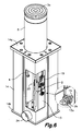
- the mentioned operating device 20 is fixed to a bottom wall 14b of the base box 14 and connected to the mobile support 4 by means of a transmission, such that the operating device can be activated to move the mobile support 4 and the bollard 5 between an extended position (shown in Figures 5 and 6 ), and a retracted position (not shown) in which an upper surface 5a of the bollard 5 is substantially flush with the level of the upper plate 14a of the base box 14 and of the ground.
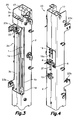
- the operating device 20 comprises a stationary structure 2 which is configured as a hollow column made of sheet metal inside which there is arranged a linear actuator 1, such as a hydraulic cylinder, having a fixed body 1a connected to the stationary structure 2 by a pin 17 and an extendible rod 1b.
- a fork 18 supporting a shaft on which a pair of separate first mobile pulleys 8 and a second mobile pulley 11 located between them are rotatably assembled is fixed at the distal end of the extendible rod.
- a shaft on which a pair of first stationary pulleys 9 is rotatably assembled is fixed in an upper part of the stationary structure 2, close to an end of the fixed body 1a opposite the extendible rod 1b.
- a shaft on which a second stationary pulley 10 is rotatably assembled is fixed at a lower part of the stationary structure 2, close to a limit position that can be reached by the distal end of the extendible rod 1b when the same is extended.
- the operating device furthermore comprises a pair of first twin flexible pull elements 3a and a second flexible pull element 3b, which can be, for example, roller chains, belts or the like.
- the two flexible pull elements 3a are arranged mutually parallel on either side of the linear actuator 1 and the single second flexible pull element 3b is arranged between the two first flexible pull elements 3a and facing the linear actuator 1.
- Each of the first flexible pull elements 3a has a first end fixed to a first stationary anchor 6 located close to the fixed body 1a of the linear actuator 1, a second end fixed to a mobile drive element 7 configured to be connected to the mobile support 4, and a section comprised between said first and second ends that is supported on one of said first mobile pulleys 8 and on one of said first stationary pulleys 9.
- the second flexible pull element 3b has a first end fixed to said mobile drive element 7, a second end fixed to a second stationary anchor 12 located beyond said limit position that can be reached by the distal end of the extendible rod 1b when the same is extended, and a section comprised between said first and second ends that is supported on said second stationary pulley 10 and on said second mobile pulley 11 installed in the distal end of the extendible rod 1b.
- the linear actuator 1 is arranged such that the extendible rod 1b thereof is movable in a direction parallel to the movement direction of the mobile support 4, and the several spans of the first and second flexible pull elements 3a, 3b between pulleys or between pulleys and anchors are substantially parallel to said movement direction of the mobile support 4.
- the first stationary anchors 6 are formed in an anchoring plate 19 fixed to the stationary structure 2 by means of screws passed through elongated holes 19a which allow adjusting the position of the anchoring plate 19 so that the first and second flexible pull elements 3a, 3b are suitably tensed.
- An adjustable stop screw 21 is arranged to assure that the anchoring plate 19 cannot be moved as a consequence of the tension of the flexible pull elements.
- the mobile drive element 7 is thus suspended by the first and second flexible pull elements 3a, 3b and can shift along a path between the respective first and second stationary pulleys 9, 10.
- a longitudinal window 2a facing the mentioned path of the mobile drive element 7 is formed in a wall of the hollow column constituting the stationary structure 2 and the mobile drive element 7 can be connected to the mobile support 4, for example by means of a pin 22, through said longitudinal window 2a.
- the stationary structure 2 furthermore defines supports for end-of-stroke detectors 23a, 23b to detect the limit positions that can be reached by the mobile drive element 7.
- the stationary structure 2 is secured to a vertical support 13, which is in turn fixed to said bottom wall 14b of the base box 14 in a central position.
- the mentioned vertical support 13 has the form of a vertical channel and the stationary structure 2 is sized to fit in said channel of the vertical support 13.
- the stationary structure 2 and the vertical support 13 include respective fixing configurations 2b, 13a provided with facing openings for inserting a fixing pin 15 with a safety device (see the enlarged detail of Figure 6 ).
- the bollard 5 is hollow and the mobile support 4 has an upper opening 4a communicating with the inside of the bollard, 5 and a lower opening 4b aligned with said upper opening 4a, such that the stationary structure 2 in which the operating device 20 is installed is partially inserted into the mobile support 4 through said lower opening 4b of the mobile support 4 when the bollard 5 is in the extended position ( Figure 5 ).
- the stationary structure 2 is inserted in the mobile support 4 and furthermore partially inserted in the bollard 5 through both upper and lower openings 4a, 4b of the mobile support 4.
- a plurality of guiding elements 16 ( Figure 5 ), formed for example by lugs made of a synthetic material with a relatively low coefficient of friction, are fixed externally to the mobile support 4 and arranged to slide in contact with inner surfaces of side walls of said base box 14.
- the base box has four of said side walls facing one another in twos, which are formed by four sheet elements, where each sheet element configures two adjacent side half walls perpendicular to one another, and a corresponding corner.
- One of the mentioned sheet elements has an opening 24 for the passage of cables and/or conduits.
- the flexible bollard 5 has a ring-shaped flange 44 extending outwardly from the perimeter of a lower end 5b of said flexible bollard 5.
- This flange 44 is placed against and secured to a mobile support 4 that is shiftable, by means of linear operating means, through the inside of a base box 14 open at the top and installed in a pit in an way analogous to that described above in relation with Figures 1 to 6 .
- the ring-shaped flange 44 has first through orifices 43 distributed throughout it.
- the flexible bollard 5 could have several separate flanges 44 rather than a unique ring-shaped flange 44.
- second orifices 42 provided with an inner screw threading.
- the mentioned second orifices 42 coincide in opposition with the areas occupied by said first through orifices 43 of the flange 44 of the bollard 5 when the later is in an operative position.
- plates 47 Over the flange 44 there are arranged plates 47 (one of which is separately shown in Figure 10 ) having dimensions and shape adequate to be arranged over different portions of the ring-shaped flange 44, each plate 47 encompassing several of said first through orifices 43.
- Each one of said plates 47 has a series of holes 48 which in an operative position coincide with the first through orifices 43 of the flange 44 of the bollard 5 and with the second orifices 42 of the mobile support 4.
- Fixing elements 45 such as bolts or screws, are inserted through the through holes 48 of the plates 47 and through the first through orifices 43 of the flange 44 of the bollard 5, and screwed in the inner screw threading of the second orifices 42 of the mobile support 4.
- the second orifices 42 of the mobile support 4 could be smooth through orifices and the fixing elements 45 could be screwed or otherwise fixed to external fixing parts, such as nuts or like elements.
- said flange 44 of the bollard 5 which is made of a flexible material, is trapped like a sandwich between the mentioned plate 47 and the mobile support 4, both being made of a metallic material, such that stability in this attachment is guaranteed despite the bollard suffering different impacts and deformation stresses of a greater or lesser degree throughout its service life.
- the outer face of said lower end 5b of the flexible bollard 5 and the upper face of said flange 44 are attached forming a rounded edge 51 having a radius calculated so as to allow the flexible bollard 5 to resist an impact with a determined force, being deformed without breaking.
- the mobile support 4 has vertical walls 41 in the outside of which there are attached guiding elements 16 made of an elastic material, which are also vertically arranged for guiding in a sliding manner the movements of the mobile support 4 with respect the inner wall of said base box 14.
- cover plate parts 14a delimiting a central opening 14c having a diameter greater than that of said flexible bollard 5, which are provided in order to be fixed to a perimetric wall 46 defining the upper opening of the base box 14 by means of one or more nut and screw assemblies 49, 50.
- the cover plate parts 14a cover the flange 44 but allow the flexible bollard 5 to pass through said central opening 14c.
- the operating device according to the present invention described in relation with Figures 1 to 6 can be alternatively applied to the actuation of a rigid bollard or to the actuation of a flexible bollard associated with a fixing device different from that described in relation with Figures 7 to 10 .
- the fixing device associated with the flexible bollard of the present invention described in relation with Figures 7 to 10 can be applied to a flexible bollard associated with an operating device different from that described above in relation with Figures 1 to 6 .
Landscapes
- Engineering & Computer Science (AREA)
- Architecture (AREA)
- Civil Engineering (AREA)
- Structural Engineering (AREA)
- Transmission Devices (AREA)
- Refuge Islands, Traffic Blockers, Or Guard Fence (AREA)
Applications Claiming Priority (2)
| Application Number | Priority Date | Filing Date | Title |
|---|---|---|---|
| ES200901041U ES1070858Y (es) | 2009-06-18 | 2009-06-18 | Dispositivo de accionamiento para una pilona retractil |
| ES200901040U ES1070786Y (es) | 2009-06-18 | 2009-06-18 | Pilona retractil deformable |
Publications (2)
| Publication Number | Publication Date |
|---|---|
| EP2267226A2 true EP2267226A2 (fr) | 2010-12-29 |
| EP2267226A3 EP2267226A3 (fr) | 2015-09-02 |
Family
ID=42738872
Family Applications (1)
| Application Number | Title | Priority Date | Filing Date |
|---|---|---|---|
| EP10380081.9A Withdrawn EP2267226A3 (fr) | 2009-06-18 | 2010-06-18 | Dispositif de commande pour borne rétractable |
Country Status (1)
| Country | Link |
|---|---|
| EP (1) | EP2267226A3 (fr) |
Cited By (2)
| Publication number | Priority date | Publication date | Assignee | Title |
|---|---|---|---|---|
| ITTO20120250A1 (it) * | 2012-03-20 | 2013-09-21 | Came Group S P A | Dispositivo dissuasore illuminato. |
| WO2022147192A1 (fr) * | 2020-12-30 | 2022-07-07 | Neusch Innovations, Lp | Barrière de véhicule déployable à contrepoids |
Citations (5)
| Publication number | Priority date | Publication date | Assignee | Title |
|---|---|---|---|---|
| FR2768756A1 (fr) | 1997-09-25 | 1999-03-26 | Urbaco | Balise routiere legere escamotable |
| EP0989237A2 (fr) | 1998-09-25 | 2000-03-29 | Urbaco | Balise de voirie légère |
| ES2168841T3 (es) | 1998-03-23 | 2002-06-16 | Serge Videmont | Dispositivo para permitir o impedir el paso de un vehiculo, del tipo pilona escamoteable. |
| FR2774404B1 (fr) | 1998-02-03 | 2003-06-20 | Urbaco | Dispositif urbain escamotable |
| GB2421974A (en) | 2005-01-07 | 2006-07-12 | Kenneth Marden Henfrey | Operating mechanism for automatic retractable bollard |
Family Cites Families (2)
| Publication number | Priority date | Publication date | Assignee | Title |
|---|---|---|---|---|
| FR2687702B1 (fr) * | 1992-02-25 | 1994-04-22 | Patrick Vassal | Borne escamotable motorisee. |
| CN101078202B (zh) * | 2007-06-29 | 2010-10-06 | 卢国骥 | 整体密封电动阻隔器 |
-
2010
- 2010-06-18 EP EP10380081.9A patent/EP2267226A3/fr not_active Withdrawn
Patent Citations (5)
| Publication number | Priority date | Publication date | Assignee | Title |
|---|---|---|---|---|
| FR2768756A1 (fr) | 1997-09-25 | 1999-03-26 | Urbaco | Balise routiere legere escamotable |
| FR2774404B1 (fr) | 1998-02-03 | 2003-06-20 | Urbaco | Dispositif urbain escamotable |
| ES2168841T3 (es) | 1998-03-23 | 2002-06-16 | Serge Videmont | Dispositivo para permitir o impedir el paso de un vehiculo, del tipo pilona escamoteable. |
| EP0989237A2 (fr) | 1998-09-25 | 2000-03-29 | Urbaco | Balise de voirie légère |
| GB2421974A (en) | 2005-01-07 | 2006-07-12 | Kenneth Marden Henfrey | Operating mechanism for automatic retractable bollard |
Cited By (5)
| Publication number | Priority date | Publication date | Assignee | Title |
|---|---|---|---|---|
| ITTO20120250A1 (it) * | 2012-03-20 | 2013-09-21 | Came Group S P A | Dispositivo dissuasore illuminato. |
| WO2013140338A1 (fr) * | 2012-03-20 | 2013-09-26 | Came Group S.P.A. | Dispositif de dissuasion éclairé |
| US9328470B2 (en) | 2012-03-20 | 2016-05-03 | Came Group Spa | Illuminated dissuader device |
| WO2022147192A1 (fr) * | 2020-12-30 | 2022-07-07 | Neusch Innovations, Lp | Barrière de véhicule déployable à contrepoids |
| US12312754B2 (en) | 2020-12-30 | 2025-05-27 | Neusch Innovations, Lp | Counterweight deployable vehicle barrier |
Also Published As
| Publication number | Publication date |
|---|---|
| EP2267226A3 (fr) | 2015-09-02 |
Similar Documents
| Publication | Publication Date | Title |
|---|---|---|
| US5557892A (en) | Power mast | |
| US8025090B2 (en) | Garage door operating apparatus and methods | |
| US7607644B1 (en) | Boat lift assembly | |
| US7419204B2 (en) | Powered ramp door lift | |
| US5899401A (en) | Counterbalance device, in particular for a medical x-ray unit, having plural safety devices | |
| US20080060463A1 (en) | Drive device | |
| US7021004B2 (en) | Actuating device | |
| US20110225903A1 (en) | Telescopic mast system | |
| US7159930B2 (en) | Power slide device for vehicle sliding door | |
| US20170260804A1 (en) | Clutch type control device for a cordless blind | |
| US6244324B1 (en) | Barrier | |
| US4727919A (en) | Safety and emergency actuator device for a concertina type door | |
| JP2011207598A (ja) | ブーム及びクレーン | |
| WO2014075042A1 (fr) | Dispositif d'alignement de vitrine | |
| US20210310294A1 (en) | Overhead door lift assembly and tensioner | |
| US20080127560A1 (en) | Garage door opener | |
| US8905115B2 (en) | Blind cord winder integrating with stopping control | |
| US5080200A (en) | Ball screw elevator drive system | |
| EP1483472B1 (fr) | Porte de securite en sections a levage hydraulique | |
| EP2286045B1 (fr) | Mât télescopique | |
| US7506556B2 (en) | Device for opening and closing a vehicle body part | |
| WO2009035607A1 (fr) | Pivot de compression unique | |
| KR20210118388A (ko) | 선박 계선 시스템 및 방법 | |
| US5349703A (en) | Toilet lid for flushing a toilet | |
| CN110240020B (zh) | 可伸缩绞缆机 |
Legal Events
| Date | Code | Title | Description |
|---|---|---|---|
| PUAI | Public reference made under article 153(3) epc to a published international application that has entered the european phase |
Free format text: ORIGINAL CODE: 0009012 |
|
| AK | Designated contracting states |
Kind code of ref document: A2 Designated state(s): AL AT BE BG CH CY CZ DE DK EE ES FI FR GB GR HR HU IE IS IT LI LT LU LV MC MK MT NL NO PL PT RO SE SI SK SM TR |
|
| AX | Request for extension of the european patent |
Extension state: BA ME RS |
|
| PUAL | Search report despatched |
Free format text: ORIGINAL CODE: 0009013 |
|
| AK | Designated contracting states |
Kind code of ref document: A3 Designated state(s): AL AT BE BG CH CY CZ DE DK EE ES FI FR GB GR HR HU IE IS IT LI LT LU LV MC MK MT NL NO PL PT RO SE SI SK SM TR |
|
| AX | Request for extension of the european patent |
Extension state: BA ME RS |
|
| RIC1 | Information provided on ipc code assigned before grant |
Ipc: E01F 13/04 20060101AFI20150728BHEP |
|
| 17P | Request for examination filed |
Effective date: 20160210 |
|
| RBV | Designated contracting states (corrected) |
Designated state(s): AL AT BE BG CH CY CZ DE DK EE ES FI FR GB GR HR HU IE IS IT LI LT LU LV MC MK MT NL NO PL PT RO SE SI SK SM TR |
|
| GRAP | Despatch of communication of intention to grant a patent |
Free format text: ORIGINAL CODE: EPIDOSNIGR1 |
|
| INTG | Intention to grant announced |
Effective date: 20160406 |
|
| STAA | Information on the status of an ep patent application or granted ep patent |
Free format text: STATUS: THE APPLICATION IS DEEMED TO BE WITHDRAWN |
|
| 18D | Application deemed to be withdrawn |
Effective date: 20160817 |