EP2267378A2 - Vorrichtung zur Befestigung von Installationen an wasserdichte Abdeckungen - Google Patents
Vorrichtung zur Befestigung von Installationen an wasserdichte Abdeckungen Download PDFInfo
- Publication number
- EP2267378A2 EP2267378A2 EP10380085A EP10380085A EP2267378A2 EP 2267378 A2 EP2267378 A2 EP 2267378A2 EP 10380085 A EP10380085 A EP 10380085A EP 10380085 A EP10380085 A EP 10380085A EP 2267378 A2 EP2267378 A2 EP 2267378A2
- Authority
- EP
- European Patent Office
- Prior art keywords
- profile
- longitudinal
- tubular core
- cover
- hot
- Prior art date
- Legal status (The legal status is an assumption and is not a legal conclusion. Google has not performed a legal analysis and makes no representation as to the accuracy of the status listed.)
- Withdrawn
Links
- 238000009434 installation Methods 0.000 title claims abstract description 28
- 239000002184 metal Substances 0.000 claims abstract description 33
- 238000004078 waterproofing Methods 0.000 claims abstract description 31
- 239000012943 hotmelt Substances 0.000 claims abstract description 28
- 239000000463 material Substances 0.000 claims abstract description 28
- 230000004888 barrier function Effects 0.000 claims description 5
- 239000004743 Polypropylene Substances 0.000 claims description 4
- -1 polypropylene Polymers 0.000 claims description 4
- 229920001155 polypropylene Polymers 0.000 claims description 4
- 239000012528 membrane Substances 0.000 claims description 3
- XLYOFNOQVPJJNP-UHFFFAOYSA-N water Substances O XLYOFNOQVPJJNP-UHFFFAOYSA-N 0.000 abstract description 10
- 238000009413 insulation Methods 0.000 description 8
- 239000011490 mineral wool Substances 0.000 description 4
- 230000000694 effects Effects 0.000 description 3
- 230000015572 biosynthetic process Effects 0.000 description 2
- 230000008878 coupling Effects 0.000 description 2
- 238000010168 coupling process Methods 0.000 description 2
- 238000005859 coupling reaction Methods 0.000 description 2
- 229910001335 Galvanized steel Inorganic materials 0.000 description 1
- 238000009825 accumulation Methods 0.000 description 1
- 238000004873 anchoring Methods 0.000 description 1
- 238000003491 array Methods 0.000 description 1
- 238000005253 cladding Methods 0.000 description 1
- 238000010276 construction Methods 0.000 description 1
- 238000005265 energy consumption Methods 0.000 description 1
- 239000008397 galvanized steel Substances 0.000 description 1
- 238000012423 maintenance Methods 0.000 description 1
- 239000004033 plastic Substances 0.000 description 1
- 238000004321 preservation Methods 0.000 description 1
- 230000001105 regulatory effect Effects 0.000 description 1
Images


Classifications
-
- F—MECHANICAL ENGINEERING; LIGHTING; HEATING; WEAPONS; BLASTING
- F24—HEATING; RANGES; VENTILATING
- F24S—SOLAR HEAT COLLECTORS; SOLAR HEAT SYSTEMS
- F24S25/00—Arrangement of stationary mountings or supports for solar heat collector modules
- F24S25/10—Arrangement of stationary mountings or supports for solar heat collector modules extending in directions away from a supporting surface
- F24S25/16—Arrangement of interconnected standing structures; Standing structures having separate supporting portions for adjacent modules
-
- F—MECHANICAL ENGINEERING; LIGHTING; HEATING; WEAPONS; BLASTING
- F24—HEATING; RANGES; VENTILATING
- F24S—SOLAR HEAT COLLECTORS; SOLAR HEAT SYSTEMS
- F24S25/00—Arrangement of stationary mountings or supports for solar heat collector modules
- F24S25/30—Arrangement of stationary mountings or supports for solar heat collector modules using elongate rigid mounting elements extending substantially along the supporting surface, e.g. for covering buildings with solar heat collectors
-
- F—MECHANICAL ENGINEERING; LIGHTING; HEATING; WEAPONS; BLASTING
- F24—HEATING; RANGES; VENTILATING
- F24S—SOLAR HEAT COLLECTORS; SOLAR HEAT SYSTEMS
- F24S25/00—Arrangement of stationary mountings or supports for solar heat collector modules
- F24S2025/80—Special profiles
-
- F—MECHANICAL ENGINEERING; LIGHTING; HEATING; WEAPONS; BLASTING
- F24—HEATING; RANGES; VENTILATING
- F24S—SOLAR HEAT COLLECTORS; SOLAR HEAT SYSTEMS
- F24S25/00—Arrangement of stationary mountings or supports for solar heat collector modules
- F24S2025/80—Special profiles
- F24S2025/802—Special profiles having circular or oval cross-section
-
- F—MECHANICAL ENGINEERING; LIGHTING; HEATING; WEAPONS; BLASTING
- F24—HEATING; RANGES; VENTILATING
- F24S—SOLAR HEAT COLLECTORS; SOLAR HEAT SYSTEMS
- F24S80/00—Details, accessories or component parts of solar heat collectors not provided for in groups F24S10/00-F24S70/00
- F24S2080/01—Selection of particular materials
-
- Y—GENERAL TAGGING OF NEW TECHNOLOGICAL DEVELOPMENTS; GENERAL TAGGING OF CROSS-SECTIONAL TECHNOLOGIES SPANNING OVER SEVERAL SECTIONS OF THE IPC; TECHNICAL SUBJECTS COVERED BY FORMER USPC CROSS-REFERENCE ART COLLECTIONS [XRACs] AND DIGESTS
- Y02—TECHNOLOGIES OR APPLICATIONS FOR MITIGATION OR ADAPTATION AGAINST CLIMATE CHANGE
- Y02B—CLIMATE CHANGE MITIGATION TECHNOLOGIES RELATED TO BUILDINGS, e.g. HOUSING, HOUSE APPLIANCES OR RELATED END-USER APPLICATIONS
- Y02B10/00—Integration of renewable energy sources in buildings
- Y02B10/20—Solar thermal
-
- Y—GENERAL TAGGING OF NEW TECHNOLOGICAL DEVELOPMENTS; GENERAL TAGGING OF CROSS-SECTIONAL TECHNOLOGIES SPANNING OVER SEVERAL SECTIONS OF THE IPC; TECHNICAL SUBJECTS COVERED BY FORMER USPC CROSS-REFERENCE ART COLLECTIONS [XRACs] AND DIGESTS
- Y02—TECHNOLOGIES OR APPLICATIONS FOR MITIGATION OR ADAPTATION AGAINST CLIMATE CHANGE
- Y02E—REDUCTION OF GREENHOUSE GAS [GHG] EMISSIONS, RELATED TO ENERGY GENERATION, TRANSMISSION OR DISTRIBUTION
- Y02E10/00—Energy generation through renewable energy sources
- Y02E10/40—Solar thermal energy, e.g. solar towers
- Y02E10/47—Mountings or tracking
Definitions
- the present invention relates to a device for fixing installations to waterproofed covers, both for roofs and façades, and preferably to "Deck" type covers having an external hot-melt waterproofing sheet.
- This device is applicable to the fixation of installations and other elements, such as external cladding, to waterproofed covers, both for roofs and façades.
- Non-transitable “Deck” covers generally consist of thermal and acoustic insulation, mainly consisting of rigid rock wool panels and a metal plate, covered by a self-protected waterproofing sheet made of hot-melt material.
- Fixation of different installations to these covers requires preservation of the watertightness of the waterproofing sheet to prevent the appearance of damp and the formation of water leaks and humidity in the rock wool insulation, with the ensuing increase in the weight of the cover and risk of collapsing.
- the device for fixing installations to waterproofed covers that is the object of this invention has technical peculiarities destined for allowing stable fixation of different installations, for example solar installations, to a cover having an external waterproofing sheet made of hot-melt material, such as a "Deck" type cover, without damaging the waterproofing of the cover.
- the fixing device comprises: a profile made of hot-melt material having a longitudinal housing that extends along the bottom into coplanar flaps for fixation thereof to the waterproofing sheet of the cover, and a metal tubular core, tightly disposed in the interior of the aforementioned longitudinal housing of the profile made of hot-melt material, the aforementioned housing containing the metal tubular core forming an area suitable for assembling and fixing the solar installation without the screws or fixing elements directly perforating the waterproofing sheet of the cover.
- the hot-melt material of the profile is polypropylene, due to which it can be fixed directly to the waterproofing sheet of the cover by application of heat, for example with a blowtorch, avoiding perforation thereof.
- the metal tubular core inserted in the longitudinal housing of the profile consists of a galvanized steel tube, providing an adequate support for coupling self-boring screws wherewith the plate and profiles of the solar installation are coupled.
- the longitudinal layout of the metal tubular core in the interior of the profile made of hot-melt material determines that the weight of the installations assembled on the fixing device will be distributed over a wide area of the cover, rather than transmitted to said cover on specific occasions.
- These fixing devices are disposed on the cover in such a manner that they are spaced approximately so that the solar installation is coupled thereto and not to the insulation of the cover. Additionally, their optimal layout must prevent the accumulation of rain water, due to which they are best oriented in the direction of the maximum slope angle of the cover, taking into account the orientation of the plates of the aforementioned solar installation.
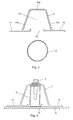
- the profile has an omega-shaped cross-section with a lower opening for introducing the tubular core inside a housing. Additionally, the profile also has a flat upper face parallel to the plane defined by the flaps and having two sloping faces on either side, forming an open angle for lateral anchoring.
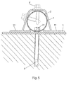
- the metal tubular core may be mechanically fixed to the cover by means of a screw that will pass through the waterproofing and insulation, on specific occasions and according to the corresponding calculation. Once the tube has been fixed to the cover it will be sheathed with the polypropylene profile via the lower opening, in order to cover it while maintaining the watertightness of the cover at the point of fixation of the screw.
- the tubular core has also been envisaged to have a quadrangular cross-section, conferring greater inertia thereto and resistance to the lateral stress transmitted by the solar installation.
- the tubular core has a trapezoidal cross-section appropriate to the housing of the profile made of hot-melt material and defined by: a flat upper surface; two sloping sides, downwardly divergent, having the same number of longitudinal recesses at the lower ends; and a lower surface that rests on the cover having a longitudinal adzing centrally disposed thereon and recessed with respect to said lower surface, and longitudinal drainage channels defined internally and disposed on the opposite sides of the aforementioned longitudinal adzing.
- the metal tubular core has, on its upper surface, an orifice for the pass-through assembly of a screw for fixation to the cover, which passes through a second orifice defined on the upper surface of the longitudinal adzing of the lower surface, whereupon the head of the screw acts upon said longitudinal adzing by means of an elastic washer disposed between the head of the screw and the aforementioned upper surface of the longitudinal adzing.
- the joint interposed between the head of the fixing screw and the upper surface of the recessed longitudinal adzing prevents water or humidity from entering therethrough towards the cover.
- the device also comprises an elastic joint disposed in the interior of the longitudinal adzing recessed with respect to the lower surface of the metal tubular core, said elastic joint having an orifice for the tight passage of the corresponding screw for fixation to the cover.
- the elastic joint is tightened against the waterproofing sheet of the cover, preventing water or humidity from entering through the screw passage orifice.
- the device of the invention additionally comprises a metal bridge by way of an inverted U-shape, having a waterproof membrane on its lower side and disposed on the upper part of the hot-melt profile for covering, at least, those areas corresponding to the orifices defined on the upper surface of the metal tubular core, preventing water from accessing the interior of the metal core through said orifice towards the interior of the metal core.
- the aforementioned elements guarantee total watertightness of the passage orifices of the screw for fixation of the metal core to the cover and, consequently, the passage of water towards the interior of the cover.
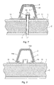
- the profile made of hot-melt material internally comprises longitudinal projections for interlocking into the longitudinal recesses defined on the sloping sides of the metal tubular core.
- the profile made of hot-melt material that covers the metal tubular core has been envisaged to consist of a bituminous material, the side flaps of which are fixed to the waterproofing sheet of the cover by application of heat.
- This constitution of the profile made of hot-melt material is especially recommended in those cases where the waterproofing sheet of the cover is also formed from a bituminous material, providing, in this case correct fixation between the profile made of hot-melt material and the waterproofing sheet.
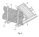
- this device comprises poles fixed to the upper surface of the profile made of hot-melt material, for supporting perforated vertical plates that form a windbreak barrier around the solar plates assembled on the device for fixation thereof to the cover.
- This windbreak barrier minimizes the effect of the wind on the solar plates and consequently the overloads, caused by wind gusts, transmitted to the device for fixation thereof to the cover.
- the fixing device comprises a profile (1) made of hot-melt plastic material destined for fixation to the waterproofing sheet (L) of the cover (C) by application of heat, said profile (1) having a metal tubular core (2) which forms an adequate area for fixing the screws (T) of the installation to be assembled, for example a solar installation (S).
- the profile (2) has a longitudinal housing (13) wherein the tubular core (2) is disposed, said profile (1) extending along the lower lateral area into two flat, coplanar flaps (11) destined for fixing to the waterproofing sheet (L) of the cover by application of heat.
- the housing (13) has a lower opening (12) between the flaps (11) for the lateral introduction of the metal tubular core (2), although the possibility that the aforementioned housing (13) can have a closed contour, housing the tubular core (2) therein, cannot be ruled out.
- the profile (1) has, externally and in correspondence to the housing (13), an upper face (14a) and two lateral faces (14b) for supporting and coupling the solar installations (S) and the introduction of screws (T) that are fixed to the tubular core (2) without damaging the waterproofing sheet of the cover.
- the upper face (14a) is substantially parallel to the flaps (11), while the two lateral faces (14b) are inclined in an oblique direction.
- the profile (1) made of hot-melt material has an omega-shaped cross-section wherein the metal tubular core (2) is tightly housed, which in this example of embodiment has a trapezoidal cross-section appropriate to the housing (3) of the profile (1) and defined by: a flat upper surface (21); two sloping sides (22), divergent towards the lower area, having the same number of longitudinal recesses (23) at the lower ends; and a lower bearing surface (24) having a centrally recessed longitudinal adzing (25) and longitudinal drainage channels (26) internally defined and disposed on the opposite sides of the aforementioned longitudinal adzing (25).
- the metal tubular core (2) has, on its upper surface, an orifice (27) for the pass-through assembly of the screw (3) for fixation to the cover (C), which passes through a second orifice (28) defined on the upper surface of the longitudinal adzing (25) and which establishes the fixation of the tubular core (2) to the cover (C).
- the device comprises an elastic joint (5) disposed in the interior of the longitudinal adzing (25) to guarantee watertightness around the orifice defined on the waterproofing sheet (L) of the cover (C) for passage of the fixing screw (3).
- the hot-melt profile (1) is disposed on a metal bridge (6) by way of an inverted U-shape, having a waterproof membrane (61) for covering and obstructing the orifice (27) defined on the upper surface of the metal tubular core (2).
- the profile (1) is formed from a self-protected bituminous material.
- Figure 8 shows a variant of embodiment wherein the profile (1) is made of polypropylene and has internal longitudinal projections (15) for interlocking into the longitudinal recesses (23) defined on the sloping sides of the tubular core (2).
- the profile (1) is fixed to the waterproofing sheet (L) of the cover (C) by means of lateral flaps (11) and by application of heat.
- the device comprises, as can be observed in figure 9 , poles (7) fixed to the upper surface of the profile (1) for supporting perforated vertical plates (71) that form a windbreak barrier around the assembled plates or solar plate arrays (P), by means of an adequate substructure or installation (S), on the fixing device.
Landscapes
- Engineering & Computer Science (AREA)
- Physics & Mathematics (AREA)
- Life Sciences & Earth Sciences (AREA)
- Sustainable Development (AREA)
- Sustainable Energy (AREA)
- Thermal Sciences (AREA)
- Chemical & Material Sciences (AREA)
- Combustion & Propulsion (AREA)
- Mechanical Engineering (AREA)
- General Engineering & Computer Science (AREA)
- Building Environments (AREA)
- Forms Removed On Construction Sites Or Auxiliary Members Thereof (AREA)
Applications Claiming Priority (2)
| Application Number | Priority Date | Filing Date | Title |
|---|---|---|---|
| ES200901043U ES1070860Y (es) | 2009-06-24 | 2009-06-24 | Dispositivo para la fijacion de instalaciones sobre cubiertas impermeabilizadas |
| ES201030593U ES1072962Y (es) | 2010-06-08 | 2010-06-08 | Dispositivo para la fijacion de instalaciones sobre cubiertas impermeabilizadas |
Publications (2)
| Publication Number | Publication Date |
|---|---|
| EP2267378A2 true EP2267378A2 (de) | 2010-12-29 |
| EP2267378A3 EP2267378A3 (de) | 2014-01-08 |
Family
ID=42801109
Family Applications (1)
| Application Number | Title | Priority Date | Filing Date |
|---|---|---|---|
| EP10380085.0A Withdrawn EP2267378A3 (de) | 2009-06-24 | 2010-06-22 | Vorrichtung zur Befestigung von Installationen an wasserdichte Abdeckungen |
Country Status (1)
| Country | Link |
|---|---|
| EP (1) | EP2267378A3 (de) |
Cited By (5)
| Publication number | Priority date | Publication date | Assignee | Title |
|---|---|---|---|---|
| JP2016214063A (ja) * | 2015-04-30 | 2016-12-15 | 大成建設株式会社 | 太陽電池アレイ群 |
| JP2019161793A (ja) * | 2018-03-09 | 2019-09-19 | 大成建設株式会社 | 太陽電池アレイの支持構造 |
| US10505492B2 (en) | 2016-02-12 | 2019-12-10 | Solarcity Corporation | Building integrated photovoltaic roofing assemblies and associated systems and methods |
| WO2022125630A1 (en) * | 2020-12-11 | 2022-06-16 | Gamechange Solar Corp. | Wind break end plate for solar panel arrays |
| JP2025043886A (ja) * | 2023-09-19 | 2025-04-01 | 三晃金属工業株式会社 | ソーラー屋根装置 |
Family Cites Families (5)
| Publication number | Priority date | Publication date | Assignee | Title |
|---|---|---|---|---|
| DE2558612A1 (de) * | 1975-12-24 | 1977-07-07 | Zink Walter | Transparente kunststoffplatte |
| DE202006019837U1 (de) * | 2005-11-05 | 2007-04-12 | Futurefasteningsystems Solartr | Tragkonstruktionsvorrichtung für Solaranlagen auf Flachdächern |
| EP1783440A3 (de) * | 2005-11-05 | 2009-01-14 | FutureFasteningSystems Solarträgertechnik GmbH & Co. KG | Tragkonstruktionsvorrichtung für Solaranlagen auf Flachdächern |
| GB0610031D0 (en) * | 2006-05-19 | 2006-06-28 | Solar Century Holdings Ltd | Solar panel roof mounting system |
| EP2042822A3 (de) * | 2007-09-25 | 2011-01-05 | Herbert H. W. Metzger | Solarenergie-Komplettsystem |
-
2010
- 2010-06-22 EP EP10380085.0A patent/EP2267378A3/de not_active Withdrawn
Non-Patent Citations (1)
| Title |
|---|
| None |
Cited By (7)
| Publication number | Priority date | Publication date | Assignee | Title |
|---|---|---|---|---|
| JP2016214063A (ja) * | 2015-04-30 | 2016-12-15 | 大成建設株式会社 | 太陽電池アレイ群 |
| US10505492B2 (en) | 2016-02-12 | 2019-12-10 | Solarcity Corporation | Building integrated photovoltaic roofing assemblies and associated systems and methods |
| JP2019161793A (ja) * | 2018-03-09 | 2019-09-19 | 大成建設株式会社 | 太陽電池アレイの支持構造 |
| JP6997017B2 (ja) | 2018-03-09 | 2022-01-17 | 大成建設株式会社 | 太陽電池アレイの支持構造 |
| WO2022125630A1 (en) * | 2020-12-11 | 2022-06-16 | Gamechange Solar Corp. | Wind break end plate for solar panel arrays |
| ES2946558R1 (es) * | 2020-12-11 | 2024-04-15 | Gamechange Solar Corp | Placa cortavientos para conjuntos de paneles solares |
| JP2025043886A (ja) * | 2023-09-19 | 2025-04-01 | 三晃金属工業株式会社 | ソーラー屋根装置 |
Also Published As
| Publication number | Publication date |
|---|---|
| EP2267378A3 (de) | 2014-01-08 |
Similar Documents
| Publication | Publication Date | Title |
|---|---|---|
| US10947731B2 (en) | Supporting a load on a roof | |
| CA2749162C (en) | Support for roof penetrating structures | |
| US5287670A (en) | Double roofing roof structure | |
| CN104160103B (zh) | 储罐隔热接头装置和方法 | |
| EP2267378A2 (de) | Vorrichtung zur Befestigung von Installationen an wasserdichte Abdeckungen | |
| JP6325258B2 (ja) | 建物外部構築物 | |
| KR101375896B1 (ko) | 조립식 건축물의 지붕 누수방지를 위한 체결구 | |
| KR20170099093A (ko) | 옥상방수시스템 | |
| JP5791027B2 (ja) | 太陽電池モジュール設置構造 | |
| KR100806634B1 (ko) | 폴리에스테르 강화 pvc 방수 시트와 단부 실링재의열화방지 캡을 이용한 옥상의 방수 구조 | |
| KR20130082092A (ko) | 과압 완화 지붕 패널 | |
| JP3206829U (ja) | 補強土台の屋根へ設置構造 | |
| JPH0849378A (ja) | 太陽電池パネルを備えた屋根構造 | |
| JP4651572B2 (ja) | 勾配対応型換気棟 | |
| KR101174043B1 (ko) | 건축 구조물의 지붕 구조 및 건축 구조물의 신설 지붕 건축 방법 | |
| JP6693717B2 (ja) | 屋根構造および建物 | |
| JP5098664B2 (ja) | 棟換気装置、及び該棟換気装置を用いた棟部の換気構造 | |
| JP5057776B2 (ja) | 雪庇防止金物 | |
| JP6912195B2 (ja) | 太陽光発電装置を備えた屋根構造 | |
| JP6863790B2 (ja) | 雪止具、屋根構造および建物 | |
| JP6871033B2 (ja) | 雪止部材、屋根構造および建物 | |
| FI127019B (en) | Sandwich element Wall | |
| JP2024017856A (ja) | 通気見切り部材 | |
| JP2008082034A (ja) | 換気棟構造及び換気屋根構造 | |
| FI20195528A1 (fi) | Järjestely veden johtamiseksi pois rakennuksen katolta ja rakennus |
Legal Events
| Date | Code | Title | Description |
|---|---|---|---|
| PUAI | Public reference made under article 153(3) epc to a published international application that has entered the european phase |
Free format text: ORIGINAL CODE: 0009012 |
|
| 17P | Request for examination filed |
Effective date: 20101109 |
|
| AK | Designated contracting states |
Kind code of ref document: A2 Designated state(s): AL AT BE BG CH CY CZ DE DK EE ES FI FR GB GR HR HU IE IS IT LI LT LU LV MC MK MT NL NO PL PT RO SE SI SK SM TR |
|
| AX | Request for extension of the european patent |
Extension state: BA ME RS |
|
| PUAL | Search report despatched |
Free format text: ORIGINAL CODE: 0009013 |
|
| AK | Designated contracting states |
Kind code of ref document: A3 Designated state(s): AL AT BE BG CH CY CZ DE DK EE ES FI FR GB GR HR HU IE IS IT LI LT LU LV MC MK MT NL NO PL PT RO SE SI SK SM TR |
|
| AX | Request for extension of the european patent |
Extension state: BA ME RS |
|
| RIC1 | Information provided on ipc code assigned before grant |
Ipc: F24J 2/52 20060101AFI20131205BHEP Ipc: E04D 13/18 20060101ALI20131205BHEP Ipc: F24J 2/46 20060101ALN20131205BHEP |
|
| STAA | Information on the status of an ep patent application or granted ep patent |
Free format text: STATUS: THE APPLICATION IS DEEMED TO BE WITHDRAWN |
|
| 18D | Application deemed to be withdrawn |
Effective date: 20140709 |