EP2267564A2 - Système et procédé de détermination de l'intégration de procédé - Google Patents
Système et procédé de détermination de l'intégration de procédé Download PDFInfo
- Publication number
- EP2267564A2 EP2267564A2 EP10166643A EP10166643A EP2267564A2 EP 2267564 A2 EP2267564 A2 EP 2267564A2 EP 10166643 A EP10166643 A EP 10166643A EP 10166643 A EP10166643 A EP 10166643A EP 2267564 A2 EP2267564 A2 EP 2267564A2
- Authority
- EP
- European Patent Office
- Prior art keywords
- integrated
- tool
- processes
- tooling
- determining
- Prior art date
- Legal status (The legal status is an assumption and is not a legal conclusion. Google has not performed a legal analysis and makes no representation as to the accuracy of the status listed.)
- Granted
Links
Images


Classifications
-
- G—PHYSICS
- G05—CONTROLLING; REGULATING
- G05B—CONTROL OR REGULATING SYSTEMS IN GENERAL; FUNCTIONAL ELEMENTS OF SUCH SYSTEMS; MONITORING OR TESTING ARRANGEMENTS FOR SUCH SYSTEMS OR ELEMENTS
- G05B19/00—Program-control systems
- G05B19/02—Program-control systems electric
- G05B19/18—Numerical control [NC], i.e. automatically operating machines, in particular machine tools, e.g. in a manufacturing environment, so as to execute positioning, movement or co-ordinated operations by means of program data in numerical form
- G05B19/4093—Numerical control [NC], i.e. automatically operating machines, in particular machine tools, e.g. in a manufacturing environment, so as to execute positioning, movement or co-ordinated operations by means of program data in numerical form characterised by part programming, e.g. entry of geometrical information as taken from a technical drawing, combining this with machining and material information to obtain control information, named part program, for the NC machine
- G05B19/40937—Numerical control [NC], i.e. automatically operating machines, in particular machine tools, e.g. in a manufacturing environment, so as to execute positioning, movement or co-ordinated operations by means of program data in numerical form characterised by part programming, e.g. entry of geometrical information as taken from a technical drawing, combining this with machining and material information to obtain control information, named part program, for the NC machine concerning programming of machining or material parameters, pocket machining
- G05B19/40938—Tool management
-
- G—PHYSICS
- G05—CONTROLLING; REGULATING
- G05B—CONTROL OR REGULATING SYSTEMS IN GENERAL; FUNCTIONAL ELEMENTS OF SUCH SYSTEMS; MONITORING OR TESTING ARRANGEMENTS FOR SUCH SYSTEMS OR ELEMENTS
- G05B2219/00—Program-control systems
- G05B2219/30—Nc systems
- G05B2219/31—From computer integrated manufacturing till monitoring
- G05B2219/31407—Machining, work, process finish time estimation, calculation
-
- G—PHYSICS
- G05—CONTROLLING; REGULATING
- G05B—CONTROL OR REGULATING SYSTEMS IN GENERAL; FUNCTIONAL ELEMENTS OF SUCH SYSTEMS; MONITORING OR TESTING ARRANGEMENTS FOR SUCH SYSTEMS OR ELEMENTS
- G05B2219/00—Program-control systems
- G05B2219/30—Nc systems
- G05B2219/32—Operator till task planning
- G05B2219/32257—Tool replacement minimization
-
- G—PHYSICS
- G05—CONTROLLING; REGULATING
- G05B—CONTROL OR REGULATING SYSTEMS IN GENERAL; FUNCTIONAL ELEMENTS OF SUCH SYSTEMS; MONITORING OR TESTING ARRANGEMENTS FOR SUCH SYSTEMS OR ELEMENTS
- G05B2219/00—Program-control systems
- G05B2219/30—Nc systems
- G05B2219/36—Nc in input of data, input key till input tape
- G05B2219/36284—Use of database for machining parameters, material, cutting method, tools
-
- G—PHYSICS
- G05—CONTROLLING; REGULATING
- G05B—CONTROL OR REGULATING SYSTEMS IN GENERAL; FUNCTIONAL ELEMENTS OF SUCH SYSTEMS; MONITORING OR TESTING ARRANGEMENTS FOR SUCH SYSTEMS OR ELEMENTS
- G05B2219/00—Program-control systems
- G05B2219/30—Nc systems
- G05B2219/36—Nc in input of data, input key till input tape
- G05B2219/36357—Tool line up, select right order of tool, optimal tool order loading, tool file
-
- G—PHYSICS
- G05—CONTROLLING; REGULATING
- G05B—CONTROL OR REGULATING SYSTEMS IN GENERAL; FUNCTIONAL ELEMENTS OF SUCH SYSTEMS; MONITORING OR TESTING ARRANGEMENTS FOR SUCH SYSTEMS OR ELEMENTS
- G05B2219/00—Program-control systems
- G05B2219/30—Nc systems
- G05B2219/36—Nc in input of data, input key till input tape
- G05B2219/36362—Tool change time as function of location in tool magazine, index
-
- G—PHYSICS
- G05—CONTROLLING; REGULATING
- G05B—CONTROL OR REGULATING SYSTEMS IN GENERAL; FUNCTIONAL ELEMENTS OF SUCH SYSTEMS; MONITORING OR TESTING ARRANGEMENTS FOR SUCH SYSTEMS OR ELEMENTS
- G05B2219/00—Program-control systems
- G05B2219/30—Nc systems
- G05B2219/36—Nc in input of data, input key till input tape
- G05B2219/36365—Program so that minimal tool changes are needed
-
- Y—GENERAL TAGGING OF NEW TECHNOLOGICAL DEVELOPMENTS; GENERAL TAGGING OF CROSS-SECTIONAL TECHNOLOGIES SPANNING OVER SEVERAL SECTIONS OF THE IPC; TECHNICAL SUBJECTS COVERED BY FORMER USPC CROSS-REFERENCE ART COLLECTIONS [XRACs] AND DIGESTS
- Y02—TECHNOLOGIES OR APPLICATIONS FOR MITIGATION OR ADAPTATION AGAINST CLIMATE CHANGE
- Y02P—CLIMATE CHANGE MITIGATION TECHNOLOGIES IN THE PRODUCTION OR PROCESSING OF GOODS
- Y02P90/00—Enabling technologies with a potential contribution to greenhouse gas [GHG] emissions mitigation
- Y02P90/02—Total factory control, e.g. smart factories, flexible manufacturing systems [FMS] or integrated manufacturing systems [IMS]
Definitions
- the invention relates to a system and method that are used to determine an optimal process for forming a product shape from a material shape.
- JP-A-11-235646 A system that determines a machining process is, for example, described in Japanese Patent Application Publication No. 11-235646 ( JP-A-11-235646 ). JP-A-11-235646 describes that, when there are a plurality of process candidates, processes are integrated to minimize actual machining time.
- the invention provides a process determining system and method that most appropriately integrate processes in consideration of factors other than (or in addition to) an actual machining time to thereby make it possible to determine an optimal process.
- the integrated process is determined to be optimal when a time obtained by multiplying the unit integration reduction time by the number of individual processes integrated is longer than the elongated (or increase in) actual machining time.
- a similarity between toolings is considered in order to integrate processes, and an element of a similarity is any one of a type of tool, a type of holder, a tool projection length and an edge diameter of a tool, so it is possible to reliably obtain an indication of the similarity between toolings.
- the invention can provide a number of advantageous features and benefits, or objects. It is to be understood that, in practicing the invention, an embodiment can be constructed to include one or more features or benefits or objects of embodiments, disclosed herein, but not others. Accordingly, it is to be understood that the preferred embodiments discussed herein are provided as examples and are not to be construed as limiting, particularly since embodiments can be formed to practice the invention that do not include each of the features of the disclosed examples.
- the process determining system includes a shape memory unit 1, a tool DB 2 (Data Base), a holder DB 3, a basic tooling DB 4 and an optimal process determining unit 5.
- a shape memory unit 1 As shown in FIG. 1 , the process determining system includes a shape memory unit 1, a tool DB 2 (Data Base), a holder DB 3, a basic tooling DB 4 and an optimal process determining unit 5.
- the shape memory unit 1 stores a material shape and a product shape created by a computer aided design (CAD) (not shown).
- CAD computer aided design
- the material shape is denoted by 11
- the product shape is denoted by 12. That is, the product shape 12 is formed from the material shape 11 by pocketing or milling in example.
- the bottom shape of a pocket portion has a deep portion and a shallow portion.
- the tool DB 2 (which is part of the tool holder information storage unit in the example) stores information of a plurality of tools.
- each of the tools is a ball end mill, and there are the plurality of tools having different edge diameters and different edge shapes.
- the "edge diameter of a tool” means the outside diameter of an operating edge portion of the tool.
- the leftmost tool has the largest edge diameter
- the second tool from the left has the second largest edge diameter
- two types of tools on the right have the smallest edge diameters.
- the shapes of the three types of tools on the left are such that a portion other than the distal end portion has a constant diameter circular cylindrical shape
- the shape of one type of tool on the right in FIG. 3 is such that a portion other than the distal end portion has a stepped circular cylindrical shape. That is, the shape of the type of tool on the right in FIG. 3 is formed of a shape having a base portion that is larger in outside diameter than the edge portion. Then, in the tool DB 2, tool numbers are respectively associated with pieces of information of the tools.
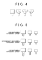
- the holder DB 3 (which is also part the tool holder information storage unit) stores information of a plurality of holders. As shown in FIG. 4 , there are a plurality of types of holders that can respectively hold tools having different edge diameters and different edge shapes, and the holders that can hold the same tool also have multiple shapes. In the holder DB 3, holder numbers are respectively associated with pieces of information relating to the holders.
- the basic tooling DB 4 (which is also part of the basic tooling storage unit according to the example) stores a basic tooling for each of a plurality of machining efficiency groups and for each of different edge diameters of the tools.
- the "basic tooling” is a combination of a tool, a holder and a tool projection length.
- the "machining efficiency” corresponds to a removal volume per unit time. For example, when a given workpiece material (work) is cut by a tool of a given material, tool projection length (L) / tool edge diameter (D) ( ⁇ stiffness) may be used as the machining efficiency.
- the "machining efficiency group” means a group of which the machining efficiency falls within a predetermined range.
- L/D is 5 or below
- L/D is between 5 and 10
- L/D is 10 or above.
- the optimal process determining unit 5 determines an optimal process for forming the product shape from the material shape.
- the optimal process is composed of a plurality of process candidates and the sequence of the process candidates.
- each process candidate includes information of a tooling, including a tool, a holder and a tool projection length, a removal region and an index angle (tool axis position).
- FIG. 6 to FIG. 9 are flowcharts that show an optimal process determining method for determining the optimal process.
- the process determining unit 5 can be, for example, a processor, controller or computer, and the stored data bases (DB) can be stored in an appropriate storage medium, such as in a memory of a computer, and can be part of the same device or separate from the device including the process determining unit 5.
- the determining system can be included in the control system of the machine tool, can be a separate system, or can be a system connected to a machine tool control system. Once the process is determined, the process is carried out by the machine tool to form products shaped using the process.
- the optimal process determining unit 5 reads the product shape from the shape memory unit 1 (S1). Subsequently, the material shape is read from the shape memory unit 1 (S2). Thereafter, tool candidates are read from the tool DB 2 (S3), and holder candidates are read from the holder DB 3 (S4).
- an efficiency-specific process candidate calculation process is executed for a high machining efficiency group (S5).
- a tool edge diameter counter P is set at 1 (S11).
- the counter P of the largest edge diameter for example, ⁇ 18
- the counter P of the second largest edge diameter for example, ⁇ 10
- the counter P of the third largest edge diameter for example, ⁇ 8, is set at 3.
- a basic tooling for the high machining efficiency group is read from the basic tooling DB 4 (S12). Then, the counter i of the index angle of the tool is set at 1 (S13). The index angle corresponds to the tool axis position. Thereafter, the i-th index angle is selected (S14). That is, an actual index angle is selected (as discussed further below). After that, a removable region when the material shape is machined by the basic tooling at the selected index angle is calculated (S15).
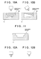
- the removable region at a certain index angle is a hatched region indicated as the removable region in FIG. 10A . That is, the above removable region may be machined without interference of the tool or the holder with a portion of a product shape.
- the removable region is a hatched region indicated as the removable region in FIG. 10B .
- step S16 it is determined whether the index angle counter i is a maximum value (S16).
- the index angle counter i is incremented by 1 (S17) and then the process is repeated from step S14. That is, for each of a plurality of index angles, a removable region of the basic tooling is calculated.
- an index angle, at which a removal volume is maximal among the plurality of removable regions is calculated (S18).
- the index angle of FIG. 10A is compared with the index angle of FIG. 10B , the index angle of FIG. 10A is selected.
- the machined shape is a shape excluding the removable region from the material shape. That is, the machined shape is a shape machined by the basic tooling from the material shape.
- an optimal tooling is calculated (S20).
- the optimal tooling is able to machine the material shape into the machined shape calculated in step S19 without interfering with the machined shape, and has the highest machining efficiency.
- the toolings shown in FIG. 12A and FIG. 12B are able to machine the material shape into the machined shape.
- the tooling shown in FIG. 12B has a short tool projection length and, therefore, has a high machining efficiency.
- the basic tooling is an index tooling for obtaining a predetermined machining efficiency group, and may be different from the optimal tooling selected here or may be the same in some cases.
- an optimal process candidate using the optimal tooling calculated in step S20 is calculated (S21).
- the optimal process candidate is information relating to a plurality of processes, each including an optimal tooling and an optimal index angle.
- step S19 it is determined whether the machined shape calculated in step S19 is updated (S22).
- the process is repeated from step S13. Initially, the machined shape is newly calculated, so, of course, the process is repeated from S13. In the processes from the next step S13 to step S21, the processes are executed while the initially calculated machined shape is regarded as a material shape.
- step S21 when machining is performed using the shape shown in FIG. 11 as a material shape, the hatched region indicated as the removable region in FIG. 13A is a removable region, and the shape shown in FIG. 13B is a machined shape. Then, in step S21, this process is added to the already calculated optimal process candidate. Then, in step S22, it is determined that the machined shape has been updated, so the process is repeated from step S13 again.
- machining is performed using the shape shown in FIG. 13B as a material shape.
- the hatched region indicated as the removable region in FIG. 14A is a removable region
- the shape shown in FIG. 14B is a machined shape.
- the tool edge diameter counter P is a maximum value (S23).
- the tool edge diameter counter P is incremented by 1 (S24) and then the process is repeated from step S12. That is, an optimal process candidate is calculated for each of the plurality of tool edge diameters. Then, when the tool edge diameter counter P reaches the maximum value, the efficiency-specific process candidate calculation process is ended.
- the efficiency-specific process candidate calculation process in the case of the high machining efficiency group is executed in step S5. Subsequently, the efficiency-specific process candidate calculation process in the case of the intermediate machining efficiency group is executed (S6). In addition, after that, the efficiency-specific process candidate calculation process in the case of the low machining efficiency group is executed (S7). In this way, an optimal process candidate is calculated for each of the plurality of different machining efficiency groups and each of the tool edge diameters.
- each of the optimal process candidates correspond to individual processes. That is, each of the individual processes includes information of a tooling, which includes a tool, a holder and a tool projection length, a removal region and an index angle (tool axis position).
- FIG. 8 a further optimal temporary optimal process is calculated on the basis of the integrated temporary optimal process. This process is shown in FIG. 8 .
- the temporary optimal process calculated in step S8 in FIG. 6 is read (S31).
- the process number counter j of the individual process of the temporary optimal process is set at 1 (S32).
- a process that excludes the j-th process from the individual processes is calculated (S33).
- a total removal region when the current temporary optimal process (all the individual processes) is executed is calculated (S34).
- a total removal region when the j-th process excluding process (remaining individual processes excluding the j-th process) is executed is calculated (S34).
- an actual machining time when the current temporary optimal process is executed is calculated (S35).
- an actual machining time when the j-th process excluding process is executed is calculated (S35).
- step S36 it is determined whether the process number counter j is a maximum value (S36).
- the process number counter j is incremented by 1 (S37) and then the process is repeated from step S33. That is, a total removal region and an actual machining time are calculated for each of partially excluded processes that are obtained by sequentially excluding one of the individual processes.
- the temporary optimal process is calculated (updated). That is, when the plurality of optimal process candidates are partially excluded, a partially excluded process of which the total removal region coincides with the total removal region of the temporary optimal process is extracted. That is, among the partially excluded process, a partially excluded process that can remove the total removal region of the current temporary optimal process is extracted. In addition, when a plurality of partially excluded processes are extracted, the process having the shortest actual machining time among the plurality of partially excluded processes is used to update the temporary optimal process (S38).
- step S39 the process is repeated from step S31.
- the temporary optimal process read in step S31 is the temporary optimal process updated in step S38. That is, by repeating steps S31 to S38, individual processes may be excluded so that the total removal region remains unchanged and the actual machining time reduces. By so doing, individual processes having substantially overlapping removal regions are excluded.
- step S38 the temporary optimal process calculated in step S38 is determined as the temporary optimal process (S40). Then, the temporary optimal process calculation process is ended.
- step S9 the temporary optimal process calculation process is executed. Subsequently, an optimal process determining process for determining a further optimal process is executed on the temporary optimal process (S10).
- the optimal process determining process is shown in FIG. 9 .
- the temporary optimal process calculated in step S9 in FIG. 6 is read (S51).
- the combinations are sorted in descending order of similarity (S54). That is, as shown in FIG. 17B , the combination of "the second process and the third process" having the highest similarity is a similarity No. 1, the combination of "the first process and the third process” having the second highest similarity is a similarity No. 2, and the combination of "the first process and the second process” having the third highest similarity is a similarity No. 3.
- an integrated process when the tooling of one of the processes of the similarity No. k is integrated into the tooling of the other one of the processes of the similarity No. k is calculated (S56). That is, an initially calculated integrated process includes an integrated process obtained by integrating the tooling of the second process into the tooling of the third process and an integrated process obtained by integrating the tooling of the third process into the tooling of the second process.
- the optimal process determining unit 5 determines whether the similarity No. k is a maximum value (S59). When the similarity No. k is not a maximum value, the optimal process determining unit 5 adds 1 to the similarity No. k (S60) and then repeats the process from step S56. That is, each of the similarity Nos. is integrated in descending order, and then a total removal region and an actual machining time are calculated for each of the integrated processes that can be integrated.
- an optimal process is determined from among the temporary optimal process and the plurality of integrated processes (S61).
- determination of an optimal process first, only the integrated processes that have the same total removal region as the total removal region of the temporary optimal process are extracted. After that, an optimal process is determined from among the extracted integrated processes and the temporary optimal process.
- a temporary optimal process is shown in the row (a) in the table of FIG. 18
- a process that integrates a tooling "B" of the second process into a tooling "C” of the third process among the extracted integrated processes is shown in the row (b) in the table of FIG. 18
- a process that integrates toolings "A” and "B” of the first process and second process into the tooling "C” of the third process among the extracted integrated processes is shown in the row (c) in the table of FIG. 18 .
- the removal volume of the first process is 300 mm 3
- the machining efficiency (removal volume per unit time) of the tooling "A" of the first process is 30 mm 3 /minute.
- the removal volume of the second process is 60 mm 3
- the machining efficiency of the tooling "B" of the second process is 6 mm 3 /minute.
- the removal volume of the third process is 30 mm 3
- the machining efficiency of the tooling "C" of the third process is 3 mm 3 /minute.
- the actual machining time of the first process is 10 minutes
- the actual machining time of the second process is 10 minutes
- the actual machining time of the third process is 10 minutes. That is, the actual machining time of the temporary optimal process is 30 minutes.
- the first process uses the tooling "A”
- the second process and the third process use the tooling "C”. That is, the integrated process of row (b) of FIG. 18 shows the case where the tooling of the second process is integrated into the tooling of the third process.
- the actual machining time of the first process is 10 minutes
- the actual machining time of the second process is 20 minutes
- the actual machining time of the third process is 10 minutes. That is, the actual machining time of the temporary optimal process is 40 minutes.
- the integrated process of row (c) FIG. 18 shows the case where the toolings of the first and second processes are integrated into the tooling of the third process.
- the actual machining time of the first process is 100 minutes
- the actual machining time of the second process is 20 minutes
- the actual machining time of the third process is 10 minutes. That is, the actual machining time of the temporary optimal process is 130 minutes.
- the unit integration reduction time is a value corresponding to a possession conversion time that is obtained by converting the possession of a tool and a holder by a user of a machine into a time, a tooling preparation time for setting a tool and a holder to the machine or a time consumed for the number of times of tool replacement carried out for machining.
- the unit integration reduction time is 20 minutes.
- the number of integrations is a number by which the toolings of the processes in the temporary optimal process are integrated. That is, the number of integrations in the case of row (b) of FIG. 18 is 1, and the number of integrations in the case of row (c) FIG. 18 is 2.
- the total time of the temporary optimal process shown in row (a) of FIG. 18 is 30 minutes
- the total time of the integrated process shown in row (b) of FIG. 18 is 20 minutes
- the total time of the integrated process shown in row (c) FIG. 18 is 90 minutes.
- the process having the shortest total time is the integrated process shown in row (b) of FIG. 18 .
- the above integrated process is determined as the optimal process.
- the optimal process By determining the optimal process as described above, it is possible to determine a further optimal process.
- the integrated process is determined to be optimal when a time obtained by multiplying the unit integration reduction time by the number of individual processes integrated is longer than the elongated actual machining time. By so doing, it is possible to achieve a reduction in total time at an actual worksite.
- a value of a unit integration reduction time so as to correspond to a possession conversion time, it is possible to reduce the number of tools and the number of holders, possessed by a user of a machine, and it is not necessary to purchase a new tool or a new holder.
- a reduction in the number of tools or the number of holders possessed enables reduction in costs of storage and management.
- a total time may be eventually reduced, and costs may be reduced.
- a value of a unit integration reduction time so as to correspond to a tooling preparation time, it is possible to reduce a total working time with a reduction in tooling preparation time.
- a value of a unit integration reduction time so as to correspond to a time consumed for the number of times of tool replacement, it is possible to reduce a total working time with a reduction in time consumed for the number of times of tool replacement.
- an element of the similarity is any one of the type of tool, the type of holder, a tool projection length and a tool edge diameter, and the similarity coefficient of each element is varied.
- the optimal process determining system intended for a five-axis machine tool that is able to change the index angle (tool axis position) is described.
- the intended five-axis machine tool may be not only a five-axis index machine tool but also a five-axis simultaneous machine tool.
- the five-axis index machine tool carries out machining so that, in a state where at least one of the rotation axes is indexed (fixed), the other rotation axes are moved.
- the five-axis simultaneous machine tool carries out machining while simultaneously controlling travel axes and rotation axes.
- the aspect of the invention may also be applied to an optimal process determining system intended for a machine tool that is able to move along only three orthogonal axes.
- This example eliminates processes regarding the index angle (tool axis position). Specifically, steps S13 to S18 and S22 in the efficiency-specific process candidate calculation process shown in FIG. 7 can be eliminated.
- the other configuration is substantially the same.
- a removable region is calculated using the basic tooling (S15) in the efficiency-specific process candidate calculation process shown in FIG. 7 .
- templates shown in FIG. 19A to FIG. 19C may be used.
- these templates each have a shape that is obtained so that the vertex of a cone shape traces a machined surface of a product shape.
- the basic tooling template, as well as the above described basic tooling is set for each of the plurality of machining efficiency groups.
- the basic tooling templates respectively shown in FIG. 19A, FIG. 19B and FIG. 19C correspond to the high, intermediate and low machining efficiency groups, respectively.
- An optimal process determining system executes a step of calculating a temporary process that includes information of a plurality of individual processes.
- each process includes a tooling including of a tool, a holder, a tool projection length, and a sequence of the plurality of individual processes.
- a similarity between the toolings of two individual processes is calculated.
- a calculation is performed relating to a plurality of integrated processes for which the tooling of one of the individual processes having a high similarity is integrated into the tooling of the other one of the individual processes.
- an optimal process is determined from the plurality of integrated processes on the basis of an actual machining time in each of the integrated processes, a unit integration reduction time reduced as one of the toolings of the individual processes is integrated, and the number of the individual processes integrated.
Landscapes
- Engineering & Computer Science (AREA)
- Manufacturing & Machinery (AREA)
- Physics & Mathematics (AREA)
- Geometry (AREA)
- Human Computer Interaction (AREA)
- General Physics & Mathematics (AREA)
- Automation & Control Theory (AREA)
- Numerical Control (AREA)
- General Factory Administration (AREA)
Applications Claiming Priority (1)
| Application Number | Priority Date | Filing Date | Title |
|---|---|---|---|
| JP2009147831A JP5334701B2 (ja) | 2009-06-22 | 2009-06-22 | 最適工程決定装置および最適工程決定方法 |
Publications (3)
| Publication Number | Publication Date |
|---|---|
| EP2267564A2 true EP2267564A2 (fr) | 2010-12-29 |
| EP2267564A3 EP2267564A3 (fr) | 2014-06-04 |
| EP2267564B1 EP2267564B1 (fr) | 2017-05-31 |
Family
ID=42556642
Family Applications (1)
| Application Number | Title | Priority Date | Filing Date |
|---|---|---|---|
| EP10166643.6A Not-in-force EP2267564B1 (fr) | 2009-06-22 | 2010-06-21 | Système et procédé de détermination de l'intégration de procédé |
Country Status (3)
| Country | Link |
|---|---|
| US (1) | US8428765B2 (fr) |
| EP (1) | EP2267564B1 (fr) |
| JP (1) | JP5334701B2 (fr) |
Cited By (1)
| Publication number | Priority date | Publication date | Assignee | Title |
|---|---|---|---|---|
| EP3098676A1 (fr) * | 2015-05-29 | 2016-11-30 | Kaltenbach GmbH + Co. KG | Procede de substitution d'outil |
Families Citing this family (2)
| Publication number | Priority date | Publication date | Assignee | Title |
|---|---|---|---|---|
| CN106802919B (zh) * | 2016-12-15 | 2021-06-18 | 北京北方车辆集团有限公司 | 一种确定特种车辆板材工艺消耗定额的工艺方法 |
| JP6856606B2 (ja) * | 2018-11-09 | 2021-04-07 | ファナック株式会社 | 実績情報に基づいて設計の支援を行う設計支援装置 |
Citations (1)
| Publication number | Priority date | Publication date | Assignee | Title |
|---|---|---|---|---|
| JPH11235646A (ja) | 1998-02-19 | 1999-08-31 | Toyota Central Res & Dev Lab Inc | 加工工程の決定方法 |
Family Cites Families (15)
| Publication number | Priority date | Publication date | Assignee | Title |
|---|---|---|---|---|
| JPH0698554B2 (ja) * | 1986-09-22 | 1994-12-07 | 豊田工機株式会社 | 数値制御加工装置 |
| IT1247585B (it) * | 1990-02-22 | 1994-12-28 | Jobs Spa | Plotter multifunzione tridimensionale |
| JPH05165842A (ja) * | 1991-12-13 | 1993-07-02 | Toyota Central Res & Dev Lab Inc | 工程時間の見積り装置 |
| JP2798549B2 (ja) * | 1992-03-26 | 1998-09-17 | オークマ株式会社 | 内径加工工具の自動決定方法 |
| US5378091A (en) * | 1992-06-17 | 1995-01-03 | Makino Milling Machine Co., Ltd. | Method and apparatus for machining a workpiece |
| US5796618A (en) * | 1992-10-09 | 1998-08-18 | Omron Corporation | CAD system, method and medium for creating and encoding NC data based before and after workpiece models |
| US5808893A (en) * | 1993-07-28 | 1998-09-15 | Amt Machine Systems, Ltd. | System for adapting an automatic screw machine to achieve computer numeric control |
| US5917726A (en) * | 1993-11-18 | 1999-06-29 | Sensor Adaptive Machines, Inc. | Intelligent machining and manufacturing |
| DE69619789T2 (de) * | 1995-09-28 | 2002-08-29 | THE INSTITUTE OF PHYSICAL & CHEMICAL RESEARCH, WAKO | Methode zum Bearbeiten mit hoher Geschwindigkeit von Matrizen und Ultrahochgeschwindigkeitsfräsmaschine |
| US5933353A (en) * | 1997-09-16 | 1999-08-03 | New Focus, Inc. | Method and apparatus for computer aided machining |
| US6804575B2 (en) * | 2000-10-26 | 2004-10-12 | Citizen Watch Co., Ltd. | Method and device for automatically preparing processing program |
| JP2004284002A (ja) * | 2003-01-31 | 2004-10-14 | Fujitsu Ltd | 加工制御装置 |
| JP3753133B2 (ja) * | 2003-04-25 | 2006-03-08 | マツダ株式会社 | 工作機械のnc加工データ生成方法 |
| CN101489718A (zh) * | 2006-07-18 | 2009-07-22 | 三菱电机株式会社 | 数控装置 |
| JP5142880B2 (ja) | 2008-08-06 | 2013-02-13 | 株式会社豊田中央研究所 | 加工パラメータ最適化装置、加工パラメータ最適化方法およびプログラム |
-
2009
- 2009-06-22 JP JP2009147831A patent/JP5334701B2/ja not_active Expired - Fee Related
-
2010
- 2010-06-21 EP EP10166643.6A patent/EP2267564B1/fr not_active Not-in-force
- 2010-06-22 US US12/820,321 patent/US8428765B2/en not_active Expired - Fee Related
Patent Citations (1)
| Publication number | Priority date | Publication date | Assignee | Title |
|---|---|---|---|---|
| JPH11235646A (ja) | 1998-02-19 | 1999-08-31 | Toyota Central Res & Dev Lab Inc | 加工工程の決定方法 |
Cited By (1)
| Publication number | Priority date | Publication date | Assignee | Title |
|---|---|---|---|---|
| EP3098676A1 (fr) * | 2015-05-29 | 2016-11-30 | Kaltenbach GmbH + Co. KG | Procede de substitution d'outil |
Also Published As
| Publication number | Publication date |
|---|---|
| EP2267564B1 (fr) | 2017-05-31 |
| US8428765B2 (en) | 2013-04-23 |
| JP2011000691A (ja) | 2011-01-06 |
| EP2267564A3 (fr) | 2014-06-04 |
| JP5334701B2 (ja) | 2013-11-06 |
| US20100324714A1 (en) | 2010-12-23 |
Similar Documents
| Publication | Publication Date | Title |
|---|---|---|
| CN101893873B (zh) | 产生用于控制机床上的刀具的控制数据的方法和装置 | |
| KR102364294B1 (ko) | 천공 방법 및 천공기 | |
| JP5689396B2 (ja) | 生産計画装置および生産計画方法 | |
| JP6629410B1 (ja) | Ncプログラム変換処理方法、変換用計算機、及び変換プログラム | |
| US8301293B2 (en) | Process integration determining system and method | |
| EP2267564B1 (fr) | Système et procédé de détermination de l'intégration de procédé | |
| Abdou et al. | TVCAPP, tolerance verification in computer-aided process planning | |
| JP5322881B2 (ja) | 加工シミュレーション装置および最適工程決定装置 | |
| JP5441604B2 (ja) | 最適工程決定装置および最適工程決定方法 | |
| JP2004322265A (ja) | 工作機械のnc加工データ生成方法 | |
| JP5441606B2 (ja) | 最適工程決定装置および最適工程決定方法 | |
| JP4063180B2 (ja) | 金型加工工程決定装置、金型加工工程決定方法、金型加工工程決定プログラム、そのプログラムを記録したコンピュータ読取り可能な記録媒体、ncデータ作成装置、及び工作機械制御装置 | |
| JP5566194B2 (ja) | 最適加工工程決定装置 | |
| CN100371837C (zh) | 数值控制机械 | |
| JP5441605B2 (ja) | 最適工程決定装置とその方法、ncデータの作成支援装置およびその方法 | |
| EP3876050A1 (fr) | Système de support de traitement | |
| JP4748049B2 (ja) | 加工工程の決定方法 | |
| Yamada et al. | Indexing 5-axis machining process design support system shortening die fabrication lead time | |
| KR101348875B1 (ko) | 밀링 커터의 회전체 가공 형상 시뮬레이션 방법 | |
| KR20220064837A (ko) | 원하는 가공물을 얻기 위한 밀링 커터의 회전체 가공 형상 시뮬레이션 기술 | |
| JP2022130952A (ja) | 工具経路生成装置、工具経路生成方法、及び工具経路生成プログラム | |
| Joneja et al. | Greedy tool heuristic for rough milling of complex pockets | |
| KR20110131373A (ko) | 컴퓨터 수치 제어 선반용 절삭 카트리지 및 이를 사용한 가공 방법 |
Legal Events
| Date | Code | Title | Description |
|---|---|---|---|
| PUAI | Public reference made under article 153(3) epc to a published international application that has entered the european phase |
Free format text: ORIGINAL CODE: 0009012 |
|
| AK | Designated contracting states |
Kind code of ref document: A2 Designated state(s): AL AT BE BG CH CY CZ DE DK EE ES FI FR GB GR HR HU IE IS IT LI LT LU LV MC MK MT NL NO PL PT RO SE SI SK SM TR |
|
| AX | Request for extension of the european patent |
Extension state: BA ME RS |
|
| PUAL | Search report despatched |
Free format text: ORIGINAL CODE: 0009013 |
|
| AK | Designated contracting states |
Kind code of ref document: A3 Designated state(s): AL AT BE BG CH CY CZ DE DK EE ES FI FR GB GR HR HU IE IS IT LI LT LU LV MC MK MT NL NO PL PT RO SE SI SK SM TR |
|
| AX | Request for extension of the european patent |
Extension state: BA ME RS |
|
| RIC1 | Information provided on ipc code assigned before grant |
Ipc: G05B 19/4093 20060101AFI20140425BHEP |
|
| 17P | Request for examination filed |
Effective date: 20141127 |
|
| 17Q | First examination report despatched |
Effective date: 20160511 |
|
| GRAP | Despatch of communication of intention to grant a patent |
Free format text: ORIGINAL CODE: EPIDOSNIGR1 |
|
| INTG | Intention to grant announced |
Effective date: 20161220 |
|
| GRAS | Grant fee paid |
Free format text: ORIGINAL CODE: EPIDOSNIGR3 |
|
| GRAA | (expected) grant |
Free format text: ORIGINAL CODE: 0009210 |
|
| AK | Designated contracting states |
Kind code of ref document: B1 Designated state(s): AL AT BE BG CH CY CZ DE DK EE ES FI FR GB GR HR HU IE IS IT LI LT LU LV MC MK MT NL NO PL PT RO SE SI SK SM TR |
|
| REG | Reference to a national code |
Ref country code: CH Ref legal event code: EP Ref country code: GB Ref legal event code: FG4D |
|
| REG | Reference to a national code |
Ref country code: AT Ref legal event code: REF Ref document number: 898023 Country of ref document: AT Kind code of ref document: T Effective date: 20170615 |
|
| REG | Reference to a national code |
Ref country code: IE Ref legal event code: FG4D |
|
| REG | Reference to a national code |
Ref country code: DE Ref legal event code: R096 Ref document number: 602010042621 Country of ref document: DE |
|
| REG | Reference to a national code |
Ref country code: NL Ref legal event code: MP Effective date: 20170531 |
|
| REG | Reference to a national code |
Ref country code: LT Ref legal event code: MG4D |
|
| REG | Reference to a national code |
Ref country code: AT Ref legal event code: MK05 Ref document number: 898023 Country of ref document: AT Kind code of ref document: T Effective date: 20170531 |
|
| PG25 | Lapsed in a contracting state [announced via postgrant information from national office to epo] |
Ref country code: NO Free format text: LAPSE BECAUSE OF FAILURE TO SUBMIT A TRANSLATION OF THE DESCRIPTION OR TO PAY THE FEE WITHIN THE PRESCRIBED TIME-LIMIT Effective date: 20170831 Ref country code: GR Free format text: LAPSE BECAUSE OF FAILURE TO SUBMIT A TRANSLATION OF THE DESCRIPTION OR TO PAY THE FEE WITHIN THE PRESCRIBED TIME-LIMIT Effective date: 20170901 Ref country code: FI Free format text: LAPSE BECAUSE OF FAILURE TO SUBMIT A TRANSLATION OF THE DESCRIPTION OR TO PAY THE FEE WITHIN THE PRESCRIBED TIME-LIMIT Effective date: 20170531 Ref country code: AT Free format text: LAPSE BECAUSE OF FAILURE TO SUBMIT A TRANSLATION OF THE DESCRIPTION OR TO PAY THE FEE WITHIN THE PRESCRIBED TIME-LIMIT Effective date: 20170531 Ref country code: ES Free format text: LAPSE BECAUSE OF FAILURE TO SUBMIT A TRANSLATION OF THE DESCRIPTION OR TO PAY THE FEE WITHIN THE PRESCRIBED TIME-LIMIT Effective date: 20170531 Ref country code: HR Free format text: LAPSE BECAUSE OF FAILURE TO SUBMIT A TRANSLATION OF THE DESCRIPTION OR TO PAY THE FEE WITHIN THE PRESCRIBED TIME-LIMIT Effective date: 20170531 Ref country code: LT Free format text: LAPSE BECAUSE OF FAILURE TO SUBMIT A TRANSLATION OF THE DESCRIPTION OR TO PAY THE FEE WITHIN THE PRESCRIBED TIME-LIMIT Effective date: 20170531 |
|
| PG25 | Lapsed in a contracting state [announced via postgrant information from national office to epo] |
Ref country code: BG Free format text: LAPSE BECAUSE OF FAILURE TO SUBMIT A TRANSLATION OF THE DESCRIPTION OR TO PAY THE FEE WITHIN THE PRESCRIBED TIME-LIMIT Effective date: 20170831 Ref country code: LV Free format text: LAPSE BECAUSE OF FAILURE TO SUBMIT A TRANSLATION OF THE DESCRIPTION OR TO PAY THE FEE WITHIN THE PRESCRIBED TIME-LIMIT Effective date: 20170531 Ref country code: SE Free format text: LAPSE BECAUSE OF FAILURE TO SUBMIT A TRANSLATION OF THE DESCRIPTION OR TO PAY THE FEE WITHIN THE PRESCRIBED TIME-LIMIT Effective date: 20170531 Ref country code: IS Free format text: LAPSE BECAUSE OF FAILURE TO SUBMIT A TRANSLATION OF THE DESCRIPTION OR TO PAY THE FEE WITHIN THE PRESCRIBED TIME-LIMIT Effective date: 20170930 Ref country code: NL Free format text: LAPSE BECAUSE OF FAILURE TO SUBMIT A TRANSLATION OF THE DESCRIPTION OR TO PAY THE FEE WITHIN THE PRESCRIBED TIME-LIMIT Effective date: 20170531 |
|
| PG25 | Lapsed in a contracting state [announced via postgrant information from national office to epo] |
Ref country code: EE Free format text: LAPSE BECAUSE OF FAILURE TO SUBMIT A TRANSLATION OF THE DESCRIPTION OR TO PAY THE FEE WITHIN THE PRESCRIBED TIME-LIMIT Effective date: 20170531 Ref country code: RO Free format text: LAPSE BECAUSE OF FAILURE TO SUBMIT A TRANSLATION OF THE DESCRIPTION OR TO PAY THE FEE WITHIN THE PRESCRIBED TIME-LIMIT Effective date: 20170531 Ref country code: SK Free format text: LAPSE BECAUSE OF FAILURE TO SUBMIT A TRANSLATION OF THE DESCRIPTION OR TO PAY THE FEE WITHIN THE PRESCRIBED TIME-LIMIT Effective date: 20170531 Ref country code: CZ Free format text: LAPSE BECAUSE OF FAILURE TO SUBMIT A TRANSLATION OF THE DESCRIPTION OR TO PAY THE FEE WITHIN THE PRESCRIBED TIME-LIMIT Effective date: 20170531 Ref country code: DK Free format text: LAPSE BECAUSE OF FAILURE TO SUBMIT A TRANSLATION OF THE DESCRIPTION OR TO PAY THE FEE WITHIN THE PRESCRIBED TIME-LIMIT Effective date: 20170531 |
|
| REG | Reference to a national code |
Ref country code: CH Ref legal event code: PL |
|
| PG25 | Lapsed in a contracting state [announced via postgrant information from national office to epo] |
Ref country code: PL Free format text: LAPSE BECAUSE OF FAILURE TO SUBMIT A TRANSLATION OF THE DESCRIPTION OR TO PAY THE FEE WITHIN THE PRESCRIBED TIME-LIMIT Effective date: 20170531 Ref country code: SM Free format text: LAPSE BECAUSE OF FAILURE TO SUBMIT A TRANSLATION OF THE DESCRIPTION OR TO PAY THE FEE WITHIN THE PRESCRIBED TIME-LIMIT Effective date: 20170531 Ref country code: IT Free format text: LAPSE BECAUSE OF FAILURE TO SUBMIT A TRANSLATION OF THE DESCRIPTION OR TO PAY THE FEE WITHIN THE PRESCRIBED TIME-LIMIT Effective date: 20170531 |
|
| REG | Reference to a national code |
Ref country code: DE Ref legal event code: R097 Ref document number: 602010042621 Country of ref document: DE |
|
| REG | Reference to a national code |
Ref country code: IE Ref legal event code: MM4A |
|
| PLBE | No opposition filed within time limit |
Free format text: ORIGINAL CODE: 0009261 |
|
| STAA | Information on the status of an ep patent application or granted ep patent |
Free format text: STATUS: NO OPPOSITION FILED WITHIN TIME LIMIT |
|
| GBPC | Gb: european patent ceased through non-payment of renewal fee |
Effective date: 20170831 |
|
| PG25 | Lapsed in a contracting state [announced via postgrant information from national office to epo] |
Ref country code: IE Free format text: LAPSE BECAUSE OF NON-PAYMENT OF DUE FEES Effective date: 20170621 Ref country code: LI Free format text: LAPSE BECAUSE OF NON-PAYMENT OF DUE FEES Effective date: 20170630 Ref country code: CH Free format text: LAPSE BECAUSE OF NON-PAYMENT OF DUE FEES Effective date: 20170630 Ref country code: LU Free format text: LAPSE BECAUSE OF NON-PAYMENT OF DUE FEES Effective date: 20170621 |
|
| 26N | No opposition filed |
Effective date: 20180301 |
|
| REG | Reference to a national code |
Ref country code: FR Ref legal event code: ST Effective date: 20180417 |
|
| PG25 | Lapsed in a contracting state [announced via postgrant information from national office to epo] |
Ref country code: SI Free format text: LAPSE BECAUSE OF FAILURE TO SUBMIT A TRANSLATION OF THE DESCRIPTION OR TO PAY THE FEE WITHIN THE PRESCRIBED TIME-LIMIT Effective date: 20170531 |
|
| REG | Reference to a national code |
Ref country code: BE Ref legal event code: MM Effective date: 20170630 |
|
| PG25 | Lapsed in a contracting state [announced via postgrant information from national office to epo] |
Ref country code: GB Free format text: LAPSE BECAUSE OF NON-PAYMENT OF DUE FEES Effective date: 20170831 |
|
| PG25 | Lapsed in a contracting state [announced via postgrant information from national office to epo] |
Ref country code: FR Free format text: LAPSE BECAUSE OF NON-PAYMENT OF DUE FEES Effective date: 20170731 Ref country code: BE Free format text: LAPSE BECAUSE OF NON-PAYMENT OF DUE FEES Effective date: 20170630 |
|
| PG25 | Lapsed in a contracting state [announced via postgrant information from national office to epo] |
Ref country code: MT Free format text: LAPSE BECAUSE OF NON-PAYMENT OF DUE FEES Effective date: 20170621 |
|
| PG25 | Lapsed in a contracting state [announced via postgrant information from national office to epo] |
Ref country code: HU Free format text: LAPSE BECAUSE OF FAILURE TO SUBMIT A TRANSLATION OF THE DESCRIPTION OR TO PAY THE FEE WITHIN THE PRESCRIBED TIME-LIMIT; INVALID AB INITIO Effective date: 20100621 Ref country code: MC Free format text: LAPSE BECAUSE OF FAILURE TO SUBMIT A TRANSLATION OF THE DESCRIPTION OR TO PAY THE FEE WITHIN THE PRESCRIBED TIME-LIMIT Effective date: 20170531 |
|
| PG25 | Lapsed in a contracting state [announced via postgrant information from national office to epo] |
Ref country code: CY Free format text: LAPSE BECAUSE OF NON-PAYMENT OF DUE FEES Effective date: 20170531 |
|
| PG25 | Lapsed in a contracting state [announced via postgrant information from national office to epo] |
Ref country code: MK Free format text: LAPSE BECAUSE OF FAILURE TO SUBMIT A TRANSLATION OF THE DESCRIPTION OR TO PAY THE FEE WITHIN THE PRESCRIBED TIME-LIMIT Effective date: 20170531 |
|
| PG25 | Lapsed in a contracting state [announced via postgrant information from national office to epo] |
Ref country code: TR Free format text: LAPSE BECAUSE OF FAILURE TO SUBMIT A TRANSLATION OF THE DESCRIPTION OR TO PAY THE FEE WITHIN THE PRESCRIBED TIME-LIMIT Effective date: 20170531 |
|
| PG25 | Lapsed in a contracting state [announced via postgrant information from national office to epo] |
Ref country code: PT Free format text: LAPSE BECAUSE OF FAILURE TO SUBMIT A TRANSLATION OF THE DESCRIPTION OR TO PAY THE FEE WITHIN THE PRESCRIBED TIME-LIMIT Effective date: 20170531 |
|
| PG25 | Lapsed in a contracting state [announced via postgrant information from national office to epo] |
Ref country code: AL Free format text: LAPSE BECAUSE OF FAILURE TO SUBMIT A TRANSLATION OF THE DESCRIPTION OR TO PAY THE FEE WITHIN THE PRESCRIBED TIME-LIMIT Effective date: 20170531 |
|
| PGFP | Annual fee paid to national office [announced via postgrant information from national office to epo] |
Ref country code: DE Payment date: 20200609 Year of fee payment: 11 |
|
| REG | Reference to a national code |
Ref country code: DE Ref legal event code: R119 Ref document number: 602010042621 Country of ref document: DE |
|
| PG25 | Lapsed in a contracting state [announced via postgrant information from national office to epo] |
Ref country code: DE Free format text: LAPSE BECAUSE OF NON-PAYMENT OF DUE FEES Effective date: 20220101 |