EP2267622A2 - Persönliches Gesundheitsmodul gestützt durch ein Kommunikationsgerät - Google Patents
Persönliches Gesundheitsmodul gestützt durch ein Kommunikationsgerät Download PDFInfo
- Publication number
- EP2267622A2 EP2267622A2 EP10177389A EP10177389A EP2267622A2 EP 2267622 A2 EP2267622 A2 EP 2267622A2 EP 10177389 A EP10177389 A EP 10177389A EP 10177389 A EP10177389 A EP 10177389A EP 2267622 A2 EP2267622 A2 EP 2267622A2
- Authority
- EP
- European Patent Office
- Prior art keywords
- wireless device
- operating condition
- portable communication
- personal health
- communication device
- Prior art date
- Legal status (The legal status is an assumption and is not a legal conclusion. Google has not performed a legal analysis and makes no representation as to the accuracy of the status listed.)
- Granted
Links
Images

Classifications
-
- H—ELECTRICITY
- H04—ELECTRIC COMMUNICATION TECHNIQUE
- H04B—TRANSMISSION
- H04B1/00—Details of transmission systems, not covered by a single one of groups H04B3/00 - H04B13/00; Details of transmission systems not characterised by the medium used for transmission
- H04B1/38—Transceivers, i.e. devices in which transmitter and receiver form a structural unit and in which at least one part is used for functions of transmitting and receiving
- H04B1/3827—Portable transceivers
- H04B1/385—Transceivers carried on the body, e.g. in helmets
-
- G—PHYSICS
- G16—INFORMATION AND COMMUNICATION TECHNOLOGY [ICT] SPECIALLY ADAPTED FOR SPECIFIC APPLICATION FIELDS
- G16H—HEALTHCARE INFORMATICS, i.e. INFORMATION AND COMMUNICATION TECHNOLOGY [ICT] SPECIALLY ADAPTED FOR THE HANDLING OR PROCESSING OF MEDICAL OR HEALTHCARE DATA
- G16H40/00—ICT specially adapted for the management or administration of healthcare resources or facilities; ICT specially adapted for the management or operation of medical equipment or devices
- G16H40/60—ICT specially adapted for the management or administration of healthcare resources or facilities; ICT specially adapted for the management or operation of medical equipment or devices for the operation of medical equipment or devices
- G16H40/67—ICT specially adapted for the management or administration of healthcare resources or facilities; ICT specially adapted for the management or operation of medical equipment or devices for the operation of medical equipment or devices for remote operation
-
- H—ELECTRICITY
- H04—ELECTRIC COMMUNICATION TECHNIQUE
- H04B—TRANSMISSION
- H04B15/00—Suppression or limitation of noise or interference
- H04B15/02—Reducing interference from electric apparatus by means located at or near the interfering apparatus
Definitions
- the technology of the present application applies to personal health module supported by a portable communication device, and more specifically to a personal health module removably mounted to a portable communication device where the portable communication device provides priority to the personal health module and shielding between the portable communication device and personal health module.
- Portable communication devices such as radios and cellular telephones are useful devices in everyday operations.
- Some personal health electronics such as, for example, blood glucose monitors, include radio frequency communication capability to transmit personal health information from the monitor to a central repository of data.
- a personal health module Incorporating the personal health electronics, which for clarity will be generally referred to as a personal health module, into an existing radio frequency communication unit, such as, for example, a conventional cellular telephone, would be desirous except that integrating the functionality of a personal health module, which may include medical equipment, into a generic radio frequency communication unit, such as a cellular telephone, may convert the generic radio frequency communication unit to a medical device subject to the requirements of the food and drug administration for medical devices. Moreover, the radio transmitter or other electronics associated with portable communication device, in some cases, may impact the functionality of the integrated personal health module.
- a conventional portable communication device that is capable of being integrated with a personally health module such that the conventional portable communication device is not considered a medical device and the portable communication device does not interfere or influence the functionality of the personal health module.
- Embodiments disclosed herein address the above stated needs by providing a wireless device that integrates a personal health module with a portable communication device remote station.
- a wireless device has a portable communication device contained in a housing adapted to receive/house a personal health module.
- the portable communication device comprises a control processor that controls the functions of at least the portable communication device.
- the portable communication device includes a user interface connected to the control processor to allow a user to interact with at least the portable communication device and, as explained below, potentially the personal health module.
- a personal health module is mechanically connected and housed with the portable communication device and electrically connected to the portable communication device through an isolation circuit. The isolation circuit electrically isolates the personal health module from the portable communication device.
- Shielding is provided between the portable communication device and the personal health module to inhibit interference with the personal health module.
- the shielding may be electromagnetic shielding to inhibit the radio frequency transmissions from interfering with the personal health module.
- the shielding may be heat shielding to reduce the impact of heat generation from interfering with the personal health module.
- the shielding may be moisture shielding to reduce the impact of moisture from interfering with the personal health module.
- the shielding may be a hermetic to reduce the impact of environmental factors from interfering with the personal health module.
- the shielding may include an antibacterial/microbial component to reduce the impact of biologics from interfering with the personal health module and/or inhibit the spread of infection.
- the shielding may be one or a combination of these and other types of shielding.
- the method includes monitoring a charge on a power source of the wireless device and determining whether the charge for the power source decreases below a first predetermined threshold. If the charge is below the first predetermined threshold, signaling the control processor that the charge for the power source has decreased below the first predetermined threshold; and disabling components of the wireless device to reduce power consumption.
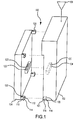
- FIG. 1 is a partially exploded perspective view of a wireless device of an exemplary embodiment
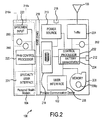
- FIG. 2 is a functional block diagram of a wireless device of an exemplary embodiment
- FIG. 3 is a flow chart diagram illustrating the operational steps of an exemplary embodiment
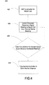
- FIG. 4 is a flow chart diagram illustrating the operational steps of an exemplary embodiment
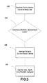
- FIG. 5 is a flow chart diagram illustrating the operational steps of an exemplary embodiment.
- the technology of the present invention will now be described with particular reference to the figures. While the technology is described with particular reference to cellular telephones as the portable communication device, one of ordinary skill in the art of the technology described will now recognize on reading the disclosure herein that the technology of the present application may be implemented in any wireless (or wired) device including, for example, cellular telephones, desktop computers, laptop computers, handheld computers, electronic games, portable digital assistants, MP3 players, DVD players, or the like. Additionally, the personal health modules discussed below may be incorporated into multiple traditionally mobile devices or multiple traditionally non-mobile devices.
- network is used herein to mean one or more conventional or proprietary networks using an appropriate network data transmission protocol. Examples of such networks includes, PSTN, LAN, WAN, WiFi, WiMax, Internet, World Wide Web, Ethernet, other wireless networks, and the like.
- wireless device 100 constructed using the technology of the present application is illustrated.
- wireless device 100 includes a portable communication device 102 and a personal health module 104.
- Wireless device 100 is shown partially exploded for convenience.
- Portable communication device 102 would have at least one radio frequency antenna 106, but may have multiple antennas. Frequently, portable communication device 102 will transmit and receive radio frequency signals over multiple operational frequencies that may require either multiple antennas or a single antenna that operates over the necessary frequencies.
- Portable communication device 102 may consist of any number of devices such as, for example, a wireless computer, a portable digital assistant (such as a BLACKBERRY®, from Research in Motion, Ltd), a cellular telephone, or the like.
- wireless device 100 may be a wired (or a traditionally non-portable) device including a conventional computing device that is connected to a network via a conventional modem, ISP, or the like via a wired connection.
- wireless device 100 may comprise a desktop computer and personal health module 104.
- Wireless device 100 as explained above also has one or more personal health modules (PHMs) 104, although only one PHM 104 is shown for convenience.
- portable communication device 102 has a recess 101 to accommodate PHM 104 such that wireless device 100 houses both portable communication device 102 and PHM 104.
- PHMs 104 may include, by way of non-limiting example, a pulse meter, a blood glucose meter, a oxygen meter, a cardio monitor etc.
- PHMs 104 may be integrated into wireless device 100 or removably connectable to wireless device 100 as a plug-in module or the like.
- PHM 104 shown in figure 1 is removably coupled to wireless device 100 by, for example, a plurality of connections 108, which are shown as snap fit connection 108.
- snap fit connection 108 includes a protrusion 110 extending from PHM 104 with a flared end 112 forming lip 114.
- Protrusion 110 and flared end 112 fit into a corresponding socket 116 in wireless device 100 having a shoulder 118.
- Protrusion 110 should be flexible to allow flared end 112 to pass shoulder 118 such that lip 114 and shoulder 118 abut to mechanically couple or snap fit PHM 104 to portable communication device 102.
- Electrical connection could be by conductive traces 120 on the snap fitting or a separate tab 122 with conductive traces 120 fitting into a slot 124 with corresponding conductive traces 120.
- PHM 104 Electrical and mechanical coupling of PHM 104 to portable communication device 102 should be arranged such that the electrical connection and mechanical connections facilitate connecting a plurality of PHMs 104 to a plurality of portable communication devices 102.
- portable communication device 102 may couple (electrically and mechanically) to a first blood glucose meter PHM 104 and a second cardio meter PHM 104.
- first blood glucose meter PHM 104 may couple (electrically and mechanically) to a cellular telephone portable communication device 102 or a personal computer portable communication device 102.
- Wireless device 100 is described generally as a compact device for mobility, but one of ordinary skill in the art will recognize that wireless device 100 also may be a special processor uniquely designed for the above system, a desktop computer, a laptop computer, a handheld computer, as well as other processors as described above. Moreover, wireless device 100 is not required to be a wireless device, however, it is envisioned that the technology of the present application would be more applicable to wireless, mobile devices.
- Portable communication device 102 includes several components including a control processor 202.
- Control processor 202 controls the major functions of portable communication device 102 including providing computing functionality to process the inputs and/or data required for the operation of portable communication device 102.
- Transmit/receive circuitry 204 is connected to control processor 202 and antenna(s) 106. Transmit/receive circuitry 204 may be one or more actual circuits and may work over various protocols and wavelengths.
- Transmit/receive circuitry 204 functions typical of such components as used in wireless communications, such as modulating signals received from the control processor 202 that are to be transmitted from antenna 106, and demodulating signals received at antenna 106. The demodulated signal is provided to control processor 202.
- Portable communication device 102 includes a user interface 206.
- User interface 206 may comprise a user interface typical of a cellular phone or typical of the wireless device, such as, for example, a keyboard, alphanumeric pad, mouse, track ball, touch screen, voice recognition, microphones, speakers, data ports, input ports, or the like.
- user interface 206 may include features typical of PHM 104. See United States Patent Application Serial Number / , , titled WIRELESS DEVICE WITH PRIVACY SCREEN, filed , and identified by Attorney Docket Number IDF 060948.
- PHM 104 may have a separate user interface.
- Portable communication device 102 includes a memory 208 connected to control processor 202.
- Memory 208 may store data and processing instructions necessary or convenient for operation of portable communication device 102.
- Memory 208 may include volatile and/or nonvolatile memory on any suitable media.
- memory 208 may include a protected portion 208p accessible only on entry of an authentication code, such as, for example, a password or biometric data.
- protected portion 208p may be encrypted.
- Memory 208 may store data relating to information recorded by PHM 104 as well.
- the data may be stored in memory 208 as if memory 208 was a primary store of data, a backup store of data for a memory contained in PHM 104 (not specifically shown), used to check data stored in primary memory, or the like.
- Portable communication device 102 includes a power source 210.
- Power source 210 may be any conventional power source and is typically a battery pack. Power source 210 is connected to a recharge port 218 that is connectable to, for example, a wall socket, a car lighter, or the like.
- Portable communication device 102 also may include a data port 212 (data port 212 may sometimes be referred to as an input port 212 or an output port 212 depending on the context) connected to control processor 202. While not illustrated in figure 2 , portable communication device 102 includes additional components and connections, such as, for example, cables, interfaces, circuit boards, and the like conventional in such devices for operation.
- Portable communication device 102 includes an isolation circuit 214.
- Isolation circuit 214 will be explained further below but is to provide electrical isolation between portable communication device 102 and PHM 104 to inhibit failures or operations of portable communication device 102 from electrically interfering with PHM 104.
- isolation circuit 214 may be contained in PHM 104.
- wireless device 100 combines PHM 104 and portable communication device 102 in a connectable or integrated arrangement.
- PHM 104 may use certain components (such as a memory) of portable communication device 102 or may include separate components.
- PHM 104 may include a PHM control processor 220 to control the major functions of PHM 104 including providing computing functionality to process the inputs and/or data required for the operation of PHM 104.
- PHM control processor 220 would provide the control to identify blood glucose based on the specimen.
- PHMs 104 may be provided with specialty user interfaces 224 as needed. However, PHM 104 may provide and receive data over isolation circuit 214 to portable communication device user interface 206, which includes a display. This would be especially true if PHM 104 only required a user interface compatible with a conventional cellular telephone user interface, for example.
- PHM 104 may contain a separate power supply (not specifically shown), PHM 104 can receive power from power source 210. Power may be supplied over isolation circuit 214. While electrical isolation circuit 214 is helpful, wireless device 100 includes shielding 216, which may reside in portable communication device 102 or PHM 104. Shielding may be, for example, electromagnetic shielding to inhibit radio frequency transmissions from antenna 106 or other RF transmission components from interfering with the PHM 104 or the associated PHM control processor 220. Types of electromagnetic shielding are generally well known in the art and will not be further explained herein. Providing isolation circuit 214 and shielding for shielding 216 segregates portable communication device 102 and PHM 104. Thus, it is envisioned that while certain PHM 104 may be subject to regulation relating to medical devices from the United States Food and Drug Administration, portable communication device 102 may not be subject to the regulations due to the electrical, mechanical, and shielding isolation.
- shielding 216 may include heat shielding as is generally know in the art, such as, fiberglass insulation, phase change material insulations, or the like to regulate the temperature internal to PHM 104. Heat shielding may be necessary in some cases where PHM 104 requires operation in a controlled temperature (additional temperature precautions are described below). Heat shielding may be particularly useful as portable communication device may include electronic components that generate sufficient heat to impact the PHM 104 operation. Shielding 216 also may include sealing components 216s such as a gasket or o-ring to provide a moisture barrier to inhibit moisture from impacting PHM 104. Sealing components may include hermetic sealing components to reduce environmental impacts to PHM 104. Sealing components additionally may include antibacterial or anti microbial components 216c, which also may reduce the spread of infections.
- heat shielding may be necessary in some cases where PHM 104 requires operation in a controlled temperature (additional temperature precautions are described below). Heat shielding may be particularly useful as portable communication device may include electronic components that generate sufficient heat to impact the PHM 104 operation
- control process 202 may have a battery management module 224.
- Battery management module 224 would monitor a charge on power source 210 and shut down functions of portable communication device 102 as charge dropped. For example, if system requirements are at predetermined charge, such as, for example, 50% full charge, only PHM 104 is powered to ensure PHM 104 has sufficient power for a predetermined amount of time.
- control processor 202 would such down all remaining functions of portable communication device 102.
- higher charges such as, for example, 60% of full charge
- only certain functions of portable communication device 102 may be shut down.
- internet functionality may be disabled or a Global Positioning System may be shut down, but cellular communication is maintained.
- battery management module 224 monitors a charge of power source 210, step 302.
- battery management 224 determines whether the monitored charge of power source 210 is above a predetermined threshold, step 304. If charge is above a predetermined threshold, control reverts back to step 302 and steps 302 and 304 are repeated. If charge is below a predetermined threshold, battery management module 224 sends a signal to control processor 202 indicating charge is below the threshold, step 306. Control processor 202 disables or turns off features of portable communication device 102, step 308.
- Control processor 202 could disable all features of portable communication device 102 based on a single comparison.
- battery management module at step 304 may determine whether charge is above a first predetermined threshold, step 304. If charge is below the first predetermined threshold, such as, for example, 75% full charge, battery management module would signal to control processor 202 that charge is below the first threshold, step 306.
- Control processor 202 would correspondingly disable or turn off a first series of functions associated with the first threshold, step 308.
- control processor 202 may disable non-essential functions of remote station portion 102, such as, for example, internet connectivity, but maintain other functions of portable communication device 102, such as, for example, cellular communication.
- Battery management module would continue to monitor charge subsequent to disabling of non-essential functions, step 310.
- Battery management module would determine whether charge drops below a second predetermined threshold, such as, for example, 30% full charge, step 312. If charge is determined not to be below 30% full charge, control returns to step 310 and steps 310 and 312 are repeated. If charge is determined to be below 30% full charge, battery management module signals control processor that charge is below the second predetermined threshold, step 314.
- Control processor would terminate a next series of functions associated with the second predetermined threshold, step 316. For example, control processor may disable a further series of non-essential functions for portable communication device 102 that are more essential than those previously disabled, but still not essential functions. Alternatively, the next series of functions may be the remaining essential functions.
- the number of thresholds and the associated functions that are disabled as power drops below a particular threshold are a matter of design choice and operational conditions.
- PHM 104 has particular operating characteristics that need to be preserved. Operation of PHM 104 may be influenced by operation of electronics such that radio frequency interferences causes malfunction of PHM 104 despite RF shielding installed on the device. Moreover, electronics typically have heat signatures. Many PHMs require biological and/or physiological readings to be taken within certain temperature ranges for accuracy. Thus, a sensor 250 may be provided in device 100. Sensor 250 may sense RF, temperature, moisture, biologics, or the like that may influence readings of PHM 104. As sensor 250 relates to operation of PHM 104, it is envisioned that sensor 250 would be contained in PHM 104, but it may be provided anywhere. Referring now to figure 4 , an exemplary methodology using sensor 250 is provided.
- Sensor 250 may be used to as explained herein to control operating conditions of the wireless device such that the conditions of the wireless device remain within the operational range of PHM 104.
- PHM 104 is activated for a medical use, step 402. It is possible PHM 104 continuously monitors and or continuously reads biological and/or physiological conditions, it this case, step 402 is always potentially satisfied.
- a control processor which can be control processor 220 or 212, receives a signal from sensor 250 relating to a condition that may influence of operation of the medial use, step 404.
- sensor 250 may continually send a signal regardless of whether PHM 104 is activated for medical use as the sensed condition may have a long change time, such as, for example, temperature.
- Sensor 250 may sense, for example, RF strength, temperature, moisture, etc. Based on sensor 250, control processor 220 or 202 determines whether a medical reading would be influenced by the RF strength, temperature, moisture or the like, step 406. In other words, at step 406 the control processor would determine whether the sensed condition is outside an operating range of the associated personal health module. If the sensor comparison indicates the sensed condition may influence the medical reading, appropriate action is taken to eliminate the influence, step 408. Typically, such actions include disabling components of the wireless device (either disabling portions of portable communication device 102 or portions of PHM 104). For example, powering off the radio frequency transmission circuits to reduce the radio frequency signal and powering on such circuits after the medial reading is completed.
- disabling components of the wireless device either disabling portions of portable communication device 102 or portions of PHM 104. For example, powering off the radio frequency transmission circuits to reduce the radio frequency signal and powering on such circuits after the medial reading is completed.
- Another example may include powering off electronics to reduce a heat signature of the device to keep the device temperature within the required temperature range. Still other operations would depend on the operating specifics of the personal health module and the like.
- the appropriate action may be displaying a warning to the user, such as, for example, displaying: "The environmental conditions are causing a high moisture reading that may influence the PHM 104, please relocate to a lower moisture environment if possible.”
- the device may have multiple thresholds to turn off more and more electronics as the critical temperature is reached. Similarly, as temperature (or other sensor information) moves away from the critical temperature, the electronics or the like may be reinitiated.
- the thresholds for turning off and on electronics could be the same or be a hysterias type on/off loop where the electronics are turned off relatively close to the threshold, but not turned on until further from the threshold (or the opposite).
- the electronics can be turned off, the reading taken, and turned back on.
- the electronics may need to be turned off well in advance of the actual medical usage to avoid a situation where the reading cannot be taken due to the excessive temperature.
- the user of wireless device 100 may be using portable communication device 102 for it's intended function, such as, for example, cellular communication, internet access, gaming, music playing or the like.
- PHM 104 may receive or determine important health or medical information, such as, for example, it may detect an unexplained increase in heart rate, it may determine a blood pressure reading window is passing or pending.
- control processor 202 or 220 may provide an interrupt signal alert the user to the medical need.
- Figure 5 shows an exemplary flowchart 500 illustrative of a method interrupting based on medical need or information.
- portable communication device is being used.
- step 504. it is determined whether a medical need exists, is pending, or is passing, step 504. If it is determined a medical need exists, is pending, or is passing, the use of the portable communication device is interrupted, step 506. Optionally, the user could be alerted to the medical need, step 508.
- the interrupts may be preset by a provider, adjusted overtime, user provided, or the like.
- PHM 104 may contain a PHM clock 260.
- PHM clock 260 may operate as any conventional clock and will not be further explained herein.
- PHM 104 may require PHM clock 260 for any number of reasons including, for example, it is needed for one or more medical readings or the like.
- Portable communication device 102 frequently has a system clock 262.
- System clock 262 may be updated and maintained by a signal from a carrier. For example, cellular networks operating under CDMA protocols have precise clocks maintained at, for example, base stations that send clock information over the communication network to, for example, antenna 106 such that system clock 262 is updated by the precise clock (not shown in the figures).
- system clock 262 may be coupled to PHM clock 260 via isolation circuit 214 such that system clock 262 (or more importantly, the precise network clock) is used to set, calibrate, or maintain PHM clock 260 in a conventional manner.
- the clocks 260 and 262 may be coupled via the control processors as shown, directly connected, or the like.
- PHM may have a stand alone memory, referred to herein as PHM memory.
- portable communication device also comprises a memory, such as the aforementioned memory 208, which may include protected memory 208p.
- DSP Digital Signal Processor
- ASIC Application Specific Integrated Circuit
- FPGA Field Programmable Gate Array
- a general purpose processor may be a microprocessor, but in the alternative, the processor may be any conventional processor, controller, microcontroller, or state machine.
- a processor may also be implemented as a combination of computing devices, e.g., a combination of a DSP and a microprocessor, a plurality of microprocessors, one or more microprocessors in conjunction with a DSP core, or any other such configuration.
- a software module may reside in Random Access Memory (RAM), flash memory, Read Only Memory (ROM), Electrically Programmable ROM (EPROM), Electrically Erasable Programmable ROM (EEPROM), registers, hard disk, a removable disk, a CD-ROM, or any other form of storage medium known in the art.
- An exemplary storage medium is coupled to the processor such the processor can read information from, and write information to, the storage medium. In the alternative, the storage medium may be integral to the processor.
- the processor and the storage medium may reside in an ASIC.
Landscapes
- Engineering & Computer Science (AREA)
- Health & Medical Sciences (AREA)
- Computer Networks & Wireless Communication (AREA)
- Signal Processing (AREA)
- Biomedical Technology (AREA)
- General Health & Medical Sciences (AREA)
- General Business, Economics & Management (AREA)
- Epidemiology (AREA)
- Business, Economics & Management (AREA)
- Medical Informatics (AREA)
- Primary Health Care (AREA)
- Public Health (AREA)
- Telephone Function (AREA)
- Mobile Radio Communication Systems (AREA)
- Measuring And Recording Apparatus For Diagnosis (AREA)
- Medical Treatment And Welfare Office Work (AREA)
Applications Claiming Priority (2)
| Application Number | Priority Date | Filing Date | Title |
|---|---|---|---|
| US11/935,644 US8073503B2 (en) | 2007-11-06 | 2007-11-06 | Personal health modules supported by portable communication devices |
| EP08847124A EP2222222B1 (de) | 2007-11-06 | 2008-11-06 | Persönliche gesundheitsmodule, unterstützt von einer tragbaren kommunikationsvorrichtung |
Related Parent Applications (2)
| Application Number | Title | Priority Date | Filing Date |
|---|---|---|---|
| EP08847124A Division EP2222222B1 (de) | 2007-11-06 | 2008-11-06 | Persönliche gesundheitsmodule, unterstützt von einer tragbaren kommunikationsvorrichtung |
| EP08847124.8 Division | 2008-11-06 |
Publications (3)
| Publication Number | Publication Date |
|---|---|
| EP2267622A2 true EP2267622A2 (de) | 2010-12-29 |
| EP2267622A3 EP2267622A3 (de) | 2011-05-18 |
| EP2267622B1 EP2267622B1 (de) | 2012-09-19 |
Family
ID=40527949
Family Applications (2)
| Application Number | Title | Priority Date | Filing Date |
|---|---|---|---|
| EP08847124A Active EP2222222B1 (de) | 2007-11-06 | 2008-11-06 | Persönliche gesundheitsmodule, unterstützt von einer tragbaren kommunikationsvorrichtung |
| EP10177389A Active EP2267622B1 (de) | 2007-11-06 | 2008-11-06 | Persönliches gesundheitsmodul gestützt durch ein kommunikationsgerät |
Family Applications Before (1)
| Application Number | Title | Priority Date | Filing Date |
|---|---|---|---|
| EP08847124A Active EP2222222B1 (de) | 2007-11-06 | 2008-11-06 | Persönliche gesundheitsmodule, unterstützt von einer tragbaren kommunikationsvorrichtung |
Country Status (7)
| Country | Link |
|---|---|
| US (1) | US8073503B2 (de) |
| EP (2) | EP2222222B1 (de) |
| JP (1) | JP5394386B2 (de) |
| KR (1) | KR101143137B1 (de) |
| CN (1) | CN101889283B (de) |
| AT (1) | ATE529039T1 (de) |
| WO (1) | WO2009061940A2 (de) |
Cited By (1)
| Publication number | Priority date | Publication date | Assignee | Title |
|---|---|---|---|---|
| EP2755183A4 (de) * | 2011-09-08 | 2015-04-22 | Lg Electronics Inc | Gesundheitsüberwachungssystem auf videobasis bei einer entfernten gesundheitsdienstlösung und verfahren zur bereitstellung des gesundheitsdienstes |
Families Citing this family (27)
| Publication number | Priority date | Publication date | Assignee | Title |
|---|---|---|---|---|
| US20080088426A1 (en) * | 2006-10-13 | 2008-04-17 | Blair Lima | Baby chime |
| US8626149B2 (en) * | 2007-12-18 | 2014-01-07 | Qualcomm Incorporated | Monitoring and troubleshooting a module associated with a portable communication device |
| WO2010135513A1 (en) * | 2009-05-20 | 2010-11-25 | Sensis Corporation | Corpsman/medic medical assistant system and method |
| US20110105177A1 (en) * | 2009-07-17 | 2011-05-05 | Batiz Rene M | Cell/blood-monitor combination cellphone/blood glucose monitor |
| EP2306351A1 (de) * | 2009-09-23 | 2011-04-06 | EPS Bio Technology Corp. | Gesundheitsmanagementgerät |
| EP2633310A4 (de) | 2010-10-26 | 2016-02-24 | Abbott Diabetes Care Inc | Analytmessvorrichtungen und -systeme sowie komponenten und verfahren in zusammenhang damit |
| US9713440B2 (en) | 2010-12-08 | 2017-07-25 | Abbott Diabetes Care Inc. | Modular analyte measurement systems, modular components thereof and related methods |
| TWI514867B (zh) * | 2011-10-31 | 2015-12-21 | 原相科技股份有限公司 | 低耗能之行車紀錄器 |
| US20130116526A1 (en) | 2011-11-09 | 2013-05-09 | Telcare, Inc. | Handheld Blood Glucose Monitoring Device with Messaging Capability |
| EP2785245A4 (de) * | 2011-12-01 | 2015-08-19 | Modz Oy | Tragbare vorrichtung zur messung von blutproben |
| WO2013137497A1 (ko) * | 2012-03-14 | 2013-09-19 | 엘지전자 주식회사 | 모바일 단말을 이용한 휴대형 진단 시스템 |
| JP6453751B2 (ja) | 2012-05-23 | 2019-01-16 | アイフィノタイプ エルエルシー | 表現型を統合したソーシャル検索データベース及び方法 |
| US9098280B2 (en) * | 2012-12-28 | 2015-08-04 | Intel Corporation | Staged power distribution control |
| TWI571734B (zh) * | 2013-02-05 | 2017-02-21 | 新唐科技股份有限公司 | 電源管理電路與方法以及電腦系統 |
| US9232640B2 (en) * | 2013-03-10 | 2016-01-05 | Qualcomm Incorporated | Thermal isolation in printed circuit board assemblies |
| WO2014178085A2 (en) * | 2013-05-02 | 2014-11-06 | Ashish Jain | A system integrated with communicating device for medical analysis of biological matter |
| CN105432059A (zh) * | 2013-05-15 | 2016-03-23 | 斐拉迪米尔·克兰兹 | 具有增强的功能的移动电话 |
| US10162347B2 (en) * | 2015-04-20 | 2018-12-25 | Lg Electronics Inc. | Mobile terminal and method for controlling the same |
| GB201811494D0 (en) * | 2018-07-13 | 2018-08-29 | Smith & Nephew | Inter-device communications and device control in wound therapy systems |
| US12263294B2 (en) | 2016-09-28 | 2025-04-01 | T.J.Smith And Nephew, Limited | Systems and methods for operating negative pressure wound therapy devices |
| KR20170031675A (ko) | 2017-03-03 | 2017-03-21 | 에스케이플래닛 주식회사 | 사용자 인터페이스 처리 장치, 방법, 컴퓨터 프로그램이 기록된 기록매체 및 단말 장치 |
| US11013488B2 (en) * | 2017-06-23 | 2021-05-25 | Stryker Corporation | Patient monitoring and treatment systems and methods |
| US11413005B2 (en) | 2017-08-14 | 2022-08-16 | Stryker Corporation | Constitutive equation for non-invasive blood pressure measurement systems and methods |
| KR102069093B1 (ko) | 2018-04-17 | 2020-01-22 | (주)블루커뮤니케이션 | 피지컬 소프트웨어 코딩교육장치 |
| KR102069096B1 (ko) | 2018-04-17 | 2020-01-22 | (주)블루커뮤니케이션 | 피지컬 디바이스의 직접적 원격 제어 장치 |
| KR102893427B1 (ko) | 2019-08-14 | 2025-12-02 | 삼성전자주식회사 | 디스플레이 장치 및 그 제어 방법 |
| KR102238411B1 (ko) * | 2019-11-27 | 2021-04-12 | 주식회사 미로 | 탈착 가능한 IoT 모듈 |
Family Cites Families (49)
| Publication number | Priority date | Publication date | Assignee | Title |
|---|---|---|---|---|
| US6241704B1 (en) * | 1901-11-22 | 2001-06-05 | Sims Deltec, Inc. | Drug pump systems and methods |
| JP2853233B2 (ja) * | 1990-02-06 | 1999-02-03 | オムロン株式会社 | 血圧記録装置 |
| JPH057557A (ja) * | 1991-07-02 | 1993-01-19 | Nec Corp | トレーニングモニタ |
| US5944659A (en) * | 1995-11-13 | 1999-08-31 | Vitalcom Inc. | Architecture for TDMA medical telemetry system |
| FI960636A7 (fi) * | 1996-02-12 | 1997-08-13 | Nokia Corp | Menetelmä potilaan terveydentilan valvomiseksi |
| JP3036954U (ja) * | 1996-09-21 | 1997-05-06 | 株式会社ジー・エム・エス | 携帯用心拍間隔記録装置 |
| FI111217B (fi) | 1997-06-19 | 2003-06-30 | Nokia Corp | Laite näytteiden ottamiseksi |
| AUPO826597A0 (en) | 1997-07-25 | 1997-08-21 | Platt, Harry Louis | Cardiac patient remote monitoring apparatus |
| FI107080B (fi) | 1997-10-27 | 2001-05-31 | Nokia Mobile Phones Ltd | Mittauslaite |
| US6008980A (en) * | 1997-11-13 | 1999-12-28 | Maxwell Energy Products, Inc. | Hermetically sealed EMI feedthrough filter capacitor for human implant and other applications |
| US6643903B2 (en) * | 1997-11-13 | 2003-11-11 | Greatbatch-Sierra, Inc. | Process for manufacturing an EMI filter feedthrough terminal assembly |
| JP4214589B2 (ja) * | 1998-12-25 | 2009-01-28 | パナソニック株式会社 | 端末網制御装置 |
| JP2001186251A (ja) * | 1999-12-27 | 2001-07-06 | Nec Corp | 携帯情報端末装置及び電源電力供給制御方法 |
| JP2001197197A (ja) * | 2000-01-17 | 2001-07-19 | Funai Electric Co Ltd | 携帯型電話機、及び、記憶媒体 |
| JP2002090326A (ja) * | 2000-09-20 | 2002-03-27 | Tdk Corp | 携帯用電子機器 |
| JP2002150229A (ja) * | 2000-11-15 | 2002-05-24 | Dainippon Printing Co Ltd | 携帯電話機用icカードリーダー・ライタコネクタ |
| JP2002222263A (ja) * | 2001-01-24 | 2002-08-09 | Iscg Kk | 健康の自己管理用携帯端末、及び健康の自己管理支援システム |
| US8195295B2 (en) * | 2008-03-20 | 2012-06-05 | Greatbatch Ltd. | Shielded three-terminal flat-through EMI/energy dissipating filter |
| JP2002325122A (ja) * | 2001-04-25 | 2002-11-08 | Sony Corp | 通信用モジュールおよび該通信用モジュールを備えた通信装置 |
| JP2002367717A (ja) * | 2001-06-11 | 2002-12-20 | Sony Corp | 電気的接続装置および電気的接続装置を有する電子機器 |
| US6949706B2 (en) * | 2001-09-28 | 2005-09-27 | Siemens Information And Communication Mobile, Llc | Radio frequency shield for electronic equipment |
| JP2003168178A (ja) * | 2001-12-04 | 2003-06-13 | Nec Corp | 携帯通信端末および監視制御システム |
| MXPA04008786A (es) * | 2002-03-12 | 2005-06-17 | Era Ct Pty Ltd | Telefono movil multifuncional para diagnosis medica y rehabilitacion. |
| KR100472092B1 (ko) | 2002-05-14 | 2005-03-08 | 주식회사 헬스피아 | 이동통신단말기를 이용한 혈당측정장치 및 그 측정치를인터넷상의 서버에 전송하는 방법. |
| KR20040032451A (ko) | 2002-10-09 | 2004-04-17 | 삼성전자주식회사 | 생체신호 기반의 건강 관리 기능을 갖는 모바일 기기 및이를 이용한 건강 관리 방법 |
| WO2004038943A1 (en) | 2002-10-24 | 2004-05-06 | Healthpia Co., Ltd. | Battery pack of a mobile communication terminal and connector for connecting the battery pack with the terminal |
| TWI304321B (en) * | 2002-12-27 | 2008-12-11 | Toray Industries | Layered products, electromagnetic wave shielding molded articles and method for production thereof |
| US7326862B2 (en) * | 2003-02-13 | 2008-02-05 | Parker-Hannifin Corporation | Combination metal and plastic EMI shield |
| US7005573B2 (en) * | 2003-02-13 | 2006-02-28 | Parker-Hannifin Corporation | Composite EMI shield |
| US7031745B2 (en) | 2003-05-12 | 2006-04-18 | Shen Ein-Yiao | Cellular phone combined physiological condition examination and processing device |
| KR100502713B1 (ko) | 2003-05-29 | 2005-07-20 | 주식회사 헬스피아 | 자가 진단용 배터리 팩과 자가 진단 시스템 |
| CN1565382A (zh) * | 2003-06-30 | 2005-01-19 | 魏倩 | 传送心电信号的方法 |
| KR20030091070A (ko) * | 2003-10-24 | 2003-12-01 | 송호진 | 건강상태 측정기가 결합된 이동통신 단말기와 그를 이용한건강정보 제공 시스템 |
| WO2005079664A1 (en) | 2004-02-19 | 2005-09-01 | Edward Henry Mathews | Blood glucose monitor for mobile communication device |
| KR100591239B1 (ko) * | 2004-04-26 | 2006-06-19 | 한국전자통신연구원 | 이동통신 단말기용 건강상태 측정장치 및 그 정보관리방법 |
| US7765001B2 (en) * | 2005-08-31 | 2010-07-27 | Ebr Systems, Inc. | Methods and systems for heart failure prevention and treatments using ultrasound and leadless implantable devices |
| JP2006005473A (ja) * | 2004-06-15 | 2006-01-05 | Sony Corp | 電話機用スイッチ装置及び電話機の4端子モジュラーケーブルの接続パターン識別方法 |
| JP2006102388A (ja) | 2004-10-08 | 2006-04-20 | Matsushita Electric Works Ltd | 携帯端末装置 |
| EP1656883A1 (de) * | 2004-11-10 | 2006-05-17 | Universite Libre De Bruxelles | Tragbares Gerät zur Messung eines EMG-Signals |
| DE102005006024A1 (de) | 2005-02-08 | 2006-10-05 | Deutsche Telekom Ag | Vorrichtung zur Überwachung von Vitalwerten Gebrechlicher |
| IL166804A (en) * | 2005-02-10 | 2012-08-30 | Cellvine Ltd | Apparatus and method for traffic load balancing in wireless networks |
| DE102005028203B4 (de) | 2005-03-03 | 2010-11-11 | Diabetes.Online Ag | Mobiltelefon mit eingebautem Messgerät |
| EP1859533B1 (de) | 2005-03-03 | 2009-07-15 | Diabetes.Online AG | Mobiltelefon mit eingebautem messgerät |
| EP1722310A1 (de) | 2005-04-12 | 2006-11-15 | Roche Diagnostics GmbH | Herunterladen von medizinische Software zum Handy |
| JP2007043422A (ja) * | 2005-08-02 | 2007-02-15 | Toshiba Corp | 携帯通信端末 |
| US8224034B2 (en) * | 2006-02-02 | 2012-07-17 | NL Giken Incorporated | Biometrics system, biologic information storage, and portable device |
| US7490266B2 (en) * | 2006-02-13 | 2009-02-10 | Freescale Semiconductor, Inc. | Integrated circuit and processing system with improved power source monitoring and methods for use therewith |
| US7611358B2 (en) * | 2006-09-08 | 2009-11-03 | Siemens Energy & Automation, Inc. | Method of coupling circuit board connectors |
| US7986921B2 (en) * | 2007-03-06 | 2011-07-26 | Qualcomm Incorporated | Wireless device with privacy screen |
-
2007
- 2007-11-06 US US11/935,644 patent/US8073503B2/en active Active
-
2008
- 2008-11-06 EP EP08847124A patent/EP2222222B1/de active Active
- 2008-11-06 EP EP10177389A patent/EP2267622B1/de active Active
- 2008-11-06 KR KR1020107012476A patent/KR101143137B1/ko active Active
- 2008-11-06 AT AT08847124T patent/ATE529039T1/de not_active IP Right Cessation
- 2008-11-06 CN CN2008801193451A patent/CN101889283B/zh active Active
- 2008-11-06 WO PCT/US2008/082665 patent/WO2009061940A2/en not_active Ceased
- 2008-11-06 JP JP2010533247A patent/JP5394386B2/ja not_active Expired - Fee Related
Non-Patent Citations (1)
| Title |
|---|
| None |
Cited By (1)
| Publication number | Priority date | Publication date | Assignee | Title |
|---|---|---|---|---|
| EP2755183A4 (de) * | 2011-09-08 | 2015-04-22 | Lg Electronics Inc | Gesundheitsüberwachungssystem auf videobasis bei einer entfernten gesundheitsdienstlösung und verfahren zur bereitstellung des gesundheitsdienstes |
Also Published As
| Publication number | Publication date |
|---|---|
| US20090117861A1 (en) | 2009-05-07 |
| EP2222222A2 (de) | 2010-09-01 |
| WO2009061940A3 (en) | 2009-11-05 |
| EP2267622A3 (de) | 2011-05-18 |
| US8073503B2 (en) | 2011-12-06 |
| JP2011504013A (ja) | 2011-01-27 |
| ATE529039T1 (de) | 2011-11-15 |
| WO2009061940A2 (en) | 2009-05-14 |
| KR101143137B1 (ko) | 2012-05-08 |
| EP2222222B1 (de) | 2011-10-19 |
| CN101889283A (zh) | 2010-11-17 |
| JP5394386B2 (ja) | 2014-01-22 |
| CN101889283B (zh) | 2013-03-27 |
| KR20100075683A (ko) | 2010-07-02 |
| EP2267622B1 (de) | 2012-09-19 |
Similar Documents
| Publication | Publication Date | Title |
|---|---|---|
| EP2267622B1 (de) | Persönliches gesundheitsmodul gestützt durch ein kommunikationsgerät | |
| US11789008B2 (en) | Systems, devices, and methods for wireless communications in analyte monitoring systems | |
| CN108370084B (zh) | 用于多上下文设备的动态天线功率控制 | |
| CN101926156B (zh) | 对与便携式通信装置相关联的模块进行监视和故障查找 | |
| JP4965650B2 (ja) | 電子装置の電力管理システム | |
| EP2843847B1 (de) | Vorrichtung, Verfahren und System zum effizienten Betrieb einer Nahfeldkommunikationsvorrichtung | |
| EP2887489A1 (de) | Drahtloses Laden und Kommunikation | |
| US20120250539A1 (en) | Techniques to determine user presence | |
| US7508169B2 (en) | System and method for power consumption management during operation of an electronic device | |
| CN108200493A (zh) | 耳机组件、耳机的功能控制方法及装置 | |
| EP2975490B1 (de) | Verfahren und vorrichtung für leistungsverwaltung | |
| US20240144755A1 (en) | Access control electronics for wireless locks | |
| EP3360389B1 (de) | Protokollübersetzungsvorrichtung | |
| US20120250745A1 (en) | System and method for rf interference mitigation through memory clock frequency control | |
| CN101454987A (zh) | 用于降低可拆卸卡的功率消耗的方法及其移动通信终端 | |
| US8670800B2 (en) | Removable baseband chipset | |
| CN116321056B (zh) | 一种车载nfc控制方法、控制系统、车载nfc模块和汽车 | |
| JP5034721B2 (ja) | 記憶装置 | |
| JP2002185605A (ja) | 携帯電話のバッテリーパック | |
| KR20060029561A (ko) | 휴대 기기용 분실방지 시스템 |
Legal Events
| Date | Code | Title | Description |
|---|---|---|---|
| PUAI | Public reference made under article 153(3) epc to a published international application that has entered the european phase |
Free format text: ORIGINAL CODE: 0009012 |
|
| AC | Divisional application: reference to earlier application |
Ref document number: 2222222 Country of ref document: EP Kind code of ref document: P |
|
| AK | Designated contracting states |
Kind code of ref document: A2 Designated state(s): AT BE BG CH CY CZ DE DK EE ES FI FR GB GR HR HU IE IS IT LI LT LU LV MC MT NL NO PL PT RO SE SI SK TR |
|
| PUAL | Search report despatched |
Free format text: ORIGINAL CODE: 0009013 |
|
| AK | Designated contracting states |
Kind code of ref document: A3 Designated state(s): AT BE BG CH CY CZ DE DK EE ES FI FR GB GR HR HU IE IS IT LI LT LU LV MC MT NL NO PL PT RO SE SI SK TR |
|
| RIC1 | Information provided on ipc code assigned before grant |
Ipc: H04B 15/02 20060101ALI20110413BHEP Ipc: G06F 19/00 20110101AFI20101105BHEP |
|
| 17P | Request for examination filed |
Effective date: 20111024 |
|
| GRAP | Despatch of communication of intention to grant a patent |
Free format text: ORIGINAL CODE: EPIDOSNIGR1 |
|
| RTI1 | Title (correction) |
Free format text: PERSONAL HEALTH MODULES SUPPORTED BY PORTABLE COMMUNICATION DEVICE |
|
| GRAS | Grant fee paid |
Free format text: ORIGINAL CODE: EPIDOSNIGR3 |
|
| GRAA | (expected) grant |
Free format text: ORIGINAL CODE: 0009210 |
|
| AC | Divisional application: reference to earlier application |
Ref document number: 2222222 Country of ref document: EP Kind code of ref document: P |
|
| AK | Designated contracting states |
Kind code of ref document: B1 Designated state(s): AT BE BG CH CY CZ DE DK EE ES FI FR GB GR HR HU IE IS IT LI LT LU LV MC MT NL NO PL PT RO SE SI SK TR |
|
| REG | Reference to a national code |
Ref country code: GB Ref legal event code: FG4D |
|
| REG | Reference to a national code |
Ref country code: CH Ref legal event code: EP |
|
| REG | Reference to a national code |
Ref country code: IE Ref legal event code: FG4D |
|
| REG | Reference to a national code |
Ref country code: AT Ref legal event code: REF Ref document number: 576330 Country of ref document: AT Kind code of ref document: T Effective date: 20121015 |
|
| REG | Reference to a national code |
Ref country code: DE Ref legal event code: R096 Ref document number: 602008018920 Country of ref document: DE Effective date: 20121115 |
|
| PG25 | Lapsed in a contracting state [announced via postgrant information from national office to epo] |
Ref country code: NO Free format text: LAPSE BECAUSE OF FAILURE TO SUBMIT A TRANSLATION OF THE DESCRIPTION OR TO PAY THE FEE WITHIN THE PRESCRIBED TIME-LIMIT Effective date: 20121219 Ref country code: FI Free format text: LAPSE BECAUSE OF FAILURE TO SUBMIT A TRANSLATION OF THE DESCRIPTION OR TO PAY THE FEE WITHIN THE PRESCRIBED TIME-LIMIT Effective date: 20120919 Ref country code: LT Free format text: LAPSE BECAUSE OF FAILURE TO SUBMIT A TRANSLATION OF THE DESCRIPTION OR TO PAY THE FEE WITHIN THE PRESCRIBED TIME-LIMIT Effective date: 20120919 Ref country code: HR Free format text: LAPSE BECAUSE OF FAILURE TO SUBMIT A TRANSLATION OF THE DESCRIPTION OR TO PAY THE FEE WITHIN THE PRESCRIBED TIME-LIMIT Effective date: 20120919 |
|
| REG | Reference to a national code |
Ref country code: NL Ref legal event code: VDEP Effective date: 20120919 |
|
| REG | Reference to a national code |
Ref country code: AT Ref legal event code: MK05 Ref document number: 576330 Country of ref document: AT Kind code of ref document: T Effective date: 20120919 |
|
| REG | Reference to a national code |
Ref country code: LT Ref legal event code: MG4D Effective date: 20120919 |
|
| PG25 | Lapsed in a contracting state [announced via postgrant information from national office to epo] |
Ref country code: SI Free format text: LAPSE BECAUSE OF FAILURE TO SUBMIT A TRANSLATION OF THE DESCRIPTION OR TO PAY THE FEE WITHIN THE PRESCRIBED TIME-LIMIT Effective date: 20120919 Ref country code: LV Free format text: LAPSE BECAUSE OF FAILURE TO SUBMIT A TRANSLATION OF THE DESCRIPTION OR TO PAY THE FEE WITHIN THE PRESCRIBED TIME-LIMIT Effective date: 20120919 Ref country code: SE Free format text: LAPSE BECAUSE OF FAILURE TO SUBMIT A TRANSLATION OF THE DESCRIPTION OR TO PAY THE FEE WITHIN THE PRESCRIBED TIME-LIMIT Effective date: 20120919 Ref country code: GR Free format text: LAPSE BECAUSE OF FAILURE TO SUBMIT A TRANSLATION OF THE DESCRIPTION OR TO PAY THE FEE WITHIN THE PRESCRIBED TIME-LIMIT Effective date: 20121220 |
|
| PG25 | Lapsed in a contracting state [announced via postgrant information from national office to epo] |
Ref country code: BE Free format text: LAPSE BECAUSE OF FAILURE TO SUBMIT A TRANSLATION OF THE DESCRIPTION OR TO PAY THE FEE WITHIN THE PRESCRIBED TIME-LIMIT Effective date: 20120919 Ref country code: ES Free format text: LAPSE BECAUSE OF FAILURE TO SUBMIT A TRANSLATION OF THE DESCRIPTION OR TO PAY THE FEE WITHIN THE PRESCRIBED TIME-LIMIT Effective date: 20121230 Ref country code: EE Free format text: LAPSE BECAUSE OF FAILURE TO SUBMIT A TRANSLATION OF THE DESCRIPTION OR TO PAY THE FEE WITHIN THE PRESCRIBED TIME-LIMIT Effective date: 20120919 Ref country code: NL Free format text: LAPSE BECAUSE OF FAILURE TO SUBMIT A TRANSLATION OF THE DESCRIPTION OR TO PAY THE FEE WITHIN THE PRESCRIBED TIME-LIMIT Effective date: 20120919 Ref country code: IS Free format text: LAPSE BECAUSE OF FAILURE TO SUBMIT A TRANSLATION OF THE DESCRIPTION OR TO PAY THE FEE WITHIN THE PRESCRIBED TIME-LIMIT Effective date: 20130119 Ref country code: CZ Free format text: LAPSE BECAUSE OF FAILURE TO SUBMIT A TRANSLATION OF THE DESCRIPTION OR TO PAY THE FEE WITHIN THE PRESCRIBED TIME-LIMIT Effective date: 20120919 Ref country code: RO Free format text: LAPSE BECAUSE OF FAILURE TO SUBMIT A TRANSLATION OF THE DESCRIPTION OR TO PAY THE FEE WITHIN THE PRESCRIBED TIME-LIMIT Effective date: 20120919 |
|
| PG25 | Lapsed in a contracting state [announced via postgrant information from national office to epo] |
Ref country code: SK Free format text: LAPSE BECAUSE OF FAILURE TO SUBMIT A TRANSLATION OF THE DESCRIPTION OR TO PAY THE FEE WITHIN THE PRESCRIBED TIME-LIMIT Effective date: 20120919 Ref country code: PT Free format text: LAPSE BECAUSE OF FAILURE TO SUBMIT A TRANSLATION OF THE DESCRIPTION OR TO PAY THE FEE WITHIN THE PRESCRIBED TIME-LIMIT Effective date: 20130121 Ref country code: PL Free format text: LAPSE BECAUSE OF FAILURE TO SUBMIT A TRANSLATION OF THE DESCRIPTION OR TO PAY THE FEE WITHIN THE PRESCRIBED TIME-LIMIT Effective date: 20120919 |
|
| PG25 | Lapsed in a contracting state [announced via postgrant information from national office to epo] |
Ref country code: AT Free format text: LAPSE BECAUSE OF FAILURE TO SUBMIT A TRANSLATION OF THE DESCRIPTION OR TO PAY THE FEE WITHIN THE PRESCRIBED TIME-LIMIT Effective date: 20120919 |
|
| REG | Reference to a national code |
Ref country code: CH Ref legal event code: PL |
|
| PLBE | No opposition filed within time limit |
Free format text: ORIGINAL CODE: 0009261 |
|
| STAA | Information on the status of an ep patent application or granted ep patent |
Free format text: STATUS: NO OPPOSITION FILED WITHIN TIME LIMIT |
|
| PG25 | Lapsed in a contracting state [announced via postgrant information from national office to epo] |
Ref country code: BG Free format text: LAPSE BECAUSE OF FAILURE TO SUBMIT A TRANSLATION OF THE DESCRIPTION OR TO PAY THE FEE WITHIN THE PRESCRIBED TIME-LIMIT Effective date: 20121219 Ref country code: DK Free format text: LAPSE BECAUSE OF FAILURE TO SUBMIT A TRANSLATION OF THE DESCRIPTION OR TO PAY THE FEE WITHIN THE PRESCRIBED TIME-LIMIT Effective date: 20120919 Ref country code: LI Free format text: LAPSE BECAUSE OF NON-PAYMENT OF DUE FEES Effective date: 20121130 Ref country code: CH Free format text: LAPSE BECAUSE OF NON-PAYMENT OF DUE FEES Effective date: 20121130 |
|
| REG | Reference to a national code |
Ref country code: IE Ref legal event code: MM4A |
|
| REG | Reference to a national code |
Ref country code: FR Ref legal event code: ST Effective date: 20130731 |
|
| 26N | No opposition filed |
Effective date: 20130620 |
|
| PG25 | Lapsed in a contracting state [announced via postgrant information from national office to epo] |
Ref country code: IT Free format text: LAPSE BECAUSE OF FAILURE TO SUBMIT A TRANSLATION OF THE DESCRIPTION OR TO PAY THE FEE WITHIN THE PRESCRIBED TIME-LIMIT Effective date: 20120919 |
|
| REG | Reference to a national code |
Ref country code: DE Ref legal event code: R097 Ref document number: 602008018920 Country of ref document: DE Effective date: 20130620 |
|
| PG25 | Lapsed in a contracting state [announced via postgrant information from national office to epo] |
Ref country code: IE Free format text: LAPSE BECAUSE OF NON-PAYMENT OF DUE FEES Effective date: 20121106 |
|
| PG25 | Lapsed in a contracting state [announced via postgrant information from national office to epo] |
Ref country code: CY Free format text: LAPSE BECAUSE OF FAILURE TO SUBMIT A TRANSLATION OF THE DESCRIPTION OR TO PAY THE FEE WITHIN THE PRESCRIBED TIME-LIMIT Effective date: 20120919 Ref country code: MT Free format text: LAPSE BECAUSE OF FAILURE TO SUBMIT A TRANSLATION OF THE DESCRIPTION OR TO PAY THE FEE WITHIN THE PRESCRIBED TIME-LIMIT Effective date: 20120919 Ref country code: FR Free format text: LAPSE BECAUSE OF NON-PAYMENT OF DUE FEES Effective date: 20121130 |
|
| PG25 | Lapsed in a contracting state [announced via postgrant information from national office to epo] |
Ref country code: MC Free format text: LAPSE BECAUSE OF NON-PAYMENT OF DUE FEES Effective date: 20121130 Ref country code: TR Free format text: LAPSE BECAUSE OF FAILURE TO SUBMIT A TRANSLATION OF THE DESCRIPTION OR TO PAY THE FEE WITHIN THE PRESCRIBED TIME-LIMIT Effective date: 20120919 |
|
| PG25 | Lapsed in a contracting state [announced via postgrant information from national office to epo] |
Ref country code: LU Free format text: LAPSE BECAUSE OF NON-PAYMENT OF DUE FEES Effective date: 20121106 |
|
| PG25 | Lapsed in a contracting state [announced via postgrant information from national office to epo] |
Ref country code: HU Free format text: LAPSE BECAUSE OF FAILURE TO SUBMIT A TRANSLATION OF THE DESCRIPTION OR TO PAY THE FEE WITHIN THE PRESCRIBED TIME-LIMIT Effective date: 20081106 |
|
| REG | Reference to a national code |
Ref country code: DE Ref legal event code: R079 Ref document number: 602008018920 Country of ref document: DE Free format text: PREVIOUS MAIN CLASS: G06F0019000000 Ipc: G16Z0099000000 |
|
| PGFP | Annual fee paid to national office [announced via postgrant information from national office to epo] |
Ref country code: DE Payment date: 20251013 Year of fee payment: 18 |
|
| PGFP | Annual fee paid to national office [announced via postgrant information from national office to epo] |
Ref country code: GB Payment date: 20251009 Year of fee payment: 18 |