EP2267792A1 - Solarzellenmodul - Google Patents
Solarzellenmodul Download PDFInfo
- Publication number
- EP2267792A1 EP2267792A1 EP09725859A EP09725859A EP2267792A1 EP 2267792 A1 EP2267792 A1 EP 2267792A1 EP 09725859 A EP09725859 A EP 09725859A EP 09725859 A EP09725859 A EP 09725859A EP 2267792 A1 EP2267792 A1 EP 2267792A1
- Authority
- EP
- European Patent Office
- Prior art keywords
- solar cell
- frame
- hollow member
- space
- cell module
- Prior art date
- Legal status (The legal status is an assumption and is not a legal conclusion. Google has not performed a legal analysis and makes no representation as to the accuracy of the status listed.)
- Granted
Links
Images




Classifications
-
- F—MECHANICAL ENGINEERING; LIGHTING; HEATING; WEAPONS; BLASTING
- F24—HEATING; RANGES; VENTILATING
- F24S—SOLAR HEAT COLLECTORS; SOLAR HEAT SYSTEMS
- F24S25/00—Arrangement of stationary mountings or supports for solar heat collector modules
- F24S25/20—Peripheral frames for modules
-
- F—MECHANICAL ENGINEERING; LIGHTING; HEATING; WEAPONS; BLASTING
- F24—HEATING; RANGES; VENTILATING
- F24S—SOLAR HEAT COLLECTORS; SOLAR HEAT SYSTEMS
- F24S40/00—Safety or protection arrangements of solar heat collectors; Preventing malfunction of solar heat collectors
- F24S40/40—Preventing corrosion; Protecting against dirt or contamination
- F24S40/44—Draining rainwater or condensation
-
- H—ELECTRICITY
- H02—GENERATION; CONVERSION OR DISTRIBUTION OF ELECTRIC POWER
- H02S—GENERATION OF ELECTRIC POWER BY CONVERSION OF INFRARED RADIATION, VISIBLE LIGHT OR ULTRAVIOLET LIGHT, e.g. USING PHOTOVOLTAIC [PV] MODULES
- H02S20/00—Supporting structures for PV modules
-
- H—ELECTRICITY
- H02—GENERATION; CONVERSION OR DISTRIBUTION OF ELECTRIC POWER
- H02S—GENERATION OF ELECTRIC POWER BY CONVERSION OF INFRARED RADIATION, VISIBLE LIGHT OR ULTRAVIOLET LIGHT, e.g. USING PHOTOVOLTAIC [PV] MODULES
- H02S30/00—Structural details of PV modules other than those related to light conversion
- H02S30/10—Frame structures
-
- Y—GENERAL TAGGING OF NEW TECHNOLOGICAL DEVELOPMENTS; GENERAL TAGGING OF CROSS-SECTIONAL TECHNOLOGIES SPANNING OVER SEVERAL SECTIONS OF THE IPC; TECHNICAL SUBJECTS COVERED BY FORMER USPC CROSS-REFERENCE ART COLLECTIONS [XRACs] AND DIGESTS
- Y02—TECHNOLOGIES OR APPLICATIONS FOR MITIGATION OR ADAPTATION AGAINST CLIMATE CHANGE
- Y02E—REDUCTION OF GREENHOUSE GAS [GHG] EMISSIONS, RELATED TO ENERGY GENERATION, TRANSMISSION OR DISTRIBUTION
- Y02E10/00—Energy generation through renewable energy sources
- Y02E10/40—Solar thermal energy, e.g. solar towers
- Y02E10/47—Mountings or tracking
-
- Y—GENERAL TAGGING OF NEW TECHNOLOGICAL DEVELOPMENTS; GENERAL TAGGING OF CROSS-SECTIONAL TECHNOLOGIES SPANNING OVER SEVERAL SECTIONS OF THE IPC; TECHNICAL SUBJECTS COVERED BY FORMER USPC CROSS-REFERENCE ART COLLECTIONS [XRACs] AND DIGESTS
- Y02—TECHNOLOGIES OR APPLICATIONS FOR MITIGATION OR ADAPTATION AGAINST CLIMATE CHANGE
- Y02E—REDUCTION OF GREENHOUSE GAS [GHG] EMISSIONS, RELATED TO ENERGY GENERATION, TRANSMISSION OR DISTRIBUTION
- Y02E10/00—Energy generation through renewable energy sources
- Y02E10/50—Photovoltaic [PV] energy
Definitions
- the present invention relates to a solar cell module, and more particularly, to a solar cell module including frames.
- solar cell modules that produce electric power by photoelectric conversion of sunlight have been widely used.
- the solar cell modules are required to withstand various environmental burdens (for example, snow load and wind pressure), and hence frames are installed on a periphery of a solar cell panel including a solar cell element.
- Japanese Patent Application Laid-Open No. 2003-282919 discloses the technology of providing drain holes in a hollow member.
- An object of the present invention is to provide a technology of efficiently discharging the water that has entered a hollow member while decreasing a reduction in strength of a frame.
- a solar cell module includes: a solar cell panel; an elongated first frame installed along a first edge of the solar cell panel; and a second frame installed along a second edge of the solar cell panel.
- the first frame includes an elongated first hollow member that supports a back surface of the solar cell panel.
- the first hollow member has a first space therein and a first communication hole communicated with the first space.
- the second frame includes an elongated second hollow member that supports the back surface of the solar cell panel.
- the second follow member has a second space.
- the first communication hole of the first hollow member has a first opening region communicated with the second space of the second hollow member and a second opening region communicated with an outer space.
- the solar cell module can discharge the water that has entered the first hollow member of the first frame and the second hollow member of the second frame through the first communication hole of the first frame. Therefore, the reduced number of drain holes enables effective drainage while decreasing a reduction in frame strength.
- a solar cell module 1 shown in Fig. 1(a) includes a solar cell panel 2 and first frames 3 and second frames 4 that protect the solar cell panel 2.
- the first frames 3 are provided along a pair of first sides (first edges) of the solar cell panel 2
- the second frames 4 are provided along a pair of second sides (second edges) of the solar cell panel 2.
- the first frame 3 and the second frame 4 are connected to each other at end parts in longitudinal directions thereof, and the solar cell panel 2 is protected by a frame composed of the first frames 3 and the second frames 4 that are alternately connected.
- the solar cell module 1 as described above is used by being mounted on a platform for installation (not shown) or the like.
- the longitudinal direction of the first frame 3 is defined as an x-axis direction
- the longitudinal direction of the second frame 4 in the solar cell module 1 is defined as a Y-axis direction
- the direction perpendicular to an XY plane defined by those is defined as a Z-axis direction.
- the solar cell panel 2 is substantially rectangular in plan view.
- the solar cell panel 2 includes a translucent substrate 21, a back surface protective member 23, a plurality of solar cell elements 24 disposed between the translucent substrate 21 and the back surface protective member 23, an inner lead 25 that electrically connects the solar cell elements 24, and a filler 22 that covers the solar cell elements 24, and has a superstrate structure in which those are laminated.
- a terminal box 26 is mounted onto the back surface protective member 23. The electric power obtained through photoelectric conversion by the solar cell elements 24 is output toward the outside through the terminal box 26.
- the translucent substrate 21 is a substrate having high light transmittance for causing light to enter the solar cell elements 24, and for example, glass substrates of white glass, tempered glass, heat-reflective glass and the like, and synthetic resin substrates of a polycarbonate resin and the like can be preferably employed.
- the translucent substrate 21 preferably may have a thickness of approximately 3 mm to 5 mm in a case of a glass substrate, and approximately 5 mm in a case of a synthetic resin substrate.
- the filler 22 is produced by forming, for example, a thermosetting resin or a resin having thermosetting property that is obtained by causing a thermoplastic resin to contain a crosslinking agent into a sheet shape with an extruding machine or the like, and then cutting it to a predetermined length.
- the back surface protective member 23 has a function of protecting the filler 22.
- the back surface protective member 23 for example, polyvinyl fluoride (PVF), polyethylene terephthalate (PET), polyethylene naphthalate (PEN), or one obtained by laminating those can be preferably employed.
- the solar cell element 24 can employ various types of elements.
- the solar cell elements 24 as described above include, for example, crystalline solar cell elements of single crystal silicon, polycrystalline silicon and the like, an amorphous silicon solar cell element, a Si thin film solar cell element, a CIS-based solar cell element, a CIGS-based solar cell element and a dye-sensitized solar cell element.
- the solar cell element 24 is manufactured of a single crystal silicon substrate or polycrystalline silicon substrate, a PN junction in which a p-layer containing a large amount of p-type impurities such as boron and an n-layer containing a large amount of n-type impurities such as phosphorus are joined is formed in the silicon substrate.
- An electrode is formed on a front surface or a back surface of the silicon substrate by, for example, screen-printing a silver paste. Note that soldering may be performed on a surface of the electrode for facilitating installation of the inner lead 25 or reducing degradation.
- the inner lead 25 connects a solar cell element 24 and another solar cell element 24 adjacent to this.
- the inner lead 25 for example, one obtained by performing solder plating for approximately 20 to 70 ⁇ m on a surface of a wiring material by plating or dipping, such as copper foil having a thickness of 0.1 mm to 0.5 mm.
- the first frame 3 and the second frame 4 shown in Fig. 2(a) are formed for example, of aluminum, iron, stainless steel, resin or the like, and for example, is manufactured by extrusion molding. Note that for the sake of description, the solar cell panel 2 is not shown in Fig. 2 and drawings thereafter.
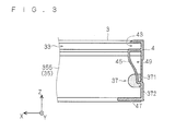
- the first frame 3 has the structure in which a groove-like fitting part 33 into which the side end part of the solar cell panel 2 is fitted and a first hollow member 35 having a first space 36 therein are provided to a perpendicular part 31 along the z-axis.
- the fitting part 33 and the first hollow member 35 extend along the longitudinal direction of the first frame 3.
- the first hollow member 35 comprises an outer part 351 along the z-axis direction, a ceiling part 353 linked to the outer part 351 in a substantially perpendicular manner, an inner part 355 that is linked to the ceiling part 353 in a substantially perpendicular manner and is parallel to the outer part 351, and a bottom part 357 linked to the outer part 351 and the inner part 355 in a substantially perpendicular manner.
- the outer part 351 constitutes part of the perpendicular part 31.
- the ceiling part 353 is part of the first hollow member 35 as well as part of the fitting part 33.
- a first drain port 37 is formed as a first communication hole in the first hollow member 35 by cutting out an end part of the inner part 355.
- the second frame 4 has the structure in which a groove-like fitting part 43 into which the side end of the solar cell panel 2 is fitted, a second hollow member 45 having a second space 46 therein, and a plate-like bottom 47 are provided to a perpendicular part 41 along the z-axis direction.
- the fitting part 43, the second hollow member 45 and the bottom 47 extend along the longitudinal direction of the second frame 4.
- the bottom 47 is mounted on the stand with fixing members such as bolts.
- the second hollow member 45 comprises an outer part 451 along the z-axis, a ceiling part 453 linked to the outer part 451 in a substantially perpendicular manner, an inner part 455 that is linked to the ceiling part 453 in a substantially perpendicular manner and is tilted relative to the outer part 451, and a bottom part 457 linked to the outer part 451 and the inner part 455 in a substantially perpendicular manner.
- the outer part 451 constitutes part of the above-mentioned perpendicular part 41.
- the ceiling part 453 is part of the second hollow member 45 as well as part of the fitting part 43.
- An opening 49 is formed on an end part of the second hollow member 45 in the longitudinal direction through which the inner space (second space 46) of the second hollow member 45 is communicated with the outside.
- the end part of the second hollow member 45 is cut out correspondingly to a shape of the end part of the first hollow member 35.
- an end surface of the first hollow member 35 is caused to abut against the perpendicular part 41.
- a bolt 51 is inserted into an insertion hole 53 provided in the perpendicular part 41, and is further screwed with a bolt hole 55 provided in a link part of the outer part 351 and the ceiling part 353.
- a bolt 61 is inserted into an insertion hole 63 provided to the perpendicular part 41 and is screwed with a bolt hole 65 provided to a link part of the inner part 355 and the bottom part 357.
- the first frame 3 and the second frame 4 are connected to each other by the connecting mechanism described above. Note that the connecting mechanism is not limited to those using bolts.
- the first drain port 37 includes an overlapping portion 371 (first opening region) that overlaps part of the opening 49, and the first space 36 and the second space 46 are connected in communication with each other through the overlapping portion 371.
- an opening position of the first drain port 37 is set such that the overlapping portion 371 overlaps a lower edge (bottom of a -Z side) of the opening 49.
- the first drain port 37 includes an exposed portion 372 (second opening region) exposed to the outside, and the first space 36 and the outer space are communicated with each other through the exposed portion 372.
- the water that has entered the first hollow member 35 is discharged to the outside through the exposed portion 372 of the first drain port 37.
- the water that has entered the second hollow member 45 is discharged through the overlapping portion 371 and the exposed portion 372 of the first drain port 37. That is, the water or the like entering the second hollow member 45 to be accumulated in the bottom can be discharged through the first drain port 37 without providing a drain port in the second frame 4.
- the strength of the first frame 3 is more enhanced compared with the second frame 4 by making a cross-sectional area of the first space 36 in cross section orthogonal to the longitudinal direction of the first frame 3 larger than a cross-sectional area of the second hollow space 46 in cross section orthogonal to the longitudinal direction of the second frame 4, which decreases an excessive reduction in strength due to the provision of the first drain port 37.
- the first drain port 37 is formed by cutting out in curved pattern so that stress can be dispersed in a curved edge portion. Accordingly, deformation of the first frame 3 can be reduced.
- the first hollow member 35, the second hollow member 45 and the outer space are communicated with each other through the first drain port 37, whereby it is possible to discharge the water that has entered the first hollow member 35 and the second hollow member 45 through the first drain port 37. Therefore, the number of processing steps can be reduced compared with a case where drain ports are individually provided to the first frame 3 and the second frame 4. Moreover, the number of drain ports can be reduced, and thus drainability can be enhanced without reducing the frame strength.
- a solar cell module 1a shown in Fig. 4 includes, in place of the first frame 3 according to the first embodiment, a first frame 3a in which a second drain port 39 as a second communication hole is further provided to a first hollow member 35a.
- the second drain port 39 is provided in the vicinity of an end part of a bottom part 357a in the longitudinal direction: the bottom of the first hollow member 35a.
- a first space 36a is communicated with the outer space also through the second drain port 39.
- the first drain port 37 is provided to an inner part 355a: a side part of the first hollow member 35a.
- the water accumulated in the bottom of the first hollow member 35a can be efficiently discharged by providing the second drain port 39, as indicated by dashed lines in Fig. 4 . Further, the water can be discharged through the second drain port 39 even in a case where the exposed portion 372 of the first drain port 37 is clogged with dust, moss or the like.
- a first drain port 37b having a substantially circular shape is provided at a position apart from the end part of an inner part 355b of a first hollow member 35b.
- the inside of a second hollow member 45a of a second frame 4a is a second space 46a being substantially rectangular in cross section. Further, an opening 49a for causing the second space 46a to be communicated with the outside is formed at the end part of the second hollow member 45b.
- a first drain port 37b in the state in which the first frame 3b and the second frame 4a are connected to each other, a first drain port 37b includes an overlapping portion 371b (first opening region) overlapping the opening 49a, and a first space 36b and the second space 46a are connected in communication with each other through the overlapping portion 371b.
- the first drain port 37b includes an exposed portion 372b (second opening region) exposed to the outside, and the first space 36b is communicated with the outer space through the exposed portion 372b.
- an opening position of the first drain port 37b is set such that the overlapping portion 371b overlaps a lower end part of the opening 49a. Accordingly, the water accumulated in the bottom of the second hollow member 45a can be efficiently discharged.
- the end part is not required to be processed by making the position at which the first drain port 37b is provided apart from the end part of the first hollow member 35b, which decreases a reduction in strength of the end part. As a result, it is possible to reduce deformations of the end part on which stress is most likely to occur.
- a first drain port 37c having a substantially circular shape is provided at a position apart from the end part of an inner part 355c of a first hollow member 35c.
- a second drain port 39c is provided at the end part of a bottom part 357c of the first hollow member 35c.
- a second hollow member 45b having a substantially rectangular shape in cross section is provided in a second frame 4b.
- An opening 49b for causing a second space 46b to be communicated with the outer space is formed at the end part of the second hollow member 45b.
- the first drain port 37c includes an overlapping portion 371c (first opening region) overlapping the opening 49b, and a first space 36c and the second space 46b are connected in communication with each other through the overlapping portion 371c.
- the first drain port 37c includes an exposed portion 372c (second opening region) exposed to the outside, and the first space 36c and the outer space are communicated with each other through the exposed portion 372c.
- an opening position of the first drain port 37c is set such that the overlapping portion 371c of the first drain port 37c overlaps the opening 49b at a position above a lower end part of the opening 49b.
- a first drain port 37d is provided so as to extend from an inner part 355d to a bottom part 357d.
- the first drain port 37d includes an overlapping portion 371d (first opening region) in which a portion that is open in the inner part 355d and an opening 49b overlap each other, and a first space 36d and a second space 46b are communicated with each other through the overlapping portion 371d.
- the first drain port 37d includes a portion (second opening region) that is open in the bottom part 357d, and the first space 36d and the outer space are communicated with each other through this portion.
- the first drain port 37d is provided as described above, whereby the water that has entered the insides of the first hollow member 35d and the second hollow member 45b can be discharged through the first drain port 37d, and the water accumulated in the bottom of the first hollow member 35d can be also efficiently discharged.
- a solar cell module when a solar cell module is installed on a stand, in a case where a portion on which a load is likely to be applied and a portion on which a load is unlikely to be applied are generated between frames mounted around a solar cell panel, it is possible to minimize a reduction in frame strength due to the provision of drain ports by employing the frame to which a first drain port and a second drain port are provided as the frame on which a load is unlikely to be applied.
- first drain ports are not necessarily required to be provided at four corners of the solar cell module, and at least, are only required to be provided on a lower side (side in a direction in which water flows). That is, in the solar cell module as described above, a first frame to which a first drain port that becomes a first communication hole is provided is disposed so as to be substantially parallel to the horizontal surface and a second frame is disposed along a tilted surface that is tilted relative to the horizontal surface.
- the arrangement as described above can reduce the drain ports, which enables a reduction in the number of processing steps. In addition, it is possible to reduce an occurrence of clogging of drain ports due to infiltration of dust or the like through a drain port that is unrelated to drainage.
- the present invention is beneficial to frames that protect a solar cell panel having a substrate structure or a laminated glass structure.
Landscapes
- Engineering & Computer Science (AREA)
- Physics & Mathematics (AREA)
- Life Sciences & Earth Sciences (AREA)
- Sustainable Development (AREA)
- Sustainable Energy (AREA)
- Thermal Sciences (AREA)
- Chemical & Material Sciences (AREA)
- Combustion & Propulsion (AREA)
- Mechanical Engineering (AREA)
- General Engineering & Computer Science (AREA)
- Photovoltaic Devices (AREA)
Applications Claiming Priority (2)
| Application Number | Priority Date | Filing Date | Title |
|---|---|---|---|
| JP2008081167 | 2008-03-26 | ||
| PCT/JP2009/056198 WO2009119775A1 (ja) | 2008-03-26 | 2009-03-26 | 太陽電池モジュール |
Publications (3)
| Publication Number | Publication Date |
|---|---|
| EP2267792A1 true EP2267792A1 (de) | 2010-12-29 |
| EP2267792A4 EP2267792A4 (de) | 2013-12-04 |
| EP2267792B1 EP2267792B1 (de) | 2014-12-31 |
Family
ID=41113962
Family Applications (1)
| Application Number | Title | Priority Date | Filing Date |
|---|---|---|---|
| EP09725859.4A Not-in-force EP2267792B1 (de) | 2008-03-26 | 2009-03-26 | Solarzellenmodul |
Country Status (5)
| Country | Link |
|---|---|
| US (1) | US8607511B2 (de) |
| EP (1) | EP2267792B1 (de) |
| JP (3) | JP4611454B2 (de) |
| CN (2) | CN101981706B (de) |
| WO (1) | WO2009119775A1 (de) |
Cited By (4)
| Publication number | Priority date | Publication date | Assignee | Title |
|---|---|---|---|---|
| US8607511B2 (en) | 2008-03-26 | 2013-12-17 | Kyocera Corporation | Solar cell module |
| WO2014060471A3 (de) * | 2012-10-17 | 2014-06-26 | Fraunhofer-Gesellschaft zur Förderung der angewandten Forschung e.V. | Hohlkammerprofil sowie photovoltaikmodul und verwendung eines reversibel komprimierbaren körpers |
| WO2017005239A1 (de) * | 2015-07-06 | 2017-01-12 | Hanwha Q Cells Gmbh | Solarmodul |
| US20240186944A1 (en) * | 2021-04-19 | 2024-06-06 | Origami Solar, Inc. | Interlocking Frame for Solar Panels |
Families Citing this family (17)
| Publication number | Priority date | Publication date | Assignee | Title |
|---|---|---|---|---|
| JP4515514B2 (ja) * | 2008-07-30 | 2010-08-04 | シャープ株式会社 | 太陽電池モジュール |
| DE102008045510A1 (de) * | 2008-09-03 | 2010-03-04 | Sapa Gmbh | Solarmodulrahmen mit Wasserablauf |
| JP4979665B2 (ja) * | 2008-09-29 | 2012-07-18 | シャープ株式会社 | 太陽電池装置 |
| JP5916565B2 (ja) * | 2012-08-28 | 2016-05-11 | シャープ株式会社 | 太陽電池モジュール |
| EP2811535B1 (de) * | 2012-02-03 | 2019-07-17 | Panasonic Intellectual Property Management Co., Ltd. | Solarzellenmodul |
| JP6021915B2 (ja) * | 2012-07-20 | 2016-11-09 | 三菱電機株式会社 | 保持フレームおよび太陽電池モジュール |
| JP6183581B2 (ja) * | 2012-09-28 | 2017-08-23 | パナソニックIpマネジメント株式会社 | 太陽電池モジュール |
| WO2014080624A1 (ja) * | 2012-11-21 | 2014-05-30 | 三洋電機株式会社 | 太陽電池モジュール |
| US20150136196A1 (en) * | 2013-11-21 | 2015-05-21 | Mark Edward Williamson | Self-cleaning solar panel design |
| JP2015149412A (ja) * | 2014-02-06 | 2015-08-20 | 三菱電機株式会社 | 太陽電池モジュール |
| JP6325898B2 (ja) * | 2014-05-28 | 2018-05-16 | シャープ株式会社 | 太陽電池モジュールおよび太陽電池モジュール用枠体 |
| WO2016031915A1 (ja) * | 2014-08-28 | 2016-03-03 | 京セラ株式会社 | 太陽電池モジュール |
| JP6505404B2 (ja) * | 2014-09-19 | 2019-04-24 | ソーラーフロンティア株式会社 | 太陽電池モジュール |
| JP6453074B2 (ja) * | 2014-12-24 | 2019-01-16 | シャープ株式会社 | 太陽電池モジュール |
| JP6497933B2 (ja) * | 2014-12-24 | 2019-04-10 | シャープ株式会社 | 太陽電池モジュール |
| DE102015121615A1 (de) * | 2015-12-11 | 2017-06-14 | Hanwha Q Cells Gmbh | Solarmodul und Solarmodulrahmen |
| JP7572242B2 (ja) * | 2018-12-27 | 2024-10-23 | 出光興産株式会社 | パネル状モジュール用のフレーム及びパネル状モジュール用のフレーム構造体 |
Family Cites Families (15)
| Publication number | Priority date | Publication date | Assignee | Title |
|---|---|---|---|---|
| US2706543A (en) * | 1950-07-25 | 1955-04-19 | H A Kammerer Inc | Construction for doors and like closures |
| US2914145A (en) * | 1955-01-26 | 1959-11-24 | Benson Russell Richard | Curtain wall framing |
| US3845599A (en) * | 1969-08-18 | 1974-11-05 | Comalco Ind Pty Ltd | Window drain valve |
| US3636660A (en) * | 1970-03-09 | 1972-01-25 | Gerald D Peterson | Internal vent for window sash |
| DE3301161A1 (de) | 1983-01-15 | 1984-07-19 | Bayer Ag, 5090 Leverkusen | Thermoplastische formmassen |
| JPS59138251U (ja) * | 1983-03-07 | 1984-09-14 | 株式会社ほくさん | 太陽電池パネルの取付装置 |
| US4553361A (en) * | 1984-07-05 | 1985-11-19 | Cole Sewell Corporation | Tiered drain channel for extruded door insert |
| GB2167058B (en) | 1984-11-21 | 1988-06-08 | Smidth & Co As F L | Method and apparatus for cooling white cement clinker |
| JPS61127650U (de) * | 1985-01-29 | 1986-08-11 | ||
| JPH11325610A (ja) * | 1998-05-12 | 1999-11-26 | Mitsubishi Electric Corp | 太陽エネルギー利用装置 |
| JP2003282919A (ja) | 2002-03-27 | 2003-10-03 | Kyocera Corp | 太陽電池モジュール |
| JP4368151B2 (ja) * | 2003-06-27 | 2009-11-18 | 三洋電機株式会社 | 太陽電池モジュール |
| US7987644B2 (en) * | 2006-09-15 | 2011-08-02 | Enclos Corporation | Curtainwall system |
| US8607511B2 (en) * | 2008-03-26 | 2013-12-17 | Kyocera Corporation | Solar cell module |
| US8458968B2 (en) * | 2010-07-21 | 2013-06-11 | Panda Windows & Doors, Inc. | Track assembly having multiple panels with drain method and device |
-
2009
- 2009-03-26 US US12/934,998 patent/US8607511B2/en not_active Expired - Fee Related
- 2009-03-26 WO PCT/JP2009/056198 patent/WO2009119775A1/ja not_active Ceased
- 2009-03-26 CN CN2009801108646A patent/CN101981706B/zh not_active Expired - Fee Related
- 2009-03-26 JP JP2010505805A patent/JP4611454B2/ja active Active
- 2009-03-26 CN CN201210453517.7A patent/CN102945874B/zh not_active Expired - Fee Related
- 2009-03-26 EP EP09725859.4A patent/EP2267792B1/de not_active Not-in-force
-
2010
- 2010-10-13 JP JP2010230867A patent/JP4829374B2/ja active Active
-
2011
- 2011-09-15 JP JP2011201609A patent/JP5591200B2/ja active Active
Non-Patent Citations (2)
| Title |
|---|
| No further relevant documents disclosed * |
| See also references of WO2009119775A1 * |
Cited By (5)
| Publication number | Priority date | Publication date | Assignee | Title |
|---|---|---|---|---|
| US8607511B2 (en) | 2008-03-26 | 2013-12-17 | Kyocera Corporation | Solar cell module |
| WO2014060471A3 (de) * | 2012-10-17 | 2014-06-26 | Fraunhofer-Gesellschaft zur Förderung der angewandten Forschung e.V. | Hohlkammerprofil sowie photovoltaikmodul und verwendung eines reversibel komprimierbaren körpers |
| WO2017005239A1 (de) * | 2015-07-06 | 2017-01-12 | Hanwha Q Cells Gmbh | Solarmodul |
| US20240186944A1 (en) * | 2021-04-19 | 2024-06-06 | Origami Solar, Inc. | Interlocking Frame for Solar Panels |
| US12388394B2 (en) * | 2021-04-19 | 2025-08-12 | Origami Solar, Inc. | Interlocking frame for solar panels |
Also Published As
| Publication number | Publication date |
|---|---|
| JP4611454B2 (ja) | 2011-01-12 |
| US20110011446A1 (en) | 2011-01-20 |
| JP5591200B2 (ja) | 2014-09-17 |
| JP2011009792A (ja) | 2011-01-13 |
| EP2267792A4 (de) | 2013-12-04 |
| CN102945874B (zh) | 2015-05-06 |
| US8607511B2 (en) | 2013-12-17 |
| CN101981706A (zh) | 2011-02-23 |
| WO2009119775A1 (ja) | 2009-10-01 |
| CN102945874A (zh) | 2013-02-27 |
| EP2267792B1 (de) | 2014-12-31 |
| JP2011254109A (ja) | 2011-12-15 |
| JP4829374B2 (ja) | 2011-12-07 |
| JPWO2009119775A1 (ja) | 2011-07-28 |
| CN101981706B (zh) | 2012-12-26 |
Similar Documents
| Publication | Publication Date | Title |
|---|---|---|
| EP2267792B1 (de) | Solarzellenmodul | |
| EP2259332B1 (de) | Solarzellenmodul | |
| JP5405278B2 (ja) | 太陽電池モジュール及びその製造方法 | |
| US20050103376A1 (en) | Solar cell module and manufacturing method therefor | |
| US20120233840A1 (en) | Solar cell module and manufacturing method of same | |
| EP2849234A1 (de) | Solarzellenvorrichtung | |
| JP6501072B2 (ja) | 太陽電池システム | |
| WO2012128342A1 (ja) | 太陽電池パネル、太陽電池モジュールおよび太陽電池モジュールの製造方法 | |
| CN103828227B (zh) | 带有安装孔的无框太阳能模块 | |
| US20130000689A1 (en) | Photovoltaic module support assembly with standoff clamps | |
| JP2009141216A (ja) | 太陽電池モジュール | |
| US20160285406A1 (en) | Solar cell array | |
| JP2013120772A (ja) | 太陽電池モジュール用枠体、太陽電池モジュール、および太陽電池モジュール用枠体の製造方法 | |
| US10439548B2 (en) | Solar cell module and solar cell array | |
| CN210273946U (zh) | 一种太阳能光伏组件边框 | |
| JP5279330B2 (ja) | 太陽電池モジュール | |
| JP2010199366A (ja) | 太陽電池モジュールおよび太陽光発電システム | |
| CN223348605U (zh) | 光伏边框、光伏组件及光伏组件系统 | |
| JP5456188B2 (ja) | 太陽電池モジュール | |
| EP4160907A1 (de) | Fotovoltaikmodul | |
| JP2013157477A (ja) | 太陽電池モジュール、太陽電池モジュールの製造方法および補助部材 | |
| KR20250153405A (ko) | 태양광 모듈 및 그 태양광 모듈 제조방법 | |
| JP6301737B2 (ja) | 太陽電池装置 | |
| JP2013048232A (ja) | 太陽電池モジュール |
Legal Events
| Date | Code | Title | Description |
|---|---|---|---|
| PUAI | Public reference made under article 153(3) epc to a published international application that has entered the european phase |
Free format text: ORIGINAL CODE: 0009012 |
|
| 17P | Request for examination filed |
Effective date: 20101004 |
|
| AK | Designated contracting states |
Kind code of ref document: A1 Designated state(s): AT BE BG CH CY CZ DE DK EE ES FI FR GB GR HR HU IE IS IT LI LT LU LV MC MK MT NL NO PL PT RO SE SI SK TR |
|
| AX | Request for extension of the european patent |
Extension state: AL BA RS |
|
| DAX | Request for extension of the european patent (deleted) | ||
| A4 | Supplementary search report drawn up and despatched |
Effective date: 20131106 |
|
| RIC1 | Information provided on ipc code assigned before grant |
Ipc: H01L 31/042 20060101AFI20131030BHEP |
|
| GRAP | Despatch of communication of intention to grant a patent |
Free format text: ORIGINAL CODE: EPIDOSNIGR1 |
|
| INTG | Intention to grant announced |
Effective date: 20140807 |
|
| GRAS | Grant fee paid |
Free format text: ORIGINAL CODE: EPIDOSNIGR3 |
|
| GRAA | (expected) grant |
Free format text: ORIGINAL CODE: 0009210 |
|
| AK | Designated contracting states |
Kind code of ref document: B1 Designated state(s): AT BE BG CH CY CZ DE DK EE ES FI FR GB GR HR HU IE IS IT LI LT LU LV MC MK MT NL NO PL PT RO SE SI SK TR |
|
| REG | Reference to a national code |
Ref country code: CH Ref legal event code: EP Ref country code: GB Ref legal event code: FG4D |
|
| REG | Reference to a national code |
Ref country code: IE Ref legal event code: FG4D |
|
| REG | Reference to a national code |
Ref country code: AT Ref legal event code: REF Ref document number: 704849 Country of ref document: AT Kind code of ref document: T Effective date: 20150215 |
|
| REG | Reference to a national code |
Ref country code: DE Ref legal event code: R096 Ref document number: 602009028681 Country of ref document: DE Effective date: 20150219 |
|
| PG25 | Lapsed in a contracting state [announced via postgrant information from national office to epo] |
Ref country code: LT Free format text: LAPSE BECAUSE OF FAILURE TO SUBMIT A TRANSLATION OF THE DESCRIPTION OR TO PAY THE FEE WITHIN THE PRESCRIBED TIME-LIMIT Effective date: 20141231 Ref country code: NO Free format text: LAPSE BECAUSE OF FAILURE TO SUBMIT A TRANSLATION OF THE DESCRIPTION OR TO PAY THE FEE WITHIN THE PRESCRIBED TIME-LIMIT Effective date: 20150331 Ref country code: FI Free format text: LAPSE BECAUSE OF FAILURE TO SUBMIT A TRANSLATION OF THE DESCRIPTION OR TO PAY THE FEE WITHIN THE PRESCRIBED TIME-LIMIT Effective date: 20141231 |
|
| REG | Reference to a national code |
Ref country code: NL Ref legal event code: VDEP Effective date: 20141231 |
|
| REG | Reference to a national code |
Ref country code: LT Ref legal event code: MG4D |
|
| PG25 | Lapsed in a contracting state [announced via postgrant information from national office to epo] |
Ref country code: GR Free format text: LAPSE BECAUSE OF FAILURE TO SUBMIT A TRANSLATION OF THE DESCRIPTION OR TO PAY THE FEE WITHIN THE PRESCRIBED TIME-LIMIT Effective date: 20150401 Ref country code: HR Free format text: LAPSE BECAUSE OF FAILURE TO SUBMIT A TRANSLATION OF THE DESCRIPTION OR TO PAY THE FEE WITHIN THE PRESCRIBED TIME-LIMIT Effective date: 20141231 Ref country code: SE Free format text: LAPSE BECAUSE OF FAILURE TO SUBMIT A TRANSLATION OF THE DESCRIPTION OR TO PAY THE FEE WITHIN THE PRESCRIBED TIME-LIMIT Effective date: 20141231 Ref country code: LV Free format text: LAPSE BECAUSE OF FAILURE TO SUBMIT A TRANSLATION OF THE DESCRIPTION OR TO PAY THE FEE WITHIN THE PRESCRIBED TIME-LIMIT Effective date: 20141231 |
|
| REG | Reference to a national code |
Ref country code: AT Ref legal event code: MK05 Ref document number: 704849 Country of ref document: AT Kind code of ref document: T Effective date: 20141231 |
|
| PG25 | Lapsed in a contracting state [announced via postgrant information from national office to epo] |
Ref country code: NL Free format text: LAPSE BECAUSE OF FAILURE TO SUBMIT A TRANSLATION OF THE DESCRIPTION OR TO PAY THE FEE WITHIN THE PRESCRIBED TIME-LIMIT Effective date: 20141231 |
|
| REG | Reference to a national code |
Ref country code: DE Ref legal event code: R082 Ref document number: 602009028681 Country of ref document: DE Representative=s name: VIERING, JENTSCHURA & PARTNER PATENT- UND RECH, DE Ref country code: DE Ref legal event code: R082 Ref document number: 602009028681 Country of ref document: DE Representative=s name: VIERING, JENTSCHURA & PARTNER MBB PATENT- UND , DE |
|
| PG25 | Lapsed in a contracting state [announced via postgrant information from national office to epo] |
Ref country code: RO Free format text: LAPSE BECAUSE OF FAILURE TO SUBMIT A TRANSLATION OF THE DESCRIPTION OR TO PAY THE FEE WITHIN THE PRESCRIBED TIME-LIMIT Effective date: 20141231 Ref country code: SK Free format text: LAPSE BECAUSE OF FAILURE TO SUBMIT A TRANSLATION OF THE DESCRIPTION OR TO PAY THE FEE WITHIN THE PRESCRIBED TIME-LIMIT Effective date: 20141231 Ref country code: CZ Free format text: LAPSE BECAUSE OF FAILURE TO SUBMIT A TRANSLATION OF THE DESCRIPTION OR TO PAY THE FEE WITHIN THE PRESCRIBED TIME-LIMIT Effective date: 20141231 Ref country code: ES Free format text: LAPSE BECAUSE OF FAILURE TO SUBMIT A TRANSLATION OF THE DESCRIPTION OR TO PAY THE FEE WITHIN THE PRESCRIBED TIME-LIMIT Effective date: 20141231 |
|
| PG25 | Lapsed in a contracting state [announced via postgrant information from national office to epo] |
Ref country code: PL Free format text: LAPSE BECAUSE OF FAILURE TO SUBMIT A TRANSLATION OF THE DESCRIPTION OR TO PAY THE FEE WITHIN THE PRESCRIBED TIME-LIMIT Effective date: 20141231 Ref country code: AT Free format text: LAPSE BECAUSE OF FAILURE TO SUBMIT A TRANSLATION OF THE DESCRIPTION OR TO PAY THE FEE WITHIN THE PRESCRIBED TIME-LIMIT Effective date: 20141231 Ref country code: IS Free format text: LAPSE BECAUSE OF FAILURE TO SUBMIT A TRANSLATION OF THE DESCRIPTION OR TO PAY THE FEE WITHIN THE PRESCRIBED TIME-LIMIT Effective date: 20150430 |
|
| REG | Reference to a national code |
Ref country code: DE Ref legal event code: R097 Ref document number: 602009028681 Country of ref document: DE |
|
| PG25 | Lapsed in a contracting state [announced via postgrant information from national office to epo] |
Ref country code: DK Free format text: LAPSE BECAUSE OF FAILURE TO SUBMIT A TRANSLATION OF THE DESCRIPTION OR TO PAY THE FEE WITHIN THE PRESCRIBED TIME-LIMIT Effective date: 20141231 Ref country code: EE Free format text: LAPSE BECAUSE OF FAILURE TO SUBMIT A TRANSLATION OF THE DESCRIPTION OR TO PAY THE FEE WITHIN THE PRESCRIBED TIME-LIMIT Effective date: 20141231 Ref country code: MC Free format text: LAPSE BECAUSE OF FAILURE TO SUBMIT A TRANSLATION OF THE DESCRIPTION OR TO PAY THE FEE WITHIN THE PRESCRIBED TIME-LIMIT Effective date: 20141231 Ref country code: LU Free format text: LAPSE BECAUSE OF FAILURE TO SUBMIT A TRANSLATION OF THE DESCRIPTION OR TO PAY THE FEE WITHIN THE PRESCRIBED TIME-LIMIT Effective date: 20150326 |
|
| REG | Reference to a national code |
Ref country code: CH Ref legal event code: PL |
|
| PLBE | No opposition filed within time limit |
Free format text: ORIGINAL CODE: 0009261 |
|
| STAA | Information on the status of an ep patent application or granted ep patent |
Free format text: STATUS: NO OPPOSITION FILED WITHIN TIME LIMIT |
|
| GBPC | Gb: european patent ceased through non-payment of renewal fee |
Effective date: 20150331 |
|
| 26N | No opposition filed |
Effective date: 20151001 |
|
| PG25 | Lapsed in a contracting state [announced via postgrant information from national office to epo] |
Ref country code: IT Free format text: LAPSE BECAUSE OF FAILURE TO SUBMIT A TRANSLATION OF THE DESCRIPTION OR TO PAY THE FEE WITHIN THE PRESCRIBED TIME-LIMIT Effective date: 20141231 |
|
| REG | Reference to a national code |
Ref country code: FR Ref legal event code: ST Effective date: 20151130 |
|
| REG | Reference to a national code |
Ref country code: IE Ref legal event code: MM4A |
|
| PG25 | Lapsed in a contracting state [announced via postgrant information from national office to epo] |
Ref country code: IE Free format text: LAPSE BECAUSE OF NON-PAYMENT OF DUE FEES Effective date: 20150326 Ref country code: GB Free format text: LAPSE BECAUSE OF NON-PAYMENT OF DUE FEES Effective date: 20150331 Ref country code: LI Free format text: LAPSE BECAUSE OF NON-PAYMENT OF DUE FEES Effective date: 20150331 Ref country code: CH Free format text: LAPSE BECAUSE OF NON-PAYMENT OF DUE FEES Effective date: 20150331 |
|
| PG25 | Lapsed in a contracting state [announced via postgrant information from national office to epo] |
Ref country code: SI Free format text: LAPSE BECAUSE OF FAILURE TO SUBMIT A TRANSLATION OF THE DESCRIPTION OR TO PAY THE FEE WITHIN THE PRESCRIBED TIME-LIMIT Effective date: 20141231 Ref country code: FR Free format text: LAPSE BECAUSE OF NON-PAYMENT OF DUE FEES Effective date: 20150331 |
|
| PG25 | Lapsed in a contracting state [announced via postgrant information from national office to epo] |
Ref country code: BE Free format text: LAPSE BECAUSE OF FAILURE TO SUBMIT A TRANSLATION OF THE DESCRIPTION OR TO PAY THE FEE WITHIN THE PRESCRIBED TIME-LIMIT Effective date: 20141231 |
|
| PG25 | Lapsed in a contracting state [announced via postgrant information from national office to epo] |
Ref country code: MT Free format text: LAPSE BECAUSE OF FAILURE TO SUBMIT A TRANSLATION OF THE DESCRIPTION OR TO PAY THE FEE WITHIN THE PRESCRIBED TIME-LIMIT Effective date: 20141231 |
|
| PG25 | Lapsed in a contracting state [announced via postgrant information from national office to epo] |
Ref country code: BG Free format text: LAPSE BECAUSE OF FAILURE TO SUBMIT A TRANSLATION OF THE DESCRIPTION OR TO PAY THE FEE WITHIN THE PRESCRIBED TIME-LIMIT Effective date: 20141231 Ref country code: HU Free format text: LAPSE BECAUSE OF FAILURE TO SUBMIT A TRANSLATION OF THE DESCRIPTION OR TO PAY THE FEE WITHIN THE PRESCRIBED TIME-LIMIT; INVALID AB INITIO Effective date: 20090326 |
|
| PG25 | Lapsed in a contracting state [announced via postgrant information from national office to epo] |
Ref country code: CY Free format text: LAPSE BECAUSE OF FAILURE TO SUBMIT A TRANSLATION OF THE DESCRIPTION OR TO PAY THE FEE WITHIN THE PRESCRIBED TIME-LIMIT Effective date: 20141231 |
|
| PG25 | Lapsed in a contracting state [announced via postgrant information from national office to epo] |
Ref country code: PT Free format text: LAPSE BECAUSE OF FAILURE TO SUBMIT A TRANSLATION OF THE DESCRIPTION OR TO PAY THE FEE WITHIN THE PRESCRIBED TIME-LIMIT Effective date: 20150501 |
|
| PG25 | Lapsed in a contracting state [announced via postgrant information from national office to epo] |
Ref country code: TR Free format text: LAPSE BECAUSE OF FAILURE TO SUBMIT A TRANSLATION OF THE DESCRIPTION OR TO PAY THE FEE WITHIN THE PRESCRIBED TIME-LIMIT Effective date: 20141231 |
|
| PG25 | Lapsed in a contracting state [announced via postgrant information from national office to epo] |
Ref country code: MK Free format text: LAPSE BECAUSE OF FAILURE TO SUBMIT A TRANSLATION OF THE DESCRIPTION OR TO PAY THE FEE WITHIN THE PRESCRIBED TIME-LIMIT Effective date: 20141231 |
|
| P01 | Opt-out of the competence of the unified patent court (upc) registered |
Effective date: 20230505 |
|
| PGFP | Annual fee paid to national office [announced via postgrant information from national office to epo] |
Ref country code: DE Payment date: 20240130 Year of fee payment: 16 |
|
| REG | Reference to a national code |
Ref country code: DE Ref legal event code: R079 Ref document number: 602009028681 Country of ref document: DE Free format text: PREVIOUS MAIN CLASS: H01L0031042000 Ipc: H10F0019000000 |
|
| REG | Reference to a national code |
Ref country code: DE Ref legal event code: R119 Ref document number: 602009028681 Country of ref document: DE |
|
| PG25 | Lapsed in a contracting state [announced via postgrant information from national office to epo] |
Ref country code: DE Free format text: LAPSE BECAUSE OF NON-PAYMENT OF DUE FEES Effective date: 20251001 |