EP2267862A2 - Ladesystem und Verfahren zur Regelung des Ladevorgangs abhängig von Temperatur und Spannung - Google Patents
Ladesystem und Verfahren zur Regelung des Ladevorgangs abhängig von Temperatur und Spannung Download PDFInfo
- Publication number
- EP2267862A2 EP2267862A2 EP10161040A EP10161040A EP2267862A2 EP 2267862 A2 EP2267862 A2 EP 2267862A2 EP 10161040 A EP10161040 A EP 10161040A EP 10161040 A EP10161040 A EP 10161040A EP 2267862 A2 EP2267862 A2 EP 2267862A2
- Authority
- EP
- European Patent Office
- Prior art keywords
- battery
- temperature
- electric quantity
- threshold
- voltage
- Prior art date
- Legal status (The legal status is an assumption and is not a legal conclusion. Google has not performed a legal analysis and makes no representation as to the accuracy of the status listed.)
- Withdrawn
Links
Images

Classifications
-
- H—ELECTRICITY
- H02—GENERATION; CONVERSION OR DISTRIBUTION OF ELECTRIC POWER
- H02J—ELECTRIC POWER NETWORKS; CIRCUIT ARRANGEMENTS OR SYSTEMS FOR SUPPLYING OR DISTRIBUTING ELECTRIC POWER; SYSTEMS FOR STORING ELECTRIC ENERGY
- H02J7/00—Circuit arrangements for charging or discharging batteries or for supplying loads from batteries
- H02J7/90—Regulation of charging or discharging current or voltage
- H02J7/971—Regulation of charging or discharging current or voltage the charge cycle being controlled or terminated in response to non-electric parameters
- H02J7/975—Regulation of charging or discharging current or voltage the charge cycle being controlled or terminated in response to non-electric parameters in response to temperature
- H02J7/977—Regulation of charging or discharging current or voltage the charge cycle being controlled or terminated in response to non-electric parameters in response to temperature of the battery
-
- H—ELECTRICITY
- H02—GENERATION; CONVERSION OR DISTRIBUTION OF ELECTRIC POWER
- H02J—ELECTRIC POWER NETWORKS; CIRCUIT ARRANGEMENTS OR SYSTEMS FOR SUPPLYING OR DISTRIBUTING ELECTRIC POWER; SYSTEMS FOR STORING ELECTRIC ENERGY
- H02J7/00—Circuit arrangements for charging or discharging batteries or for supplying loads from batteries
- H02J7/90—Regulation of charging or discharging current or voltage
- H02J7/96—Regulation of charging or discharging current or voltage in response to battery voltage
Definitions
- the invention relates to a method for charging a battery and, more particularly, to a technique for charging a battery at a high temperature.
- a typical battery charger includes three control circuits, a constant current control circuit, a constant voltage control circuit, and a constant temperature control circuit.
- the battery charger enters a constant current mode.
- the constant current control circuit may keep a stable charging current to charge the battery.
- the temperature of a conventional charger is between 0 degree centigrade (°C) and 45 °C, and the conventional charger may charge the battery continuously in the constant current mode as long as the voltage of the battery is less than 4.2 volts (V).
- V 4.2 volts
- the conventional charger When the voltage of the battery reaches a preset voltage which is usually 4.2V, the conventional charger enters the constant voltage mode. At that moment, the constant voltage control circuit in the conventional charger may charge the battery with a constant voltage.
- the constant temperature control circuit detects that the temperature of the battery is higher than 45 °C, to avoid the expansion and liquid leakage caused by charging the battery at 4.2V voltage and high temperature, even the voltage of the battery does not reach 4.2V, the conventional charger stops charging the battery immediately when the preset temperature such as 45 °C is reached.
- a battery cell may be charged with a small constant voltage such as 4.1 V at the temperature between 45°C and 60 °C. The conventional charger cannot switch the charging voltage according to the temperature change.
- the invention discloses a charging system which may charge a battery in a wider temperature range.
- the battery may achieve high voltage in the charge process at high temperature without changing hardware or a charging chip greatly.
- the invention discloses a method for managing electric quantity of a battery, which may charge a battery normally in different temperatures and avoid problems such as the expansion of a battery cell.
- the invention discloses a charging system which may charge a battery in a wider range.
- the invention includes a charger and a detecting unit.
- the detecting unit may measure a plurality of electrical parameters of the battery. When the temperature of the battery is lower than a first threshold temperature, the charger may charge the battery normally. When the temperature of the battery is higher than the first threshold temperature but lower than a second threshold temperature, the detecting unit may determine whether the electric quantity of the battery is lower than a first threshold voltage. If the temperature of the battery is between the first threshold temperature and the second threshold temperature, and the electric quantity of the battery is lower than the first threshold temperature, the charger charges the battery continuously.
- the detecting unit makes the charger stop charging the battery any more.
- the detecting system also may be used for stopping charging the battery.
- the battery may be coupled to an electronic device during charging. Therefore, when the detecting unit determines that the temperature of the battery is larger than the second threshold temperature and the electric quantity is larger than a second threshold voltage, if the battery is coupled to an electronic device, the detecting unit may start the electronic device to discharge the battery to power the electronic device.
- the second threshold voltage is lower than the first threshold voltage.
- the invention also discloses a method for managing the electric quantity of a battery.
- the method including the following steps. First, when the temperature of the battery is lower than a first threshold temperature, a battery is charged normally. Second, when the temperature of the battery is higher than the first threshold temperature and is lower than a second threshold temperature, and the electric quantity of the battery is lower than a first threshold voltage, the battery is charged continuously. On the contrary, when the temperature of the battery is between the first threshold temperature and the second threshold temperature, and the electric quantity of the battery is higher than the first threshold voltage, the battery is not charged any more.
- the battery is also not charged any more.
- the battery may be charged continuously without changing hardware or charging chip greatly when the temperature of the battery is between the first threshold temperature and the second threshold temperature, and the electric quantity of the battery is lower than a first threshold voltage. Therefore, the battery may be charged in a wider temperature range, and the expansion of the battery is usually avoided when the battery is charged at a high temperature and a high voltage.
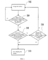
- FIG. 1 is a flow chart showing a method for managing an electric quantity of a battery in an embodiment of the invention
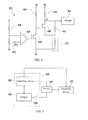
- FIG. 2 is a block diagram showing a charging system in an embodiment of the invention
- FIG. 3 is a block diagram showing a charging system in another embodiment of the invention.
- FIG. 4 is a circuit diagram showing the detecting unit in FIG. 3 in an embodiment of the invention.
- FIG. 5 is a circuit diagram showing that the battery is coupled to an electronic device during a charging process in an embodiment of the invention.
- FIG. 1 is a flow chart showing a method for managing an electric quantity of a battery in an embodiment of the invention.
- the battery adapted to the managing method disclosed in the embodiment may be a lithium battery.
- step S102 is performedis performedneedingeddch as 45 onic deviceatteryure teh abexceeds the f't'v or teh f'f't and the s't't, bu the e'q of the batt, and then step S104 is performed to determine whether the temperature of the battery is higher than a first threshold temperature.
- the first threshold temperature is preferably 45 °C, but it is not limited thereto.
- step S102 If the temperature of the battery does not exceed the first threshold temperature ("no" denoted in step S104), step S102 is continuously performed to charge the battery normally. However, if the temperature of the battery exceeds the first threshold temperature ("yes" denoted in step S104), step S106 is further performed to determine whether the temperature of the battery is higher than a second threshold temperature.
- the second threshold temperature is preferably 60 °C, but it is not limited thereto.
- step S 108 is selectively performed, and that is, whether the electric quantity(voltage values) of the battery exceeds a first threshold voltage is further determined.
- the first threshold voltage may be higher than 3.1V but lower than 4.2V, and for example, it may be 4.1V.
- step S108 if the temperature of the battery is determined between first threshold temperature and the second threshold temperature, and the electric quantity(voltage values) of the battery does not exceed the first threshold voltage ("no" denoted in step S 108), the method goes back to step S 102 to charge the battery continuously.
- step S106 if the temperature of the battery exceeds the second threshold temperature ("yes" denoted in step S106), as shown in step S 110 in the embodiment, the battery is not charged any more.
- the battery is not charged any more to avoid possible problems such as the battery expansion.
- FIG. 2 is a block diagram showing a charging system in the embodiment of the invention.
- a charging system 200 in the embodiment may charge a battery 210 (a lithium battery).
- the charging system 200 includes a detecting unit 202 and a charger 204.
- the detecting unit 202 is coupled to the charger 204.
- the detecting unit 202 may be realized by software in some embodiment or a microprocessor, in some other embodiments, and it is not limited in the invention.
- the charging system 200 also includes a switch unit 206 coupled to an end of the charger 204 and an end of the battery 210.
- the charger 204 may control the switch unit 206 to be on or off. Then, the charger 204 determines whether the voltage at an output end reaches a preset voltage (and a detecting result DET is also outputted to the charger 204).
- the preset voltage is, for example, 4.2V. If the voltage at the outputted end of the charger 204 does not reach the preset voltage, a constant current is provided to charge the battery 210, and the constant current may be 500 mill amperes (mA).
- the charger 204 if the voltage outputted by the charger 204 reaches the preset voltage, the charger 204 provides a constant voltage source to the battery 210.
- the potential of the voltage source may be the same as the preset voltage, and they are both 4.2 V However, it is also not limited in the invention.
- the battery 210 may have a testing unit 212.
- the detecting unit 202 may obtain a plurality of instant electrical parameters of the battery 210 via the testing unit 212.
- the electrical parameters include a temperature of the battery, a voltage, a current and so on.
- the detecting unit 202 obtains the instant electrical parameters of the battery 210, the electrical parameters may be taken as a detecting result DET to be sent to the charger 204.
- a first threshold temperature such as 45 °C
- the detecting unit 202 may determine whether the electric quantity (voltage values)of the battery 210 exceeds the first threshold voltage (such as 4.1 V).
- the charger 204 charges the battery 210 continuously.
- the charger 204 may open the switch unit 206 according to the detecting result DET to stop charging the battery 210.
- the charger 204 also may open the switch unit 206 according to the detecting result DET to stop charging the battery 210.
- the charging system 200 also may turn off the switch unit 206 to stop charging the battery.
- the testing unit 212 is disposed in the battery 210. In other embodiments, the testing unit 212 also may be disposed in the charger 204 or separately disposed in the electronic device, and it is not limited in the invention.
- FIG. 3 is a block diagram showing a charging system in another embodiment of the invention.
- a charging system 300 in the embodiment also may charge a battery 310 (lithium battery).
- the charging system 300 also includes a detecting unit 302, a charger 304, and a switch unit 306.
- the detecting unit 302 may be coupled to a positive pole and a negative pole of the battery 310, and it also may be coupled to the charger 304.
- the charger 304 may be coupled to the battery 310 via the switch unit 306.
- the battery 310 in the embodiment does not have the testing unit 212 in FIG. 2 . Therefore, the detecting unit 302 needs to detect the electric quantity (voltage values) of the battery 310 by measuring the voltage difference between the positive pole and negative pole of the battery 310.
- the battery 310 also may include a thermal sensing unit 312 such as a thermal resistor.
- the electrical characteristic of the thermal sensing unit 312, such as the resistance value, may change along with an environment temperature. Therefore, the charger 304 may determine the temperature of the battery 310 according to the electrical characteristic of the thermal sensing unit 312.
- other operating modes are the same as those in FIG. 2 , and they are not illustrated herein for a concise purpose.
- FIG. 4 is a circuit diagram showing the detecting unit in FIG. 3 in an embodiment of the invention.
- the detecting unit 302 includes a comparator 402, transistors 404 and 406, and resistors 408, 410, 412, 414 and 416.
- a first input end of the comparator 402 may receive an output voltage Vbat of the battery 310 namely the voltage difference between the positive pole and negative pole of the battery 310 via the resistor 408.
- the first input end of the comparator 402 also may be connected to the ground via the resistor 410.
- the second input end of the comparator 402 may be coupled to a reference voltage Vref.
- the output end of the comparator 402 is coupled to the gate of the transistor 404, a first source end and the first drain end of the transistor 404 is coupled to a first voltage bias V1 via the resistor 412, and a second source end and the second drain end is connected to the ground.
- the gate of the transistor 406 is coupled to the first source end and the first drain end of the transistor 404, and the first source end and the first drain end of the transistor 406 is coupled to a second voltage bias V2 via the resistor 414.
- the second source end and the second drain end of the transistor 406 may be connected to the ground via the thermal sensing unit 312 and coupled to the first source end the first drain end of the transistor 406 to form a node A1 via the resistor 416.
- both the transistors 404 and 406 may be N-mental-oxide-semiconductor (NMOS) transistors.
- the first input end of the comparator 402 receives a partial voltage of the output voltage Vbat of the battery 310.
- R1, R2 and R3 are the resistances of resistors 414 and 416, and the thermal sensing unit 312, respectively.
- the resistance of the thermal sensing unit 312 may change along with the temperature change.
- V A ⁇ 1 V ⁇ 1 ⁇ R ⁇ 3 R ⁇ 1 + R ⁇ 3
- the potential of the node A1 when the voltage of the battery Vbat exceeds the first threshold voltage may exceeds the potential of the node A1 when the voltage of the battery Vbat is lower than the first threshold voltage.
- a cut off charging temperature set by the charger 304 is higher, which may be 60 °C.
- the charger 304 may reduce the cut off charging temperature to a temperature such as 45 °C by changing the resistance or the partial voltage via the above circuit.
- the charger 304 allows the temperature of the battery 310 to be low. For example, when the voltage of the battery Vbat exceeds 4.1V, and the temperature of the battery 310 is higher than 45 °C (but lower than 60 °C), the charger 304 may open the switching unit 306 to stop charging the battery 310. On the contrary, when the voltage of the battery Vbat is lower than 4.1V, even the temperature of the battery 310 is between 45 °C to 60 °C, the charger 304 also may conduct the switching unit 306 to charge the battery 310 continuously.
- FIG. 5 is a circuit diagram showing that the battery is coupled to an electronic device during a charging process in an embodiment of the invention.
- the charging system 500 in the embodiment also includes a detecting unit 502, a charger 504, and a switch unit 506.
- the coupling modes of the three components are the same as those in the above two embodiments, and they are not illustrated herein for a concise purpose.
- the battery 510 is still coupled to an electronic device while it is charged.
- the charger may be a simplified charger (a travel charger or a vehicle charger) directly charging the battery of the electronic device (such as a portable phone).
- the charger 504 opens the switch unit 506.
- the detecting unit 502 further may determine whether the electric quantity (voltage values) of the battery 510 exceeds a second threshold voltage.
- the second threshold voltage is lower than the first threshold voltage, and it may be 3.8V.
- the charger 504 If the temperature of the battery 510 exceeds the second threshold temperature, but the electric quantity (voltage values) of the battery 510 does not exceed the second threshold voltage, the charger 504 only opens the switch unit 506. On the contrary, if the temperature of the battery 510 exceeds the second threshold temperature, and the electric quantity (voltage values) of the battery 510 exceeds the second threshold voltage, the charger 504 opens the switch unit 506, and the detecting unit 502 also may start the electronic device 512 to discharge the battery to power the electronic device 512. Therefore, in the embodiment, the battery expansion due to overlarge electric quantity (voltage values) in an over high temperature environment is avoided.
- the discharge function is also usable without the travel charger or the vehicle charger.
- the charging system 500 may be disposed in the electronic device 512.
- the invention may allow the battery to be charged in a wider temperature range.
- the battery in the charging process, if the temperature of the battery is determined to be between the first threshold temperature and the second threshold temperature, but the electric quantity(voltage values) of the battery exceeds the first threshold voltage, or the temperature of the battery exceeds the second threshold temperature, the battery is not charged any more. Therefore, the battery may be protected to avoid the expansion due to high temperature when the battery is charged.
Landscapes
- Engineering & Computer Science (AREA)
- Power Engineering (AREA)
- Secondary Cells (AREA)
- Charge And Discharge Circuits For Batteries Or The Like (AREA)
Applications Claiming Priority (1)
| Application Number | Priority Date | Filing Date | Title |
|---|---|---|---|
| TW098121601A TWI396357B (zh) | 2009-06-26 | 2009-06-26 | 充電系統與電池電量的管理方法 |
Publications (2)
| Publication Number | Publication Date |
|---|---|
| EP2267862A2 true EP2267862A2 (de) | 2010-12-29 |
| EP2267862A3 EP2267862A3 (de) | 2015-12-30 |
Family
ID=43048923
Family Applications (1)
| Application Number | Title | Priority Date | Filing Date |
|---|---|---|---|
| EP10161040.0A Withdrawn EP2267862A3 (de) | 2009-06-26 | 2010-04-26 | Ladesystem und Verfahren zur Regelung des Ladevorgangs abhängig von Temperatur und Spannung |
Country Status (3)
| Country | Link |
|---|---|
| US (1) | US8395357B2 (de) |
| EP (1) | EP2267862A3 (de) |
| TW (1) | TWI396357B (de) |
Cited By (2)
| Publication number | Priority date | Publication date | Assignee | Title |
|---|---|---|---|---|
| EP2723046A4 (de) * | 2011-06-15 | 2014-11-26 | Zte Corp | Mobiles endgerät und steuerungsverfahren dafür |
| US10298043B2 (en) | 2011-12-23 | 2019-05-21 | Semiconductor Energy Laboratory Co., Ltd. | Method for charging lithium ion secondary battery and battery charger |
Families Citing this family (12)
| Publication number | Priority date | Publication date | Assignee | Title |
|---|---|---|---|---|
| US9013455B2 (en) * | 2012-09-18 | 2015-04-21 | Blackberry Limited | Rechargeable active pen and electronic device with corresponding charging dock |
| US9197097B2 (en) * | 2012-09-26 | 2015-11-24 | Energy Pass Incorporation | Temperature-controlled power supply system and method |
| CN103580249B (zh) * | 2013-10-29 | 2016-01-06 | 广东欧珀移动通信有限公司 | 一种抑制充电通话时温升过大的方法及系统 |
| US10122193B2 (en) * | 2014-05-23 | 2018-11-06 | Htc Corporation | Portable device and method for controlling charging current thereof |
| WO2016033927A1 (zh) * | 2014-09-01 | 2016-03-10 | 广东欧珀移动通信有限公司 | 终端 |
| KR20160027847A (ko) * | 2014-09-02 | 2016-03-10 | 삼성전자주식회사 | 전자 장치 및 전자 장치의 충전 제어 방법 |
| US10099562B2 (en) | 2014-10-15 | 2018-10-16 | Johnson Controls Technology Company | Cooling strategy for battery systems |
| TWI611649B (zh) * | 2016-07-22 | 2018-01-11 | Chicony Power Technology Co., Ltd. | 充電裝置及充電系統 |
| CN106786931A (zh) * | 2016-12-30 | 2017-05-31 | 滁州昭阳电信通讯设备科技有限公司 | 一种移动终端充电的方法及移动终端 |
| DE102020209400A1 (de) * | 2020-07-24 | 2022-01-27 | Robert Bosch Gesellschaft mit beschränkter Haftung | Verfahren zur Steuerung eines Lade- oder Entladestroms eines Wechselakkupacks und/oder eines Elektrogeräts sowie System zur Durchführung des Verfahrens |
| CN113131602A (zh) * | 2021-04-21 | 2021-07-16 | 东莞市水利勘测设计院有限公司 | 水利信息采集站的供电方法、系统、设备及可读存储介质 |
| CN114665558A (zh) * | 2022-04-07 | 2022-06-24 | 济宁市海豚科技有限公司 | 一种无线充电方法 |
Family Cites Families (13)
| Publication number | Priority date | Publication date | Assignee | Title |
|---|---|---|---|---|
| US5241259A (en) | 1992-06-04 | 1993-08-31 | Motorola, Inc. | Method and apparatus for rapidly charging a battery at high temperature |
| WO1997006591A1 (fr) * | 1995-08-10 | 1997-02-20 | Sony Corporation | Procede de chargement, dispositif de chargement et circuit integre |
| US5904707A (en) * | 1997-08-15 | 1999-05-18 | Heartstream, Inc. | Environment-response method for maintaining an external medical device |
| JP3212963B2 (ja) * | 1999-03-16 | 2001-09-25 | 松下電器産業株式会社 | 二次電池制御回路 |
| US6326767B1 (en) | 1999-03-30 | 2001-12-04 | Shoot The Moon Products Ii, Llc | Rechargeable battery pack charging system with redundant safety systems |
| US7176654B2 (en) * | 2002-11-22 | 2007-02-13 | Milwaukee Electric Tool Corporation | Method and system of charging multi-cell lithium-based batteries |
| JP2005110337A (ja) * | 2003-09-26 | 2005-04-21 | Sanyo Electric Co Ltd | 複数の電池の充電装置 |
| US7626362B2 (en) * | 2005-09-30 | 2009-12-01 | International Components Corporation | Rapid charge lithium ion battery charger |
| JP4877181B2 (ja) * | 2006-10-23 | 2012-02-15 | ソニー株式会社 | 充電装置および充電方法 |
| US7807290B2 (en) * | 2006-12-01 | 2010-10-05 | Zero Motorcycles Inc. | Battery cell assembly |
| CN100578889C (zh) | 2007-07-25 | 2010-01-06 | 中兴通讯股份有限公司 | 为便携式手持设备的电池充电的方法 |
| JP4660523B2 (ja) | 2007-09-19 | 2011-03-30 | レノボ・シンガポール・プライベート・リミテッド | 電池セルの表面温度で充電制御する充電システム |
| TWI351779B (en) * | 2007-12-03 | 2011-11-01 | Advance Smart Ind Ltd | Apparatus and method for correcting residual capac |
-
2009
- 2009-06-26 TW TW098121601A patent/TWI396357B/zh active
-
2010
- 2010-04-20 US US12/763,214 patent/US8395357B2/en active Active
- 2010-04-26 EP EP10161040.0A patent/EP2267862A3/de not_active Withdrawn
Non-Patent Citations (1)
| Title |
|---|
| None |
Cited By (5)
| Publication number | Priority date | Publication date | Assignee | Title |
|---|---|---|---|---|
| EP2723046A4 (de) * | 2011-06-15 | 2014-11-26 | Zte Corp | Mobiles endgerät und steuerungsverfahren dafür |
| US9344134B2 (en) | 2011-06-15 | 2016-05-17 | Zte Corporation | Mobile terminal that determines a type of an external device |
| US10298043B2 (en) | 2011-12-23 | 2019-05-21 | Semiconductor Energy Laboratory Co., Ltd. | Method for charging lithium ion secondary battery and battery charger |
| US10476289B2 (en) | 2011-12-23 | 2019-11-12 | Semiconductor Energy Laboratory Co., Ltd. | Method for charging lithium ion secondary battery and battery charger |
| US11075533B2 (en) | 2011-12-23 | 2021-07-27 | Semiconductor Energy Laboratory Co., Ltd. | Method for charging lithium ion secondary battery and battery charger |
Also Published As
| Publication number | Publication date |
|---|---|
| EP2267862A3 (de) | 2015-12-30 |
| TW201101645A (en) | 2011-01-01 |
| US8395357B2 (en) | 2013-03-12 |
| TWI396357B (zh) | 2013-05-11 |
| US20100327812A1 (en) | 2010-12-30 |
Similar Documents
| Publication | Publication Date | Title |
|---|---|---|
| EP2267862A2 (de) | Ladesystem und Verfahren zur Regelung des Ladevorgangs abhängig von Temperatur und Spannung | |
| CN110429673B (zh) | 一种终端设备的供电系统、方法、芯片及终端设备 | |
| US10622819B2 (en) | Rechargeable battery protection integrated circuit, rechargeable battery protection device, and battery pack | |
| US7847519B2 (en) | Smart battery protector with impedance compensation | |
| KR100966871B1 (ko) | 충방전 보호 회로, 그 충방전 보호 회로가 내장된 배터리팩 및 그 배터리 팩을 이용한 전자 장치 | |
| CN101421902B (zh) | 充电方法以及电池组件 | |
| JP3713770B2 (ja) | 二次電池パック | |
| US6320354B1 (en) | Method and apparatus for battery charging | |
| US6642694B2 (en) | Overcharge protection circuit capable of preventing damage to a charge control switch on flowing an excessive current | |
| CN101123356B (zh) | 充电和放电控制电路以及充电型电源装置 | |
| US7626360B2 (en) | Charge-pump biased battery protection circuit | |
| US6407534B1 (en) | Detecting a microcurrent and a microcurrent detecting circuit | |
| JPH10136578A (ja) | バッテリ充電装置 | |
| CN101931247B (zh) | 充电系统与电池电量的管理方法 | |
| CN102122734A (zh) | 电池组 | |
| CN103185866B (zh) | 电池检测电路、检测方法和检测系统 | |
| US6194873B1 (en) | Power source supplying circuit and method comprising a constant-voltage control arrangement | |
| CA2278704C (en) | Power supply monitoring ic and battery pack | |
| US20070103143A9 (en) | Battery protection method and battery protection circuit | |
| US7268520B2 (en) | Sense amplifier for use with wake-up charging current | |
| CN113169564A (zh) | 电池组及电气设备系统 | |
| EP3716011A1 (de) | Integrierte schaltung zur leistungsverwaltung | |
| JPH09257841A (ja) | 二次電池の過電流検出回路 | |
| JP2019062656A (ja) | 検査装置 | |
| CN119154464A (zh) | 储能电池的保护装置和储能设备 |
Legal Events
| Date | Code | Title | Description |
|---|---|---|---|
| PUAI | Public reference made under article 153(3) epc to a published international application that has entered the european phase |
Free format text: ORIGINAL CODE: 0009012 |
|
| AK | Designated contracting states |
Kind code of ref document: A2 Designated state(s): AT BE BG CH CY CZ DE DK EE ES FI FR GB GR HR HU IE IS IT LI LT LU LV MC MK MT NL NO PL PT RO SE SI SK SM TR |
|
| AX | Request for extension of the european patent |
Extension state: AL BA ME RS |
|
| PUAL | Search report despatched |
Free format text: ORIGINAL CODE: 0009013 |
|
| AK | Designated contracting states |
Kind code of ref document: A3 Designated state(s): AT BE BG CH CY CZ DE DK EE ES FI FR GB GR HR HU IE IS IT LI LT LU LV MC MK MT NL NO PL PT RO SE SI SK SM TR |
|
| AX | Request for extension of the european patent |
Extension state: AL BA ME RS |
|
| RIC1 | Information provided on ipc code assigned before grant |
Ipc: H02J 7/00 20060101AFI20151124BHEP |
|
| 17P | Request for examination filed |
Effective date: 20160531 |
|
| RBV | Designated contracting states (corrected) |
Designated state(s): AT BE BG CH CY CZ DE DK EE ES FI FR GB GR HR HU IE IS IT LI LT LU LV MC MK MT NL NO PL PT RO SE SI SK SM TR |
|
| STAA | Information on the status of an ep patent application or granted ep patent |
Free format text: STATUS: EXAMINATION IS IN PROGRESS |
|
| 17Q | First examination report despatched |
Effective date: 20170516 |
|
| STAA | Information on the status of an ep patent application or granted ep patent |
Free format text: STATUS: THE APPLICATION HAS BEEN WITHDRAWN |
|
| 18W | Application withdrawn |
Effective date: 20170725 |