EP2269846B1 - Dispositif de réglage du carrosage et/ou de l'alignement - Google Patents
Dispositif de réglage du carrosage et/ou de l'alignement Download PDFInfo
- Publication number
- EP2269846B1 EP2269846B1 EP10006320A EP10006320A EP2269846B1 EP 2269846 B1 EP2269846 B1 EP 2269846B1 EP 10006320 A EP10006320 A EP 10006320A EP 10006320 A EP10006320 A EP 10006320A EP 2269846 B1 EP2269846 B1 EP 2269846B1
- Authority
- EP
- European Patent Office
- Prior art keywords
- drive shaft
- drive
- torque
- coil spring
- rotation unit
- Prior art date
- Legal status (The legal status is an assumption and is not a legal conclusion. Google has not performed a legal analysis and makes no representation as to the accuracy of the status listed.)
- Not-in-force
Links
Images



Classifications
-
- B—PERFORMING OPERATIONS; TRANSPORTING
- B60—VEHICLES IN GENERAL
- B60G—VEHICLE SUSPENSION ARRANGEMENTS
- B60G7/00—Pivoted suspension arms; Accessories thereof
- B60G7/006—Attaching arms to sprung or unsprung part of vehicle, characterised by comprising attachment means controlled by an external actuator, e.g. a fluid or electrical motor
-
- B—PERFORMING OPERATIONS; TRANSPORTING
- B60—VEHICLES IN GENERAL
- B60G—VEHICLE SUSPENSION ARRANGEMENTS
- B60G17/00—Resilient suspensions having means for adjusting the spring or vibration-damper characteristics, for regulating the distance between a supporting surface and a sprung part of vehicle or for locking suspension during use to meet varying vehicular or surface conditions, e.g. due to speed or load
- B60G17/015—Resilient suspensions having means for adjusting the spring or vibration-damper characteristics, for regulating the distance between a supporting surface and a sprung part of vehicle or for locking suspension during use to meet varying vehicular or surface conditions, e.g. due to speed or load the regulating means comprising electric or electronic elements
- B60G17/0152—Resilient suspensions having means for adjusting the spring or vibration-damper characteristics, for regulating the distance between a supporting surface and a sprung part of vehicle or for locking suspension during use to meet varying vehicular or surface conditions, e.g. due to speed or load the regulating means comprising electric or electronic elements characterised by the action on a particular type of suspension unit
-
- B—PERFORMING OPERATIONS; TRANSPORTING
- B60—VEHICLES IN GENERAL
- B60G—VEHICLE SUSPENSION ARRANGEMENTS
- B60G7/00—Pivoted suspension arms; Accessories thereof
- B60G7/008—Attaching arms to unsprung part of vehicle
-
- B—PERFORMING OPERATIONS; TRANSPORTING
- B62—LAND VEHICLES FOR TRAVELLING OTHERWISE THAN ON RAILS
- B62D—MOTOR VEHICLES; TRAILERS
- B62D17/00—Means on vehicles for adjusting camber, castor, or toe-in
-
- B—PERFORMING OPERATIONS; TRANSPORTING
- B60—VEHICLES IN GENERAL
- B60G—VEHICLE SUSPENSION ARRANGEMENTS
- B60G2200/00—Indexing codes relating to suspension types
- B60G2200/10—Independent suspensions
- B60G2200/14—Independent suspensions with lateral arms
- B60G2200/144—Independent suspensions with lateral arms with two lateral arms forming a parallelogram
-
- B—PERFORMING OPERATIONS; TRANSPORTING
- B60—VEHICLES IN GENERAL
- B60G—VEHICLE SUSPENSION ARRANGEMENTS
- B60G2200/00—Indexing codes relating to suspension types
- B60G2200/40—Indexing codes relating to the wheels in the suspensions
- B60G2200/46—Indexing codes relating to the wheels in the suspensions camber angle
-
- B—PERFORMING OPERATIONS; TRANSPORTING
- B60—VEHICLES IN GENERAL
- B60G—VEHICLE SUSPENSION ARRANGEMENTS
- B60G2200/00—Indexing codes relating to suspension types
- B60G2200/40—Indexing codes relating to the wheels in the suspensions
- B60G2200/462—Toe-in/out
-
- B—PERFORMING OPERATIONS; TRANSPORTING
- B60—VEHICLES IN GENERAL
- B60G—VEHICLE SUSPENSION ARRANGEMENTS
- B60G2202/00—Indexing codes relating to the type of spring, damper or actuator
- B60G2202/40—Type of actuator
-
- B—PERFORMING OPERATIONS; TRANSPORTING
- B60—VEHICLES IN GENERAL
- B60G—VEHICLE SUSPENSION ARRANGEMENTS
- B60G2202/00—Indexing codes relating to the type of spring, damper or actuator
- B60G2202/40—Type of actuator
- B60G2202/42—Electric actuator
-
- B—PERFORMING OPERATIONS; TRANSPORTING
- B60—VEHICLES IN GENERAL
- B60G—VEHICLE SUSPENSION ARRANGEMENTS
- B60G2202/00—Indexing codes relating to the type of spring, damper or actuator
- B60G2202/40—Type of actuator
- B60G2202/442—Rotary actuator
-
- B—PERFORMING OPERATIONS; TRANSPORTING
- B60—VEHICLES IN GENERAL
- B60G—VEHICLE SUSPENSION ARRANGEMENTS
- B60G2204/00—Indexing codes related to suspensions per se or to auxiliary parts
- B60G2204/10—Mounting of suspension elements
- B60G2204/14—Mounting of suspension arms
- B60G2204/148—Mounting of suspension arms on the unsprung part of the vehicle, e.g. wheel knuckle or rigid axle
-
- B—PERFORMING OPERATIONS; TRANSPORTING
- B60—VEHICLES IN GENERAL
- B60G—VEHICLE SUSPENSION ARRANGEMENTS
- B60G2204/00—Indexing codes related to suspensions per se or to auxiliary parts
- B60G2204/10—Mounting of suspension elements
- B60G2204/18—Mounting of vehicle engines
- B60G2204/182—Electric motor on wheel support
-
- B—PERFORMING OPERATIONS; TRANSPORTING
- B60—VEHICLES IN GENERAL
- B60G—VEHICLE SUSPENSION ARRANGEMENTS
- B60G2204/00—Indexing codes related to suspensions per se or to auxiliary parts
- B60G2204/40—Auxiliary suspension parts; Adjustment of suspensions
- B60G2204/418—Bearings, e.g. ball or roller bearings
-
- B—PERFORMING OPERATIONS; TRANSPORTING
- B60—VEHICLES IN GENERAL
- B60G—VEHICLE SUSPENSION ARRANGEMENTS
- B60G2204/00—Indexing codes related to suspensions per se or to auxiliary parts
- B60G2204/40—Auxiliary suspension parts; Adjustment of suspensions
- B60G2204/419—Gears
-
- B—PERFORMING OPERATIONS; TRANSPORTING
- B60—VEHICLES IN GENERAL
- B60G—VEHICLE SUSPENSION ARRANGEMENTS
- B60G2204/00—Indexing codes related to suspensions per se or to auxiliary parts
- B60G2204/40—Auxiliary suspension parts; Adjustment of suspensions
- B60G2204/42—Joints with cam surfaces
-
- B—PERFORMING OPERATIONS; TRANSPORTING
- B60—VEHICLES IN GENERAL
- B60G—VEHICLE SUSPENSION ARRANGEMENTS
- B60G2204/00—Indexing codes related to suspensions per se or to auxiliary parts
- B60G2204/40—Auxiliary suspension parts; Adjustment of suspensions
- B60G2204/44—Centering or positioning means
-
- B—PERFORMING OPERATIONS; TRANSPORTING
- B60—VEHICLES IN GENERAL
- B60G—VEHICLE SUSPENSION ARRANGEMENTS
- B60G2204/00—Indexing codes related to suspensions per se or to auxiliary parts
- B60G2204/40—Auxiliary suspension parts; Adjustment of suspensions
- B60G2204/46—Means for locking the suspension
-
- B—PERFORMING OPERATIONS; TRANSPORTING
- B60—VEHICLES IN GENERAL
- B60G—VEHICLE SUSPENSION ARRANGEMENTS
- B60G2206/00—Indexing codes related to the manufacturing of suspensions: constructional features, the materials used, procedures or tools
- B60G2206/01—Constructional features of suspension elements, e.g. arms, dampers, springs
- B60G2206/50—Constructional features of wheel supports or knuckles, e.g. steering knuckles, spindle attachments
Definitions
- the invention relates to a device for adjusting the camber and / or track of the wheels of a wheel suspension, in particular for motor vehicles, according to the preamble of claim 1.
- reaction moments are transmitted from the rotary parts of the actuator via a gear stage up to a drive motor.
- the drive motor constantly a counter-torque (during operation, sometimes with changing directions) must be applied in order to maintain the set nominal position of the two rotating parts. If the set nominal position of the rotary parts is to be maintained even in the parked state of the vehicle, a counter-torque would have to be applied even in this case, that is, the drive motor would have to be subjected to holding energy.
- the object of the invention is to provide a device of the generic type, which reliably supports the static and dynamic wheel loads in structurally and production engineering favorable design.
- a blocking element is connected in the drive path between the drive unit and the at least one rotary part or adjusting element.
- the blocking element can be switched to a release position and into a blocking position, whereby a torque transmission along the drive path between the drive rotating unit and the actuating element can be enabled or disabled as required.
- in the release position of the locking element allows a transmission of the drive torque to the actuator, while the locking element generates a braking torque in the locked position, which counteracts a coming from the actuator reaction torque.
- the blocking element is designed in such a way that a drive torque can easily be passed to the adjusting element. However, when a reactive torque acting in the opposite direction is generated from the actuating element in the direction of the drive rotary unit, the blocking element transitions into a blocking position in which the blocking element counteracts the reaction torque with a braking torque.
- the drive rotating unit can be completely relieved of reaction moments.
- the braking torque generated by the blocking element in the opposite direction of rotation and the reaction torque be the same size, whereby the drive rotating unit is torque-free in the idle state.
- the blocking element can be realized by way of example as a self-locking gear.
- Such transmissions for example, a worm drive
- the locking element is formed as a double-acting wrap spring, which opens at a drive torque of the rotary drive unit and closes at an oppositely directed reaction torque.
- the wrap spring can be frictionally tightened around a stationary part either this constricting or widening in kinematic reversal within this part.
- the wrap spring brake acts permanently, without any control effort and is independent of any external energy supply.
- the wrap spring brake can act in both directions of rotation. This means that each reaction torque, regardless of which direction it is applied to the drive unit, is braked, in which the wrap spring rests against a cylinder wall and thus prevents rotation.
- the wrap spring brake itself can be designed depending on the design or space so that the wrap spring applies either to a cylinder inner wall for braking or constricting a cylinder jacket.
- the wrap spring is characterized in relation to the available braking force by very low construction weight, the wrap spring brake can be performed in total of a few, very simple components. All reaction moments can thus be blocked.
- the housing may be attached to the housing of the electric motor, wherein the wrap spring brake is disposed axially within a roller bearing, which is lagging the drive shaft and adjacent to the drive gear wheel.
- the wrap spring brake could also be integrated directly into the housing of the electric motor.
- the drive shaft may be divided in the coil spring and carry a Offnerteil and a closer part, the form-fitting engage each other while leaving a circumferential clearance in both directions, wherein the wrap spring with radially projecting from their turns arms each between the ⁇ ffnerteil and the Closer part protrudes and is operated accordingly.
- the wrap spring can be arranged in a housing-fixed sleeve enclosing its outer circumference, in which the closure part and the opening part protrude and interact with the radially inwardly projecting arms of the wrap spring.
- closure member may have on one portion of the drive shaft two radially outwardly projecting driver, which protrude into recesses of a driving sleeve attached to the other portion of the drive shaft.
- the wrap spring can be arranged with pre-stress frictionally engaged in the sleeve.
- the wrap spring can be formed by at least two circumferential turns, but preferably by more than two turns. Due to the geometric design and the number of turns, the wrap can be adjusted in a simple manner targeted to the loads and moments occurring.
- wrap spring can be designed to increase the braking forces and male reaction moments in cross section square or rectangular with approximately flat, cylindrical jacket-shaped friction surfaces.
- the drive shaft may be disposed within the housing and an adapter plate, which are connectable to the housing of the electric motor and via a plug connection with the drive shaft of the electric motor.
- a suspension 10 for motor vehicles is roughly shown schematically, in which a wheel carrier 12 is articulated via wishbones 14, 16 as Rad Replacements institute to an only indicated structure 18.
- the wheel carrier 12 rotatably receiving the wheel 20 is subdivided into a guide part 22 hinged to the control arms 14, 16, a support part 24 receiving the wheel 20 via a corresponding wheel bearing (not shown) and rotating parts mounted rotatably on the guide part 22 and on the support part 24 26, 28, which are adjustable via a perpendicular to each other facing inclined surfaces 30 extending axis of rotation 32.
- a rotation of one or both rotary parts 26, 28 causes a tilting of the support member 24 relative to the Radcardachse 34 and accordingly adjusting the track and / or camber of the wheel 20 of the suspension 10.
- the wheel load is in a known manner via a suspension spring or the strut 36 against the structure 18 supported.
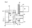
- each rotary member 26, 28 an electric motor 38 (it is only the electric motor 38 of the guide member 22 seen) is provided, which is fixed to the guide member 22 and to the support member 24.
- the electric motors 38 via spur gears 40 or via a drive gear 42 and a fixed to the rotary members 26, 28 gear 44 drive the rotary members 26, 28 adjustable in both directions of rotation.
- a cardan ring 50 which can be gimballed on cantilevers 46, 48 is provided for moment support of the carrier part 24 relative to the guide part 22.
- a wrap spring 52 is turned on (in Fig. 2 only hinted), which in the further Fig. 3 to 6 is shown in the structural design.
- the wrap spring brake 52 allows unimpeded drive of the rotary parts 26, 28 in both directions of rotation, but supports a reaction moment arising from the static and / or dynamic wheel load.
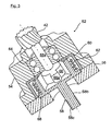
- the Fig. 3 and 4 show first the individual parts of the wrap spring 52, which consists of an outer housing 54 with a housing opening on the one hand final adapter plate 56, a divided into two sections 58a, 58b drive shaft 58, a firmly inserted into the housing 54, cup-shaped sleeve 60 and one in the sleeve 60 arranged, composed of several turns wrap 62 composed of spring steel.
- the drive shaft 58 extends through the housing 54 with adapter plate 56 and carries on the one hand the drive gear 42 of the Stirnzahnradtriebes 40 and on the other hand, a splined connector 58c, by means of which the drive shaft 58 is drivingly connected to the drive shaft of the electric motor 38, not shown, wherein at the same time the housing 54th is bolted via the adapter plate 56 to the housing of the electric motor 38.
- the section 58a of the drive shaft 58 is rotatably mounted in the housing 54 via a double-row roller bearing or ball bearing 64 and subsequently carries a closure part 66 which has two radially and diametrically outwardly projecting drivers 66a.
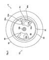
- the drivers 66a of the closing part 66 protrude into corresponding recesses 68a of a bush-shaped opening part 68, which is formed on the second section 58b of the drive shaft 58. Between the driver 66a of the shutter member 66 and the recesses 68a of the Offnervons 68 each a defined circumferential clearance is provided (see. Fig. 5 and 6 ).
- wrap spring 62 has according to the Fig. 5 and 6 at its winding ends two radially inwardly projecting arms 62 a, which project on both sides of the driver 66 a of the closer part 66 in the recesses 68 a of the opener 68. In a middle position of the closer part 66 and the opener part 68 when the wrap spring 62 is not actuated, it sits with a slight frictional engagement within the sleeve 60 (for example in the assembly position).
- an output torque M A is introduced from the drive rotary unit 38 in the wrap spring brake 52, in a, in the Fig. 6 shown release position 1 passes so that the drive torque M A is transmitted to the rotary member 26.
- the initiated drive torque M A acts according to the Fig. 6 from the portion 58b of the drive shaft 58 on the Offnerteil 68 which drives the section 58a of the drive shaft 58 and finally the drive gear 42 via the recess 68a and the driver 66a of the closure member 66.
- the according to the Fig. 6 In the recess 68a of the opener part 68 projecting arm 62a of the wrap spring 62 is rotated and causes a constriction or contraction of the wrap spring 62 so that it can rotate ineffectually within the sleeve 60. There is no frictional torque transmitted to the stationary sleeve 60.
- the same function of the wrap spring 62 is in the opposite direction of rotation, in which case the other arm 62a of the wrap spring 62 is acted upon accordingly.
- reaction torques M R from the wheel load which may affect the drive shaft 58 via the rotary members 26, 28 and the spur gear drives 40, supported by the wrap spring 62 via the housing 54, 56.
- the wire cross section of the windings of the wrap spring 62 is square or rectangular, so that seen in cross section plane friction surfaces on the inner circumference of the sleeve 60.
- the number of turns is designed according to the calculated load of the wrap spring 62 and is preferably more than two turns.
Landscapes
- Engineering & Computer Science (AREA)
- Mechanical Engineering (AREA)
- Chemical & Material Sciences (AREA)
- Combustion & Propulsion (AREA)
- Transportation (AREA)
- Vehicle Body Suspensions (AREA)
- Arrangement Or Mounting Of Propulsion Units For Vehicles (AREA)
Claims (17)
- Dispositif de réglage du carrossage et/ou du pincement d'une roue de véhicule (20), comprenant un support de roue (12), entre la partie de support (24) duquel, du côté de la roue, recevant la roue du véhicule (20), et la partie de guidage (22) duquel, du côté de l'essieu, connectée à une suspension de roue, est monté au moins un élément de réglage (26, 28) pouvant tourner autour d'un axe de rotation, qui peut être réglé au moyen d'une unité rotative d'entraînement (38) en vue du réglage du carrossage et/ou du pincement de la roue de véhicule (20), caractérisé en ce que, dans la voie d'entraînement entre l'unité rotative d'entraînement (38) et l'élément de réglage (26, 28), est monté un élément de verrouillage (52), qui, dans une position de libération (I), libère la course d'entraînement pour un transfert d'un couple d'entraînement (MA) de l'unité rotative d'entraînement (38) à l'élément de réglage (26, 28), et dans une position de verrouillage (II), produit un couple de freinage qui agit à l'encontre d'un couple de réaction (MR) orienté depuis l'élément de réglage (26, 28) vers l'unité rotative d'entraînement (38).
- Dispositif selon la revendication 1, caractérisé en ce que l'élément de verrouillage (52) est un frein à ressort hélicoïdal (52), qui s'ouvre dans le cas d'un couple d'entraînement (MA) de l'unité rotative d'entraînement (38) et qui se ferme dans le cas d'un couple de réaction (MR) de l'élément de réglage (26, 28).
- Dispositif selon la revendication 1 ou 2, caractérisé en ce que l'élément de verrouillage (52) agit à l'encontre du couple de réaction (MR) provenant de l'élément de réglage (26, 28) indépendamment de son sens de rotation.
- Dispositif selon la revendication 1, 2 ou 3, caractérisé en ce que l'élément de verrouillage (52) autorise un transfert du couple d'entraînement (MA) provenant de l'unité rotative d'entraînement (38) indépendamment de son sens de rotation.
- Dispositif selon l'une quelconque des revendications 1 à 4, caractérisé en ce que l'élément de verrouillage (52), dans le cas d'un actionnement en rotation de l'unité rotative d'entraînement (38), passe automatiquement dans sa position de libération (I).
- Dispositif selon l'une quelconque des revendications précédentes, caractérisé en ce que l'élément de verrouillage (52), dans le cas du développement d'un couple de réaction (MR) agissant depuis l'élément de réglage (26, 28) dans la direction de l'unité rotative d'entraînement (38), passe dans la position de verrouillage (II).
- Dispositif selon l'une quelconque des revendications précédentes, caractérisé en ce que le couple de freinage produit par l'élément de verrouillage (52) est égal, de préférence supérieur, au couple de réaction (MR) de l'élément de réglage (26, 28).
- Dispositif selon l'une quelconque des revendications 2 à 7, caractérisé en ce que le frein à ressort hélicoïdal (52) est monté dans l'arbre d'entraînement (58) de l'unité rotative d'entraînement.
- Dispositif selon la revendication 8, caractérisé en ce que le boîtier (54, 56) est monté sur le boîtier du moteur électrique (38), et en ce que le frein à ressort hélicoïdal (52) est disposé axialement à l'intérieur d'un palier à roulement (64) supportant l'arbre d'entraînement (58), adjacent à la roue dentée d'entraînement (42).
- Dispositif selon la revendication 8 ou 9, caractérisé en ce que l'arbre d'entraînement (58) est divisé en deux portions (58a, 58b) dans la région du frein à ressort hélicoïdal (52), lesquelles régions portent à chaque fois une partie d'ouverture (68) et une partie de fermeture (66), qui viennent en prise l'une dans l'autre par engagement positif en laissant un jeu périphérique dans les deux sens de rotation, et en ce qu'un ressort hélicoïdal (62) pénètre avec des bras (62a) saillant radialement depuis ses enroulements à chaque fois entre la partie d'ouverture (68) et la partie de fermeture (66).
- Dispositif selon la revendication 10, caractérisé en ce que le ressort hélicoïdal (62) est disposé dans une douille (60) fixée au boîtier entourant sa périphérie extérieure, dans laquelle la partie de fermeture (66) et la partie d'ouverture (68) pénètrent et coopèrent avec ses bras (62a) saillant radialement vers l'intérieur.
- Dispositif selon les revendications 10 et 11, caractérisé en ce que la partie de fermeture (66) présente, sur l'une des portions (58a) de l'arbre d'entraînement (58), deux dispositifs d'entraînement (66a) saillant radialement vers l'extérieur, qui pénètrent dans des évidements (68a) de la partie d'ouverture (68) en forme de douille fixée sur l'autre portion (58b) de l'arbre d'entraînement (58).
- Dispositif selon la revendication 11 ou 12, caractérisé en ce que le ressort hélicoïdal (62) est disposé avec précontrainte et engagement par friction dans la douille (60).
- Dispositif selon l'une quelconque des revendications 6 à 9, caractérisé en ce que le ressort hélicoïdal (62) est formé au moins par deux enroulements périphériques.
- Dispositif selon l'une quelconque des revendications 10 à 13, caractérisé en ce que le ressort hélicoïdal (62) est réalisé en section transversale sous forme carrée ou rectangulaire, avec des surfaces de friction approximativement planes et en forme d'enveloppe cylindrique.
- Dispositif selon l'une quelconque des revendications précédentes 10 à 15, caractérisé en ce que la portion (58a) de l'arbre d'entraînement (58) portant la roue dentée d'entraînement (42) et la partie de fermeture (66), et la portion (58b) de l'arbre d'entraînement (58) portant la partie d'ouverture (68) sont disposées à l'intérieur du boîtier (54) et d'une plaque d'adaptateur (56), et peuvent être connectées au boîtier du moteur électrique (38) et par le biais d'une connexion par enfichage (58c) à l'arbre d'entraînement du moteur électrique (38).
- Dispositif selon l'une quelconque des revendications précédentes, caractérisé en ce que deux éléments de réglage sont montés entre la partie de support et la partie de guidage, lesquels coopèrent de préférence avec des surfaces obliques tournées l'une vers l'autre et inclinées d'un angle défini par rapport à l'axe de rotation, les éléments de réglage pouvant être déplacés à chaque fois par le biais d'une unité d'entraînement rotative dans les deux sens de rotation.
Applications Claiming Priority (1)
| Application Number | Priority Date | Filing Date | Title |
|---|---|---|---|
| DE102009031344A DE102009031344A1 (de) | 2009-07-01 | 2009-07-01 | Vorrichtung zum Verstellen von Sturz und/oder Spur |
Publications (2)
| Publication Number | Publication Date |
|---|---|
| EP2269846A1 EP2269846A1 (fr) | 2011-01-05 |
| EP2269846B1 true EP2269846B1 (fr) | 2012-02-15 |
Family
ID=42751868
Family Applications (1)
| Application Number | Title | Priority Date | Filing Date |
|---|---|---|---|
| EP10006320A Not-in-force EP2269846B1 (fr) | 2009-07-01 | 2010-06-18 | Dispositif de réglage du carrosage et/ou de l'alignement |
Country Status (3)
| Country | Link |
|---|---|
| EP (1) | EP2269846B1 (fr) |
| AT (1) | ATE545530T1 (fr) |
| DE (1) | DE102009031344A1 (fr) |
Families Citing this family (2)
| Publication number | Priority date | Publication date | Assignee | Title |
|---|---|---|---|---|
| DE102011121874A1 (de) * | 2011-12-21 | 2013-06-27 | Audi Ag | Vorrichtung zum Stabilisieren eines Lenkgetriebes |
| DE102013008652B4 (de) | 2013-05-21 | 2016-10-13 | Audi Ag | Vorrichtung zur Sturz- und/oder Spurverstellung eines Fahrzeugrades |
Family Cites Families (6)
| Publication number | Priority date | Publication date | Assignee | Title |
|---|---|---|---|---|
| DE3928135A1 (de) * | 1988-08-31 | 1990-03-01 | Volkswagen Ag | Radaufhaengung fuer kraftfahrzeuge, insbesondere fuer personenkraftwagen |
| DE4317150C1 (de) * | 1993-05-24 | 1994-10-27 | Rentrop Hubbert & Wagner | Verstelleinrichtung zur Neigungsverstellung der Rückenlehne eines Kfz-Sitzes |
| EP1186800A1 (fr) * | 2000-09-12 | 2002-03-13 | RK Rose + Krieger GmbH & Co. KG Verbindungs- und Positioniersysteme | Moteur lineaire |
| DE102004049296A1 (de) * | 2004-10-09 | 2006-04-13 | Bayerische Motoren Werke Ag | In einem Radträger gelagerte Nabeneinheit für ein Rad eines zweispurigen Fahrzeugs |
| FR2884795B1 (fr) * | 2005-04-26 | 2007-08-10 | Michelin Soc Tech | Dispositif de suspension a carrossage variable |
| DE102008011367A1 (de) * | 2007-10-24 | 2009-04-30 | Audi Ag | Radaufhängung für Kraftfahrzeuge |
-
2009
- 2009-07-01 DE DE102009031344A patent/DE102009031344A1/de not_active Withdrawn
-
2010
- 2010-06-18 AT AT10006320T patent/ATE545530T1/de active
- 2010-06-18 EP EP10006320A patent/EP2269846B1/fr not_active Not-in-force
Also Published As
| Publication number | Publication date |
|---|---|
| EP2269846A1 (fr) | 2011-01-05 |
| ATE545530T1 (de) | 2012-03-15 |
| DE102009031344A1 (de) | 2011-01-05 |
Similar Documents
| Publication | Publication Date | Title |
|---|---|---|
| EP2429878B1 (fr) | Dispositif de réglage du carrossage et/ou de la voie | |
| EP0944781B1 (fr) | Frein electromecanique | |
| EP2914864B1 (fr) | Dispositif d'entraînement | |
| EP2999603B1 (fr) | Dispositif de réglage de carrossage et / ou de parallélisme d'une roue de véhicule | |
| WO2009141265A1 (fr) | Actionneur comprenant un système de blocage de couple de charge | |
| WO2013075818A1 (fr) | Dispositif d'accouplement pour prétensionneur de ceinture de sécurité | |
| DE102016115899A1 (de) | Lenkkrafteinstellvorrichtung und Lenkvorrichtung | |
| DE102022212923A1 (de) | Elektrische bremse für ein fahrzeug | |
| DE102014011194A1 (de) | Radträger für ein zweispuriges Kraftfahrzeug | |
| DE102020211195A1 (de) | Feedback-Aktuator für ein Lenksystem | |
| EP2607208A2 (fr) | Dispositif de stabilisation dýun mécanisme de direction | |
| EP3807556B1 (fr) | Entraînement à broche et rouleaux pour un actionneur d'une direction steer-by-wire ainsi qu'une direction steer-by-wire | |
| DE10132319A1 (de) | Radnabenantrieb | |
| EP2269846B1 (fr) | Dispositif de réglage du carrosage et/ou de l'alignement | |
| DE102018209819A1 (de) | Spindelantrieb für eine steer-by-wire-Lenkung sowie steer-by-wire-Lenkung | |
| EP3625110A1 (fr) | Direction électromécanique de véhicule à moteur | |
| EP3130490B1 (fr) | Support de roue actif pour un véhicule automobile | |
| EP1785295B1 (fr) | Barre antiroulis réglable | |
| DE102015211629A1 (de) | Hinterachslenkung für ein Kraftfahrzeug | |
| EP1502799A1 (fr) | Entraínement de moyeu de roue | |
| EP1667892B2 (fr) | Dispositif servant a superposer des mouvements de braquage pour un systeme d'assistance de direction et procede pour faire fonctionner ce dispositif | |
| DE102014100719A1 (de) | Hinterachslenkung für Kraftfahrzeuge | |
| DE102005027535A1 (de) | Überlagerungslenkung | |
| DE102021209955A1 (de) | Getriebe für ein Flurförderfahrzeug sowie Flurförderfahrzeug mit dem Getriebe | |
| EP1721807B1 (fr) | Transmission superposée pour direction à superposition |
Legal Events
| Date | Code | Title | Description |
|---|---|---|---|
| PUAI | Public reference made under article 153(3) epc to a published international application that has entered the european phase |
Free format text: ORIGINAL CODE: 0009012 |
|
| AK | Designated contracting states |
Kind code of ref document: A1 Designated state(s): AL AT BE BG CH CY CZ DE DK EE ES FI FR GB GR HR HU IE IS IT LI LT LU LV MC MK MT NL NO PL PT RO SE SI SK SM TR |
|
| AX | Request for extension of the european patent |
Extension state: BA ME RS |
|
| 17P | Request for examination filed |
Effective date: 20110705 |
|
| GRAP | Despatch of communication of intention to grant a patent |
Free format text: ORIGINAL CODE: EPIDOSNIGR1 |
|
| GRAS | Grant fee paid |
Free format text: ORIGINAL CODE: EPIDOSNIGR3 |
|
| GRAA | (expected) grant |
Free format text: ORIGINAL CODE: 0009210 |
|
| AK | Designated contracting states |
Kind code of ref document: B1 Designated state(s): AL AT BE BG CH CY CZ DE DK EE ES FI FR GB GR HR HU IE IS IT LI LT LU LV MC MK MT NL NO PL PT RO SE SI SK SM TR |
|
| REG | Reference to a national code |
Ref country code: GB Ref legal event code: FG4D Free format text: NOT ENGLISH Ref country code: CH Ref legal event code: EP |
|
| REG | Reference to a national code |
Ref country code: IE Ref legal event code: FG4D Free format text: LANGUAGE OF EP DOCUMENT: GERMAN |
|
| REG | Reference to a national code |
Ref country code: AT Ref legal event code: REF Ref document number: 545530 Country of ref document: AT Kind code of ref document: T Effective date: 20120315 |
|
| REG | Reference to a national code |
Ref country code: DE Ref legal event code: R096 Ref document number: 502010000437 Country of ref document: DE Effective date: 20120412 |
|
| REG | Reference to a national code |
Ref country code: NL Ref legal event code: VDEP Effective date: 20120215 |
|
| LTIE | Lt: invalidation of european patent or patent extension |
Effective date: 20120215 |
|
| PG25 | Lapsed in a contracting state [announced via postgrant information from national office to epo] |
Ref country code: NO Free format text: LAPSE BECAUSE OF FAILURE TO SUBMIT A TRANSLATION OF THE DESCRIPTION OR TO PAY THE FEE WITHIN THE PRESCRIBED TIME-LIMIT Effective date: 20120515 Ref country code: NL Free format text: LAPSE BECAUSE OF FAILURE TO SUBMIT A TRANSLATION OF THE DESCRIPTION OR TO PAY THE FEE WITHIN THE PRESCRIBED TIME-LIMIT Effective date: 20120215 Ref country code: HR Free format text: LAPSE BECAUSE OF FAILURE TO SUBMIT A TRANSLATION OF THE DESCRIPTION OR TO PAY THE FEE WITHIN THE PRESCRIBED TIME-LIMIT Effective date: 20120215 Ref country code: LT Free format text: LAPSE BECAUSE OF FAILURE TO SUBMIT A TRANSLATION OF THE DESCRIPTION OR TO PAY THE FEE WITHIN THE PRESCRIBED TIME-LIMIT Effective date: 20120215 Ref country code: IS Free format text: LAPSE BECAUSE OF FAILURE TO SUBMIT A TRANSLATION OF THE DESCRIPTION OR TO PAY THE FEE WITHIN THE PRESCRIBED TIME-LIMIT Effective date: 20120615 |
|
| PG25 | Lapsed in a contracting state [announced via postgrant information from national office to epo] |
Ref country code: PL Free format text: LAPSE BECAUSE OF FAILURE TO SUBMIT A TRANSLATION OF THE DESCRIPTION OR TO PAY THE FEE WITHIN THE PRESCRIBED TIME-LIMIT Effective date: 20120215 Ref country code: GR Free format text: LAPSE BECAUSE OF FAILURE TO SUBMIT A TRANSLATION OF THE DESCRIPTION OR TO PAY THE FEE WITHIN THE PRESCRIBED TIME-LIMIT Effective date: 20120516 Ref country code: PT Free format text: LAPSE BECAUSE OF FAILURE TO SUBMIT A TRANSLATION OF THE DESCRIPTION OR TO PAY THE FEE WITHIN THE PRESCRIBED TIME-LIMIT Effective date: 20120615 Ref country code: LV Free format text: LAPSE BECAUSE OF FAILURE TO SUBMIT A TRANSLATION OF THE DESCRIPTION OR TO PAY THE FEE WITHIN THE PRESCRIBED TIME-LIMIT Effective date: 20120215 Ref country code: FI Free format text: LAPSE BECAUSE OF FAILURE TO SUBMIT A TRANSLATION OF THE DESCRIPTION OR TO PAY THE FEE WITHIN THE PRESCRIBED TIME-LIMIT Effective date: 20120215 |
|
| REG | Reference to a national code |
Ref country code: IE Ref legal event code: FD4D |
|
| PG25 | Lapsed in a contracting state [announced via postgrant information from national office to epo] |
Ref country code: CY Free format text: LAPSE BECAUSE OF FAILURE TO SUBMIT A TRANSLATION OF THE DESCRIPTION OR TO PAY THE FEE WITHIN THE PRESCRIBED TIME-LIMIT Effective date: 20120215 |
|
| PG25 | Lapsed in a contracting state [announced via postgrant information from national office to epo] |
Ref country code: CZ Free format text: LAPSE BECAUSE OF FAILURE TO SUBMIT A TRANSLATION OF THE DESCRIPTION OR TO PAY THE FEE WITHIN THE PRESCRIBED TIME-LIMIT Effective date: 20120215 Ref country code: IE Free format text: LAPSE BECAUSE OF FAILURE TO SUBMIT A TRANSLATION OF THE DESCRIPTION OR TO PAY THE FEE WITHIN THE PRESCRIBED TIME-LIMIT Effective date: 20120215 Ref country code: RO Free format text: LAPSE BECAUSE OF FAILURE TO SUBMIT A TRANSLATION OF THE DESCRIPTION OR TO PAY THE FEE WITHIN THE PRESCRIBED TIME-LIMIT Effective date: 20120215 Ref country code: SI Free format text: LAPSE BECAUSE OF FAILURE TO SUBMIT A TRANSLATION OF THE DESCRIPTION OR TO PAY THE FEE WITHIN THE PRESCRIBED TIME-LIMIT Effective date: 20120215 Ref country code: SE Free format text: LAPSE BECAUSE OF FAILURE TO SUBMIT A TRANSLATION OF THE DESCRIPTION OR TO PAY THE FEE WITHIN THE PRESCRIBED TIME-LIMIT Effective date: 20120215 Ref country code: DK Free format text: LAPSE BECAUSE OF FAILURE TO SUBMIT A TRANSLATION OF THE DESCRIPTION OR TO PAY THE FEE WITHIN THE PRESCRIBED TIME-LIMIT Effective date: 20120215 Ref country code: EE Free format text: LAPSE BECAUSE OF FAILURE TO SUBMIT A TRANSLATION OF THE DESCRIPTION OR TO PAY THE FEE WITHIN THE PRESCRIBED TIME-LIMIT Effective date: 20120215 |
|
| PG25 | Lapsed in a contracting state [announced via postgrant information from national office to epo] |
Ref country code: SK Free format text: LAPSE BECAUSE OF FAILURE TO SUBMIT A TRANSLATION OF THE DESCRIPTION OR TO PAY THE FEE WITHIN THE PRESCRIBED TIME-LIMIT Effective date: 20120215 |
|
| PLBE | No opposition filed within time limit |
Free format text: ORIGINAL CODE: 0009261 |
|
| STAA | Information on the status of an ep patent application or granted ep patent |
Free format text: STATUS: NO OPPOSITION FILED WITHIN TIME LIMIT |
|
| BERE | Be: lapsed |
Owner name: AUDI A.G. Effective date: 20120630 |
|
| 26N | No opposition filed |
Effective date: 20121116 |
|
| PG25 | Lapsed in a contracting state [announced via postgrant information from national office to epo] |
Ref country code: MC Free format text: LAPSE BECAUSE OF NON-PAYMENT OF DUE FEES Effective date: 20120630 |
|
| PG25 | Lapsed in a contracting state [announced via postgrant information from national office to epo] |
Ref country code: MK Free format text: LAPSE BECAUSE OF FAILURE TO SUBMIT A TRANSLATION OF THE DESCRIPTION OR TO PAY THE FEE WITHIN THE PRESCRIBED TIME-LIMIT Effective date: 20120215 |
|
| REG | Reference to a national code |
Ref country code: DE Ref legal event code: R097 Ref document number: 502010000437 Country of ref document: DE Effective date: 20121116 |
|
| PG25 | Lapsed in a contracting state [announced via postgrant information from national office to epo] |
Ref country code: BE Free format text: LAPSE BECAUSE OF NON-PAYMENT OF DUE FEES Effective date: 20120630 Ref country code: ES Free format text: LAPSE BECAUSE OF FAILURE TO SUBMIT A TRANSLATION OF THE DESCRIPTION OR TO PAY THE FEE WITHIN THE PRESCRIBED TIME-LIMIT Effective date: 20120526 |
|
| PG25 | Lapsed in a contracting state [announced via postgrant information from national office to epo] |
Ref country code: BG Free format text: LAPSE BECAUSE OF FAILURE TO SUBMIT A TRANSLATION OF THE DESCRIPTION OR TO PAY THE FEE WITHIN THE PRESCRIBED TIME-LIMIT Effective date: 20120515 Ref country code: MT Free format text: LAPSE BECAUSE OF FAILURE TO SUBMIT A TRANSLATION OF THE DESCRIPTION OR TO PAY THE FEE WITHIN THE PRESCRIBED TIME-LIMIT Effective date: 20120215 |
|
| PG25 | Lapsed in a contracting state [announced via postgrant information from national office to epo] |
Ref country code: AL Free format text: LAPSE BECAUSE OF FAILURE TO SUBMIT A TRANSLATION OF THE DESCRIPTION OR TO PAY THE FEE WITHIN THE PRESCRIBED TIME-LIMIT Effective date: 20120215 |
|
| PG25 | Lapsed in a contracting state [announced via postgrant information from national office to epo] |
Ref country code: TR Free format text: LAPSE BECAUSE OF FAILURE TO SUBMIT A TRANSLATION OF THE DESCRIPTION OR TO PAY THE FEE WITHIN THE PRESCRIBED TIME-LIMIT Effective date: 20120215 |
|
| PG25 | Lapsed in a contracting state [announced via postgrant information from national office to epo] |
Ref country code: LU Free format text: LAPSE BECAUSE OF NON-PAYMENT OF DUE FEES Effective date: 20120618 Ref country code: SM Free format text: LAPSE BECAUSE OF FAILURE TO SUBMIT A TRANSLATION OF THE DESCRIPTION OR TO PAY THE FEE WITHIN THE PRESCRIBED TIME-LIMIT Effective date: 20120215 |
|
| PG25 | Lapsed in a contracting state [announced via postgrant information from national office to epo] |
Ref country code: HU Free format text: LAPSE BECAUSE OF FAILURE TO SUBMIT A TRANSLATION OF THE DESCRIPTION OR TO PAY THE FEE WITHIN THE PRESCRIBED TIME-LIMIT Effective date: 20100618 |
|
| REG | Reference to a national code |
Ref country code: CH Ref legal event code: PL |
|
| PG25 | Lapsed in a contracting state [announced via postgrant information from national office to epo] |
Ref country code: CH Free format text: LAPSE BECAUSE OF NON-PAYMENT OF DUE FEES Effective date: 20140630 Ref country code: LI Free format text: LAPSE BECAUSE OF NON-PAYMENT OF DUE FEES Effective date: 20140630 |
|
| REG | Reference to a national code |
Ref country code: FR Ref legal event code: PLFP Year of fee payment: 7 |
|
| REG | Reference to a national code |
Ref country code: AT Ref legal event code: MM01 Ref document number: 545530 Country of ref document: AT Kind code of ref document: T Effective date: 20150618 |
|
| PG25 | Lapsed in a contracting state [announced via postgrant information from national office to epo] |
Ref country code: AT Free format text: LAPSE BECAUSE OF NON-PAYMENT OF DUE FEES Effective date: 20150618 |
|
| REG | Reference to a national code |
Ref country code: FR Ref legal event code: PLFP Year of fee payment: 8 |
|
| REG | Reference to a national code |
Ref country code: FR Ref legal event code: PLFP Year of fee payment: 9 |
|
| PGFP | Annual fee paid to national office [announced via postgrant information from national office to epo] |
Ref country code: FR Payment date: 20210630 Year of fee payment: 12 Ref country code: DE Payment date: 20210630 Year of fee payment: 12 Ref country code: IT Payment date: 20210630 Year of fee payment: 12 |
|
| PGFP | Annual fee paid to national office [announced via postgrant information from national office to epo] |
Ref country code: GB Payment date: 20210624 Year of fee payment: 12 |
|
| REG | Reference to a national code |
Ref country code: DE Ref legal event code: R119 Ref document number: 502010000437 Country of ref document: DE |
|
| GBPC | Gb: european patent ceased through non-payment of renewal fee |
Effective date: 20220618 |
|
| PG25 | Lapsed in a contracting state [announced via postgrant information from national office to epo] |
Ref country code: FR Free format text: LAPSE BECAUSE OF NON-PAYMENT OF DUE FEES Effective date: 20220630 |
|
| PG25 | Lapsed in a contracting state [announced via postgrant information from national office to epo] |
Ref country code: GB Free format text: LAPSE BECAUSE OF NON-PAYMENT OF DUE FEES Effective date: 20220618 Ref country code: DE Free format text: LAPSE BECAUSE OF NON-PAYMENT OF DUE FEES Effective date: 20230103 |
|
| P01 | Opt-out of the competence of the unified patent court (upc) registered |
Effective date: 20230530 |
|
| PG25 | Lapsed in a contracting state [announced via postgrant information from national office to epo] |
Ref country code: IT Free format text: LAPSE BECAUSE OF NON-PAYMENT OF DUE FEES Effective date: 20220618 |