EP2607208A2 - Dispositif de stabilisation dýun mécanisme de direction - Google Patents
Dispositif de stabilisation dýun mécanisme de direction Download PDFInfo
- Publication number
- EP2607208A2 EP2607208A2 EP12008179.9A EP12008179A EP2607208A2 EP 2607208 A2 EP2607208 A2 EP 2607208A2 EP 12008179 A EP12008179 A EP 12008179A EP 2607208 A2 EP2607208 A2 EP 2607208A2
- Authority
- EP
- European Patent Office
- Prior art keywords
- electric motor
- wrap spring
- drive
- drive shaft
- steering
- Prior art date
- Legal status (The legal status is an assumption and is not a legal conclusion. Google has not performed a legal analysis and makes no representation as to the accuracy of the status listed.)
- Withdrawn
Links
Images



Classifications
-
- B—PERFORMING OPERATIONS; TRANSPORTING
- B62—LAND VEHICLES FOR TRAVELLING OTHERWISE THAN ON RAILS
- B62D—MOTOR VEHICLES; TRAILERS
- B62D5/00—Power-assisted or power-driven steering
- B62D5/001—Mechanical components or aspects of steer-by-wire systems, not otherwise provided for in this maingroup
-
- B—PERFORMING OPERATIONS; TRANSPORTING
- B62—LAND VEHICLES FOR TRAVELLING OTHERWISE THAN ON RAILS
- B62D—MOTOR VEHICLES; TRAILERS
- B62D5/00—Power-assisted or power-driven steering
- B62D5/04—Power-assisted or power-driven steering electrical, e.g. using an electric servo-motor connected to, or forming part of, the steering gear
- B62D5/0421—Electric motor acting on or near steering gear
- B62D5/0424—Electric motor acting on or near steering gear the axes of motor and final driven element of steering gear, e.g. rack, being parallel
-
- B—PERFORMING OPERATIONS; TRANSPORTING
- B62—LAND VEHICLES FOR TRAVELLING OTHERWISE THAN ON RAILS
- B62D—MOTOR VEHICLES; TRAILERS
- B62D5/00—Power-assisted or power-driven steering
- B62D5/04—Power-assisted or power-driven steering electrical, e.g. using an electric servo-motor connected to, or forming part of, the steering gear
- B62D5/0442—Conversion of rotational into longitudinal movement
- B62D5/0445—Screw drives
- B62D5/0448—Ball nuts
-
- F—MECHANICAL ENGINEERING; LIGHTING; HEATING; WEAPONS; BLASTING
- F16—ENGINEERING ELEMENTS AND UNITS; GENERAL MEASURES FOR PRODUCING AND MAINTAINING EFFECTIVE FUNCTIONING OF MACHINES OR INSTALLATIONS; THERMAL INSULATION IN GENERAL
- F16H—GEARING
- F16H25/00—Gearings comprising primarily only cams, cam-followers and screw-and-nut mechanisms
- F16H25/18—Gearings comprising primarily only cams, cam-followers and screw-and-nut mechanisms for conveying or interconverting oscillating or reciprocating motions
- F16H25/20—Screw mechanisms
- F16H25/24—Elements essential to such mechanisms, e.g. screws, nuts
- F16H25/2454—Brakes; Rotational locks
-
- F—MECHANICAL ENGINEERING; LIGHTING; HEATING; WEAPONS; BLASTING
- F16—ENGINEERING ELEMENTS AND UNITS; GENERAL MEASURES FOR PRODUCING AND MAINTAINING EFFECTIVE FUNCTIONING OF MACHINES OR INSTALLATIONS; THERMAL INSULATION IN GENERAL
- F16H—GEARING
- F16H25/00—Gearings comprising primarily only cams, cam-followers and screw-and-nut mechanisms
- F16H25/18—Gearings comprising primarily only cams, cam-followers and screw-and-nut mechanisms for conveying or interconverting oscillating or reciprocating motions
- F16H25/20—Screw mechanisms
- F16H25/24—Elements essential to such mechanisms, e.g. screws, nuts
- F16H25/2454—Brakes; Rotational locks
- F16H2025/2463—Brakes; Rotational locks using a wrap spring brake, i.e. a helical wind up spring for braking or locking
Definitions
- the present invention relates to a device for stabilizing a steering gear for motor vehicles according to the preamble of patent claim 1.
- steering actuators and front axle steering gear designed as individual actuators or central actuators are known, which are electrically driven. Because of the low efficiency, more and more of the ball screw through. On the other hand, however, the ball screw has no self-locking. This means that holding energy must always be used as soon as disturbing forces act on the ball screw from the outside.
- this magnetic brakes come into consideration, which are almost exclusively on the low-torque side, ie on the electric motor, that is, even before the gear stage, are arranged. When de-energized these brakes are closed. During operation, such magnetic brakes must be opened by means of current application, that is to be held.
- the ball screw nut In the steering actuators, respectively electric steering, the ball screw nut is always arranged concentrically to the spindle. Sometimes the spindle, but usually the ball screw nut is driven by an electric motor. The electric motor is either also arranged concentrically around the ball screw nut, often the ball screw nut is driven by gears or a toothed belt. The electric motor sits parallel to the axis next to the ball screw. Regardless of how the ball screw nut is driven, the problem of "holding the ball screw nut" arises as soon as external disturbing forces act on the ball screw. The ball screw would like to start because of the lack of self-locking easy. In the just mentioned magnetic brakes during the adjustment, that is, during steering, holding energy necessary because the brake must be kept open.
- the object of the invention is to provide a device which eliminates self-steering movements caused by return with structurally particularly simple means and works independently of any power supply.
- the invention is based on the fact that in the above-mentioned prior art, a relatively high energy requirement for holding open the friction brake during operation is required. In addition, in the above-mentioned prior art, control logic for opening and closing is required. In addition, wear is inevitable when using friction brakes.
- any external reaction torque can be braked, regardless of the direction in which it wishes to turn the electric motor. This is done by applying a wrap spring to a cylinder wall and thus preventing rotation.
- the wrap spring brake itself can be designed depending on the design, respectively space, so that the wrap spring applies either to a cylinder inner wall for braking or the wrap constricting a cylinder outer shell. Both principles of action are identical.
- a so-called closer is provided.
- the closer is connected in the case with the drive pinion, that is, all rotations that stir as a disturbance from the drive pinion forth are transmitted to the closer. This actuates the corresponding leg of the wrap spring.
- the mechanism locks immediately because the Radial wrap on a cylinder wall - self-locking and with gain factor - applies.
- the wrap spring also consists of a few simple components and has a very low weight in relation to the achievable holding force.
- there is a self-reinforcing effect by the Auflauf rational the wrap spring that is, with an increase in the torque to be braked and the braking torque increases automatically).
- the wrap spring brake works almost wear-free, since this is not a friction brake in the traditional sense.
- the output shaft of the electric motor can be made in two parts and be provided between the shaft sections cooperating with the surrounding housing wrap spring brake.
- the multiple windings wrap spring forms a simple, reliable acting component, which is freely rotatable at a torque output of the electric motor in the housing and constricting at a return torque depending on the design or expands and is thus braked in the housing. There is no energy supply required.
- the wrap spring may each have a radially projecting arm at their ends, on which arms with a small circumferential clearance a driver on one shaft section and in the opposite direction engage the flanks of a carrier comprising the arms on the other shaft section.
- the engagement surfaces of the two drivers attack in opposite directions on the wrap spring or on the arms and at the same time form a positive locking in the circumferential direction, which ensures a steering operation even in the event of failure of the wrap spring.
- the wrap spring can be arranged within a housing-fixed sleeve and project its arms radially inwards, the one, radially outwardly extending driver of a shaft portion between the arms engages and the other, recesses in a peripheral wall having driver of the other shaft portion Arms of the wrap spring embraces.
- the wrap spring brake can be arranged between a cup-shaped housing part of the electric motor and an annular adapter part adjoining the electric motor and thus represent a preassembly unit that is easy to connect to the electric motor.
- the electric motor may be arranged axially parallel to the spindle of the adjusting gear in a preferred embodiment of the invention and carry on its two-part output shaft a pinion, which is part of a spindle drive acting on the spindle nut.
- the pinion can be a spur gear drive or a toothed belt drive.
- the adjusting gear can be formed by a known ball screw whose ball screw rotatable in the steering housing, but axially guided and driven via the pinion and the threaded spindle mounted non-rotatably, but axially displaceable in the steering housing and connected to at least one track rod of the steering is.
- ball screws enable a particularly smooth and precise steering operation.
- the steering gear can be a one-sided or centrally acting steering actuator for the steered rear wheels of motor vehicles.
- the Fig. 1 roughly shows schematically a steering actuator 10 as a steering gear for steered rear wheels of motor vehicles, for example with all-wheel steering.
- the steering actuator 10 has a steering housing 12, in which a threaded spindle 14 of a ball screw 16 as a control gear is mounted non-rotatably, but axially displaceable.
- the threaded spindle 14 is pivotally connected to an outwardly guided tie rod 18.
- the steering housing 12 is fixedly connected in a manner not shown to the structure or a subframe of the motor vehicle, while the tie rod 18 is articulated to a Rad arrangementsteil the suspension of the motor vehicle.
- the ball screw nut 20 of the ball screw 16 is rotatably mounted on balls (not shown) on the threaded spindle 14 and also guided axially immovably in the steering housing 12. A rotation of the ball screw nut 20 thus causes an axial displacement of the threaded spindle 14 and a steering movement.
- the ball screw nut 20 carries a spur gear 22 which forms a gear drive 23 with a drive pinion 42, by means of which the Ball screw nut 20 is arranged from the axially parallel, fixed to the steering housing 12 electric motor 38 is driven.
- a wrap spring brake 52 is turned on (in Fig. 1 only hinted), which in the further Fig. 2 to 5 is shown in the structural design.
- the wrap spring 52 allows unimpeded drive of the ball screw nut 20 in both directions of rotation, but supports a return torque that results from side forces on the steered rear wheel.
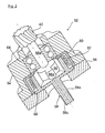
- the Fig. 2 and 3 show first the individual parts of the wrap spring 52, which consists of an outer housing 54 with a housing opening on the one hand final adapter plate 56, a divided into two sections 58a, 58b drive shaft 58, a firmly inserted into the housing 54, cup-shaped sleeve 60 and one in the sleeve 60 arranged, composed of several turns wrap 62 composed of spring steel.
- the drive shaft 58 extends through the housing 54 with adapter plate 56 and carries on the one hand the drive gear 42 of the Stirnzahnradtriebes 23 and on the other hand a splined connector 58c, by means of which the drive shaft 58 is drivingly connected to the drive shaft of the electric motor 38, not shown, wherein at the same time the housing 54th is bolted via the adapter plate 56 to the housing of the electric motor 38.
- the section 58a of the drive shaft 58 is rotatably mounted in the housing 54 via a double-row roller bearing or ball bearing 64 and subsequently carries a closure part 66 which has two radially and diametrically outwardly projecting drivers 66a.
- the drivers 66a of the closing part 66 protrude into corresponding recesses 68a of a bush-shaped opening part 68, which is formed on the second section 58b of the drive shaft 58. Between the drivers 66a of the shutter member 66 and the recesses 68a of the ⁇ ffnervons 68 each have a defined circumferential clearance is provided (see. Fig. 4 and 5 ).
- an output torque M A is introduced into the wrap spring brake 52 from the electric motor 38, which in a, in the Fig. 5 shown release position I passes so that the drive torque M A is transmitted to the ball screw nut 20.
- the initiated drive torque M A acts according to the Fig. 5 from the portion 58b of the drive shaft 58 to the opening part 68 which drives the section 58a of the drive shaft 58 and finally the drive gear 42 via the recess 68a and the driver 66a of the closing part 66.
- the according to the Fig. 5 in the recess 68a of the opener 68 protruding arm 62a of Wrap 62 is rotated and causes a constriction or contraction of the wrap 62, so that they can rotate ineffective within the sleeve 60. There is no frictional torque transmitted to the stationary sleeve 60.
- the same function of the wrap spring 62 is in the opposite direction of rotation, in which case the other arm 62a of the wrap spring 62 is acted upon accordingly.
- reaction moments M R supported by the wrap spring 62 via the sleeve 60.
- Such a reaction torque M R is about a return torque due to lateral forces on the steered rear wheel, which rests against the wrap spring 62 when the electric motor 38 is not activated.
- the reaction torque M R acts on the drive gear 42, the portion 58 a of the drive shaft 58 and the shutter member 66 on the wrap spring 62.
- the wrap spring brake 52 is thereby in its blocking position II ( Fig. 4 ), in which the driver 66a of the closer part 66 an arm 62a of the wrap spring 62 is loaded such that it widens and is braked due to the resulting friction torque.
- the drive shaft 58 with the closer part 66 can thus not be rotated within the housing 54. The same effect occurs even with a torque occurring in the opposite direction of rotation. It can therefore no impermissible steering movement occur.
- the wire cross section of the windings of the wrap spring 62 is square or rectangular, so that seen in cross section plane friction surfaces on the inner circumference of the sleeve 60.
- the number of Windings is designed according to the calculated load of the wrap spring 62 and is preferably more than two turns.
- the invention is not limited to the embodiment described.
- the steering gear 10 may also be designed as a central controller with connected to both sides tie rods or in a steer by wire steering system for the steered front wheels.
- this may directly drive the ball screw nut 20 of the ball screw 16 or other non-self-locking actuator of the steering gear via the integrated wrap spring 52.
- the output shaft 58 or its shaft section 58b can also be embodied directly as a component with the rotor of the electric motor 38.
Landscapes
- Engineering & Computer Science (AREA)
- Mechanical Engineering (AREA)
- Chemical & Material Sciences (AREA)
- Combustion & Propulsion (AREA)
- Transportation (AREA)
- General Engineering & Computer Science (AREA)
- Power Steering Mechanism (AREA)
- Steering-Linkage Mechanisms And Four-Wheel Steering (AREA)
Applications Claiming Priority (1)
| Application Number | Priority Date | Filing Date | Title |
|---|---|---|---|
| DE201110121874 DE102011121874A1 (de) | 2011-12-21 | 2011-12-21 | Vorrichtung zum Stabilisieren eines Lenkgetriebes |
Publications (2)
| Publication Number | Publication Date |
|---|---|
| EP2607208A2 true EP2607208A2 (fr) | 2013-06-26 |
| EP2607208A3 EP2607208A3 (fr) | 2016-03-23 |
Family
ID=47594199
Family Applications (1)
| Application Number | Title | Priority Date | Filing Date |
|---|---|---|---|
| EP12008179.9A Withdrawn EP2607208A3 (fr) | 2011-12-21 | 2012-12-07 | Dispositif de stabilisation d'un mécanisme de direction |
Country Status (2)
| Country | Link |
|---|---|
| EP (1) | EP2607208A3 (fr) |
| DE (1) | DE102011121874A1 (fr) |
Cited By (5)
| Publication number | Priority date | Publication date | Assignee | Title |
|---|---|---|---|---|
| EP3051180A1 (fr) * | 2015-01-29 | 2016-08-03 | Aktiebolaget SKF | Système d'engrenage |
| WO2016134746A1 (fr) * | 2015-02-24 | 2016-09-01 | Schukra Gerätebau Gmbh | Actionneur de verrou et procédé d'actionnement de verrou |
| KR20210082436A (ko) * | 2018-11-06 | 2021-07-05 | 섀플러 테크놀로지스 아게 운트 코. 카게 | 마찰 스프링 요소로 구성된 클러치 액추에이터의 사전 정의된 위치 설정 방법 |
| US11318985B2 (en) * | 2017-10-24 | 2022-05-03 | Schaeffler Technologies AG & Co. KG | Steering-by-wire actuator with locking mechanism |
| CN117261998A (zh) * | 2023-09-28 | 2023-12-22 | 中国第一汽车股份有限公司 | 后轮转向器及具有其的车辆 |
Families Citing this family (1)
| Publication number | Priority date | Publication date | Assignee | Title |
|---|---|---|---|---|
| DE102017221289B4 (de) * | 2017-11-28 | 2023-06-29 | Robert Bosch Gmbh | Risikominimaler Zustand in einem steer-by-wire-Lenksystem |
Family Cites Families (2)
| Publication number | Priority date | Publication date | Assignee | Title |
|---|---|---|---|---|
| DE102008021861A1 (de) * | 2008-05-02 | 2009-11-05 | Schaeffler Kg | Fahrwerksaktuator |
| DE102009031344A1 (de) * | 2009-07-01 | 2011-01-05 | Audi Ag | Vorrichtung zum Verstellen von Sturz und/oder Spur |
-
2011
- 2011-12-21 DE DE201110121874 patent/DE102011121874A1/de not_active Withdrawn
-
2012
- 2012-12-07 EP EP12008179.9A patent/EP2607208A3/fr not_active Withdrawn
Non-Patent Citations (1)
| Title |
|---|
| None |
Cited By (11)
| Publication number | Priority date | Publication date | Assignee | Title |
|---|---|---|---|---|
| EP3051180A1 (fr) * | 2015-01-29 | 2016-08-03 | Aktiebolaget SKF | Système d'engrenage |
| WO2016134746A1 (fr) * | 2015-02-24 | 2016-09-01 | Schukra Gerätebau Gmbh | Actionneur de verrou et procédé d'actionnement de verrou |
| CN107406011A (zh) * | 2015-02-24 | 2017-11-28 | 舒克拉机械制造有限公司 | 致动器和致动闩锁的方法 |
| US20180029508A1 (en) * | 2015-02-24 | 2018-02-01 | Schukra Gerätebau Gmbh | Actuator and method of actuating a latch |
| JP2018505814A (ja) * | 2015-02-24 | 2018-03-01 | シュクラ ゲレーテバォ ゲーエムベーハーSchukra Geraetebau Gmbh | アクチュエータおよびラッチ作動方法 |
| CN107406011B (zh) * | 2015-02-24 | 2019-08-02 | 舒克拉机械制造有限公司 | 致动器和致动闩锁的方法 |
| US10780810B2 (en) | 2015-02-24 | 2020-09-22 | Schukra Gerätebau Gmbh | Actuator and method of actuating a latch |
| US11318985B2 (en) * | 2017-10-24 | 2022-05-03 | Schaeffler Technologies AG & Co. KG | Steering-by-wire actuator with locking mechanism |
| KR20210082436A (ko) * | 2018-11-06 | 2021-07-05 | 섀플러 테크놀로지스 아게 운트 코. 카게 | 마찰 스프링 요소로 구성된 클러치 액추에이터의 사전 정의된 위치 설정 방법 |
| US11378143B2 (en) * | 2018-11-06 | 2022-07-05 | Schaeffler Technologies AG & Co. KG | Method for setting a predefined position of a clutch actuator which comprises a friction spring element |
| CN117261998A (zh) * | 2023-09-28 | 2023-12-22 | 中国第一汽车股份有限公司 | 后轮转向器及具有其的车辆 |
Also Published As
| Publication number | Publication date |
|---|---|
| DE102011121874A1 (de) | 2013-06-27 |
| EP2607208A3 (fr) | 2016-03-23 |
Similar Documents
| Publication | Publication Date | Title |
|---|---|---|
| EP3691943B1 (fr) | Actionneur de frein mechanique | |
| EP0944781B1 (fr) | Frein electromecanique | |
| EP2417001B1 (fr) | Volant de direction pour véhicule automobile à direction à superposition | |
| EP2607208A2 (fr) | Dispositif de stabilisation dýun mécanisme de direction | |
| EP1347910A1 (fr) | Dispositif electromecanique de serrage de frein | |
| DE10160717A1 (de) | Lenkung mit Umlaufgetriebe und Antrieb zum Aufprägen eines best. Handmoments am Lenkrad | |
| EP1554138A1 (fr) | Stabilisateur anti-vacillement destine au chassis d'un vehicule automobile | |
| DE10058925B4 (de) | Bremsaktuator | |
| EP1637775B1 (fr) | Actionneur linéaire avec commande manuelle en cas d'urgence | |
| DE102021213456A1 (de) | Spindelantrieb sowie Verfahren zum Betreiben eines solchen | |
| EP3807143B1 (fr) | Direction assistée par câble avec entraînement par broche | |
| EP3807556B1 (fr) | Entraînement à broche et rouleaux pour un actionneur d'une direction steer-by-wire ainsi qu'une direction steer-by-wire | |
| EP1663841A1 (fr) | Systemes de direction a limitation d'angle de braquage | |
| DE102022103978A1 (de) | Elektromotorische Aktorbaugruppe für eine elektromechanische Fahrzeugbremse und Verfahren zum Aktivieren und Deaktivieren einer Parkbremsfunktion | |
| DE10156503B4 (de) | Steuerungsverfahren zur Steuerung eines Nachstellsystems einer Scheibenbremse und Steuereinrichtung | |
| DE10106377C2 (de) | Elektromechanische Bremszuspanneinrichtung | |
| EP0913600B1 (fr) | Dispositif pour la production d'un mouvement rotatif ou linéaire | |
| DE10135141A1 (de) | Starter | |
| EP4238853A1 (fr) | Colonne de direction par câble pour un véhicule automobile | |
| DE10015922A1 (de) | Lenksystem | |
| EP2269846B1 (fr) | Dispositif de réglage du carrosage et/ou de l'alignement | |
| DE102015211629A1 (de) | Hinterachslenkung für ein Kraftfahrzeug | |
| EP1667892B2 (fr) | Dispositif servant a superposer des mouvements de braquage pour un systeme d'assistance de direction et procede pour faire fonctionner ce dispositif | |
| DE102016213560A1 (de) | Vorrichtung und Verfahren zur Betätigung einer Parksperre eines Getriebes eines Kraftfahrzeuges | |
| WO2025261857A1 (fr) | Dispositif de direction |
Legal Events
| Date | Code | Title | Description |
|---|---|---|---|
| AK | Designated contracting states |
Kind code of ref document: A2 Designated state(s): AL AT BE BG CH CY CZ DE DK EE ES FI FR GB GR HR HU IE IS IT LI LT LU LV MC MK MT NL NO PL PT RO RS SE SI SK SM TR |
|
| AX | Request for extension of the european patent |
Extension state: BA ME |
|
| PUAI | Public reference made under article 153(3) epc to a published international application that has entered the european phase |
Free format text: ORIGINAL CODE: 0009012 |
|
| PUAL | Search report despatched |
Free format text: ORIGINAL CODE: 0009013 |
|
| AK | Designated contracting states |
Kind code of ref document: A3 Designated state(s): AL AT BE BG CH CY CZ DE DK EE ES FI FR GB GR HR HU IE IS IT LI LT LU LV MC MK MT NL NO PL PT RO RS SE SI SK SM TR |
|
| AX | Request for extension of the european patent |
Extension state: BA ME |
|
| RIC1 | Information provided on ipc code assigned before grant |
Ipc: F16H 25/24 20060101ALI20160215BHEP Ipc: B62D 7/15 20060101AFI20160215BHEP Ipc: B62D 5/04 20060101ALI20160215BHEP |
|
| STAA | Information on the status of an ep patent application or granted ep patent |
Free format text: STATUS: THE APPLICATION HAS BEEN WITHDRAWN |
|
| 18W | Application withdrawn |
Effective date: 20160610 |