EP2269871B1 - Pince support pour le montage de grilles de véhicule - Google Patents
Pince support pour le montage de grilles de véhicule Download PDFInfo
- Publication number
- EP2269871B1 EP2269871B1 EP10380088A EP10380088A EP2269871B1 EP 2269871 B1 EP2269871 B1 EP 2269871B1 EP 10380088 A EP10380088 A EP 10380088A EP 10380088 A EP10380088 A EP 10380088A EP 2269871 B1 EP2269871 B1 EP 2269871B1
- Authority
- EP
- European Patent Office
- Prior art keywords
- plate
- compensator
- allowance
- notch
- reinforcement beam
- Prior art date
- Legal status (The legal status is an assumption and is not a legal conclusion. Google has not performed a legal analysis and makes no representation as to the accuracy of the status listed.)
- Not-in-force
Links
- 230000002787 reinforcement Effects 0.000 claims abstract description 61
- 238000004873 anchoring Methods 0.000 claims abstract description 7
- 239000000463 material Substances 0.000 claims abstract description 5
- 239000003973 paint Substances 0.000 description 3
- 230000000284 resting effect Effects 0.000 description 3
- 230000007797 corrosion Effects 0.000 description 2
- 238000005260 corrosion Methods 0.000 description 2
- 238000010422 painting Methods 0.000 description 2
- 238000003466 welding Methods 0.000 description 2
- 238000005452 bending Methods 0.000 description 1
- 230000005540 biological transmission Effects 0.000 description 1
- 230000000694 effects Effects 0.000 description 1
- 230000014759 maintenance of location Effects 0.000 description 1
- 230000003014 reinforcing effect Effects 0.000 description 1
- 238000000926 separation method Methods 0.000 description 1
Images



Classifications
-
- B—PERFORMING OPERATIONS; TRANSPORTING
- B60—VEHICLES IN GENERAL
- B60R—VEHICLES, VEHICLE FITTINGS, OR VEHICLE PARTS, NOT OTHERWISE PROVIDED FOR
- B60R9/00—Supplementary fittings on vehicle exterior for carrying loads, e.g. luggage, sports gear or the like
- B60R9/04—Carriers associated with vehicle roof
-
- F—MECHANICAL ENGINEERING; LIGHTING; HEATING; WEAPONS; BLASTING
- F16—ENGINEERING ELEMENTS AND UNITS; GENERAL MEASURES FOR PRODUCING AND MAINTAINING EFFECTIVE FUNCTIONING OF MACHINES OR INSTALLATIONS; THERMAL INSULATION IN GENERAL
- F16B—DEVICES FOR FASTENING OR SECURING CONSTRUCTIONAL ELEMENTS OR MACHINE PARTS TOGETHER, e.g. NAILS, BOLTS, CIRCLIPS, CLAMPS, CLIPS OR WEDGES; JOINTS OR JOINTING
- F16B21/00—Means for preventing relative axial movement of a pin, spigot, shaft or the like and a member surrounding it; Stud-and-socket releasable fastenings
- F16B21/06—Releasable fastening devices with snap-action
- F16B21/07—Releasable fastening devices with snap-action in which the socket has a resilient part
- F16B21/073—Releasable fastening devices with snap-action in which the socket has a resilient part the socket having a resilient part on its inside
- F16B21/075—Releasable fastening devices with snap-action in which the socket has a resilient part the socket having a resilient part on its inside the socket having resilient parts on its inside and outside
-
- F—MECHANICAL ENGINEERING; LIGHTING; HEATING; WEAPONS; BLASTING
- F16—ENGINEERING ELEMENTS AND UNITS; GENERAL MEASURES FOR PRODUCING AND MAINTAINING EFFECTIVE FUNCTIONING OF MACHINES OR INSTALLATIONS; THERMAL INSULATION IN GENERAL
- F16B—DEVICES FOR FASTENING OR SECURING CONSTRUCTIONAL ELEMENTS OR MACHINE PARTS TOGETHER, e.g. NAILS, BOLTS, CIRCLIPS, CLAMPS, CLIPS OR WEDGES; JOINTS OR JOINTING
- F16B5/00—Joining sheets or plates, e.g. panels, to one another or to strips or bars parallel to them
- F16B5/02—Joining sheets or plates, e.g. panels, to one another or to strips or bars parallel to them by means of fastening members using screw-thread
- F16B5/0216—Joining sheets or plates, e.g. panels, to one another or to strips or bars parallel to them by means of fastening members using screw-thread the position of the plates to be connected being adjustable
- F16B5/0233—Joining sheets or plates, e.g. panels, to one another or to strips or bars parallel to them by means of fastening members using screw-thread the position of the plates to be connected being adjustable allowing for adjustment perpendicular to the plane of the plates
-
- F—MECHANICAL ENGINEERING; LIGHTING; HEATING; WEAPONS; BLASTING
- F16—ENGINEERING ELEMENTS AND UNITS; GENERAL MEASURES FOR PRODUCING AND MAINTAINING EFFECTIVE FUNCTIONING OF MACHINES OR INSTALLATIONS; THERMAL INSULATION IN GENERAL
- F16B—DEVICES FOR FASTENING OR SECURING CONSTRUCTIONAL ELEMENTS OR MACHINE PARTS TOGETHER, e.g. NAILS, BOLTS, CIRCLIPS, CLAMPS, CLIPS OR WEDGES; JOINTS OR JOINTING
- F16B5/00—Joining sheets or plates, e.g. panels, to one another or to strips or bars parallel to them
- F16B5/12—Fastening strips or bars to sheets or plates, e.g. rubber strips, decorative strips for motor vehicles, by means of clips
- F16B5/121—Fastening strips or bars to sheets or plates, e.g. rubber strips, decorative strips for motor vehicles, by means of clips fastened over the edge(s) of the sheet(s) or plate(s)
-
- F—MECHANICAL ENGINEERING; LIGHTING; HEATING; WEAPONS; BLASTING
- F16—ENGINEERING ELEMENTS AND UNITS; GENERAL MEASURES FOR PRODUCING AND MAINTAINING EFFECTIVE FUNCTIONING OF MACHINES OR INSTALLATIONS; THERMAL INSULATION IN GENERAL
- F16B—DEVICES FOR FASTENING OR SECURING CONSTRUCTIONAL ELEMENTS OR MACHINE PARTS TOGETHER, e.g. NAILS, BOLTS, CIRCLIPS, CLAMPS, CLIPS OR WEDGES; JOINTS OR JOINTING
- F16B5/00—Joining sheets or plates, e.g. panels, to one another or to strips or bars parallel to them
- F16B5/12—Fastening strips or bars to sheets or plates, e.g. rubber strips, decorative strips for motor vehicles, by means of clips
- F16B5/123—Auxiliary fasteners specially designed for this purpose
Definitions
- the present invention refers to a support clamp for mounting vehicle racks and more specifically for mounting racks which include an allowance compensator, as a means to safely fasten the rack to the reinforcement beam(s) of the flanks of a vehicle roof, through holes in said beams.
- the clamp of the invention is designed as a means to guarantee the centering of the allowance compensator on each one of the holes of the reinforcement beams.
- anchors which comprise a fixing screw and an allowance compensator.
- the fixing screw is inserted through opposing holes of longitudinal bars of the rack, of the roof sheet and of the reinforcement beam and rests outwardly and is tightened against the bar of the rack and the reinforcement beam.
- the allowance compensator is arranged between the roof sheet and the reinforcement beam thereof, resting and tightening against these components.
- the purpose of the allowance compensator is to maintain a constant relief in the rack support on the roof sheet and absorb dimensional allowances generated by the mounting between the roof sheet and the reinforcement beam thereof, and to enable a controlled transmission of the tightening torque between the different components: rack, roof sheet and reinforcement beam.
- An anchor with this constitution is described in the utility model 200800910 of the same applicants.
- Another example of an allowance compensator is described in DE 19542109 A1 .
- the problem of the anchor with the constitution described is that its mounting on the vehicle roof has to be carried out in the vehicle assembly line. To that end, the operator with the appropriate tool, once the reinforcement beam has been mounted, assembles the compensator from the vehicle interior, with the space problems that this entails and fundamentally with risks of lack of precision in the mounting.
- the allowance compensator comprises an upper bushing and a lower nut, and also a cage retainer of the nut on the reinforcement beam, coinciding with each one of the holes of said beam.
- the nut of the allowance compensator is fixed to the reinforcement beam, for example by welding, before the mounting of said beam on the vehicle roof.
- the fixing of the cage must be performed so that it offers a correct centering of the allowance compensator, with respect to the holes of the reinforcement beam.
- the allowance compensator is in contact with the reinforcement beam, so that when said beam is submerged with the allowance compensator in the paint bath, both components are joined and when they are detached later there can be an area or spot without paint, where there will be a corrosion effect.
- the heat caused by the welding of the cage to the reinforcement beam can produce deformations on said bar, creating an allowance problem and a bad adjustment in the mounting of the different components.
- the object of the present invention is a support clamp for the mounting of racks on vehicle roofs, constituted so that it enables to help in the centering of the allowance compensator, with respect to the holes of the reinforcement beam, and at the same time it avoids contact between said beam and the allowance compensator, to prevent both elements from being joined through the paint bath they receive, thus avoiding the later corrosion of the vehicle, when these two components are detached.
- the support clamp is constituted by a plastic material plate featuring, from one of its edges, a notch with the appropriate dimensions to enable the allowance compensator to pass through it, while from the opposite edge, said plate extends into a pull-tab, which will serve as a lever or action means to facilitate the mounting and dismounting of the clamp in the reinforcement beam, in a position transversal to it.
- the plate constituting the clamp of the invention comprises means for its positioning and anchorage to the reinforcement beams, in transversal position and under them, with the notch coinciding with the contour of one of the reinforcement beam holes.
- the plate also has means to fasten and center the allowance compensator with respect to the reinforcement beam hole, so that it is separated from said beam.
- pull-tab forms an angle higher than 180° with the upper surface of the plate, to act as an action lever in the clamp mounting and dismounting phase on the beam.
- This tab has transversal ribs on its outer surface which will facilitate its gripping and handling during the clamp mounting and dismounting phases.
- the notch of the plate forming the clamp has a circular contour, its diameter being slightly larger than the outer contour of the allowance compensator, and leading through a passage thinner than the diameter of said circular contour. From the circular contour of the notch there protrude radial teeth having certain downward inclination and delimiting a smaller circular contour than the external one of the allowance compensator, determining the centering means and the fastening means of said compensator.
- the plate forming the clamp is also provided, from its free longitudinal edges and in a position adjacent to the pull-tab, with aligned lateral notches.
- the positioning and anchoring means of the plate to the reinforcement beam consist of two bended pins, which perpendicularly protrude from the plate between the lateral notches and the root or beginning of the aforementioned pull-tabs, and in a series of straight pins perpendicularly protruding also from the plate, on the same side as the bended pins, in a position adjacent to the circular edge of the plate notch.
- the straight pins delimit an outer contour which has an approximately equal diameter to that of the reinforcement beam holes.
- the bended pins have a section parallel to the plate, which is guided towards a direction opposite to the pull-tab.
- These bended pins can be Z-shaped, with end sections perpendicular to the plate and with the intermediate section parallel thereto, and approximately the same height as the thickness of the reinforcement beam.
- the straight pins will have a larger height than the thickness of the reinforcement beam and will end in an outer flange or flaring protruding on said bar.
- the plate also has, from the bottom of the notch, two through cutting lines, directed towards the pull-tab, which facilitate the bending of the plate with respect to the straight pins.
- Figure 1 shows a perspective view of a support clamp, for the mounting of vehicle racks, comprising a plastic material plate 1, with approximately rectangular contour, featuring from one of its edges a notch 2, which includes a circular contour 3, the diameter of which is slightly larger than the external one of the allowance compensator, and a slightly throttled outlet 4, with a slightly smaller diameter than the external one of the allowance compensator. From the opposite edge of the plate 1 there protrudes a pull-tab 5 which forms with the outer surface of the plate an angle higher than 180° and which has transversal ribs 6 on its outer surface to facilitate the operation on said tab.
- the plate 1 From its longitudinal edges, the plate 1 has opposite notches 7, and between said notches and the tab 5 there protrude, above the plate, two bended pins 8, preferably Z-shaped pins, with end sections 9 which are perpendicular to the plate 1 and an intermediate section 10 which is parallel to said plate and is separated from it by a distance which is approximately equal to the reinforcement beam thickness.
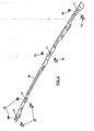
- Figure 2 shows a reinforcement beam, including a series of holes 17, and coinciding with each one of them there will be mounted a support clamp, which is indicated by reference number 18, and an allowance compensator 19.
- the support clamp 18 is mounted in a transversal position on the reinforcement beam 16, so that the bended pins 8 of the support clamp encircle the beam through one of its longitudinal edges, partially protruding through the corresponding hole 17 of the straight pins 12, resting the rear flange 13 against said beam.
- the circular contour 3 of the notch 2 is located in a position coinciding with the reinforcement beam hole 17 contour.
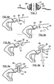
- the mounting of the support clamp 18 on the beam 16 is carried out as shown in figures 4a to 4d , progressively inserting the plate 1 under the beam 16, with deformation of the bended pins 18, until the corresponding section of the beam 16 is braced between the bended pins 8, the straight pins 12 and the flange 3' around the edge 3, between the straight pins 12, and from which there protrude teeth 11, as shown in figure 4d .
- the necessary deformation of the plate 1 and pins 8 is attained by means of action on the pull-tab 5.
- the allowance compensator 20 is mounted as shown in figure 5 , following the sequences represented in figures 6a to 6c , facing the threaded bushing 21 of the allowance compensator to the hole 17 of the reinforcement beam 6 and downwardly displacing thereafter said bushing until it goes through the circular contour 3 of the notch 2, tightened between the teeth 11, which retain it, preventing its accidental exit.
- the nut 22 of the allowance compensator will rest against the flanges 15, figure 1 , of the plate 1, preventing it from resting directly on its surface.
- Figure 7 shows how the teeth 11 retain the bushing 21 of the allowance compensator, with the nut 22 separated from the surface of the reinforcement beam 16.
- the reinforcement beam 16 is mounted, along the vehicle roof flanks, under the roof sheet 24, coinciding with the hole 25 thereof.
- the support clamp 18 is dismounted, following an inverse sequence to the one described with reference to figures 4a to 4d , then lifting the bushing 21 of the allowance compensator, through the rotation thereof with respect to the nut 22, as indicated by arrows in figure 8c .
- the rack is placed, in such a way that the beam holes 26 thereof face the bushing 21 of the allowance compensator, to insert after that, from the vehicle interior, the nut 27 which is screwed to the integral nut 28 of the rack beams 26, being the nut 22 pressed downwards against the reinforcement beam 16 and upwards, through the plastic material washer 29, against the vehicle roof 24, all of which is represented in figure 8c .
- the teeth 11 constitute the positioning and fastening means of the allowance compensator, while the bended pins 8 and the straight pins 12 are positioning and anchoring means of the clamp to the reinforcement beams.
- the pivots 15 serve as separation elements between the allowance compensator nut and the reinforcement beam.
- the reinforcement beam 16 has, in longitudinal alignment and at both sides of each hole 17 of the reinforcement beam 16; two wings 30 that prevent the rotation of the nut 22 of the allowance compensator.
Landscapes
- Engineering & Computer Science (AREA)
- General Engineering & Computer Science (AREA)
- Mechanical Engineering (AREA)
- Fittings On The Vehicle Exterior For Carrying Loads, And Devices For Holding Or Mounting Articles (AREA)
- Vehicle Body Suspensions (AREA)
- Connection Of Plates (AREA)
- Insertion Pins And Rivets (AREA)
Claims (9)
- Ferrure-support pour le montage de supports de véhicules, conçue pour garantir le centrage d'un correcteur de jeu dans chacun des orifices des barres de renforcement des flancs du toit du véhicule où le support est fixé, caractérisée en ce qu'elle comprend : une plaque en matière plastique présentant, à partir de l'un de ses bords, une entaille aux dimensions adéquates pour permettre au compensateur de jeu de passer à travers, tandis que depuis le bord opposé, cette plaque s'étend pour former une languette de traction ; cette plaque étant pourvue de moyens de positionnement et de fixation aux barres de renforcement, en position transversale et au-dessous de ces dernières; avec l'entaille coïncidant avec le contour de l'un des orifices des barres de renforcement, et de moyens pour fixer et centrer le compensateur de jeu, par rapport à l'orifice de la barre de renforcement, tout en les tenant séparés.
- Ferrure-support selon la revendication 1, caractérisée en ce que cette entaille présente une partie inférieure au contour circulaire, son diamètre étant légèrement supérieur à celui du contour extérieur du compensateur de jeu, et une entaille dont la largeur est inférieure au diamètre de ce contour circulaire, qui ressort, dans le sens radial, de la partie inférieure des dents de l'entaille, qui présente une inclinaison vers le bas, définissant un contour circulaire inférieur au contour externe du compensateur de jeu, pour configurer le positionnement et les moyens de fixation de ce compensateur.
- Ferrure-support selon la revendication 1, caractérisée en ce que la plaque susmentionnée présente un contour approximativement rectangulaire, amenant l'entaille susmentionnée à travers l'un des petits bords de cette plaque, tandis qu'une languette de traction ressort du petit bord opposé, la plaque étant dotée, depuis ses bords longitudinaux et dans une position adjacente à la languette de traction, d'entailles latérales alignées transversalement.
- Ferrure-support, selon la revendication 1, caractérisée en ce que les moyens de positionnement et de fixation de la plaque à la barre de renforcement consistent en deux broches incurvées, qui ressortent perpendiculairement de la plaque, entre les entailles latérales et la naissance ou le commencement de la languette de traction, et en une série de broches droites qui ressortent perpendiculairement de la plaque, du même côté que les broches incurvées, dans une position adjacente au bord circulaire de l'entaille susmentionnée, et qui définissent un contour extérieur, présentant un diamètre approximativement égal à celui des orifices de la barre de renforcement ; dont les broches incurvées présentent une section parallèle à la plaque, qui est orientée vers une direction opposée à la languette de traction.
- Ferrure-support selon la revendication 4, caractérisée en ce que les broches incurvées présentent une forme en Z, avec les sections extrêmes perpendiculaires à la plaque, une section intermédiaire parallèle à cette plaque et ayant environ la même hauteur que la grosseur de la barre de renforcement.
- Ferrure-support selon la revendication 4, caractérisée en ce que les broches droites présentent une hauteur plus grande que la grosseur de la barre de renforcement et ces broches droites finissent en une collerette ou partie évasée externe, qui ressort sur cette barre de renforcement.
- Ferrure-support selon la revendication 1, caractérisée en ce que de la surface supérieure de la plaque ressortent une série de pivots séparateurs, autour de l'entaille, pour le support de la barre de renforcement.
- Ferrure-support selon la revendication 1, caractérisée en ce que la plaque est pourvue, depuis la partie inférieure de l'entaille, de deux lignes de coupe passantes, orientées vers la languette de traction.
- Ferrure-support selon la revendication 1 ou 3, caractérisée en ce que la languette de traction forme un angle avec la surface supérieure de la plaque de plus de 180°.
Applications Claiming Priority (1)
| Application Number | Priority Date | Filing Date | Title |
|---|---|---|---|
| ES200930232U ES1070737Y (es) | 2009-07-01 | 2009-07-01 | Pinza soporte para el montaje de bacas de vehiculos |
Publications (2)
| Publication Number | Publication Date |
|---|---|
| EP2269871A1 EP2269871A1 (fr) | 2011-01-05 |
| EP2269871B1 true EP2269871B1 (fr) | 2011-08-10 |
Family
ID=41136612
Family Applications (1)
| Application Number | Title | Priority Date | Filing Date |
|---|---|---|---|
| EP10380088A Not-in-force EP2269871B1 (fr) | 2009-07-01 | 2010-06-30 | Pince support pour le montage de grilles de véhicule |
Country Status (3)
| Country | Link |
|---|---|
| EP (1) | EP2269871B1 (fr) |
| AT (1) | ATE519628T1 (fr) |
| ES (2) | ES1070737Y (fr) |
Family Cites Families (2)
| Publication number | Priority date | Publication date | Assignee | Title |
|---|---|---|---|---|
| DE19542109C2 (de) * | 1994-11-24 | 2001-08-30 | Volkswagen Ag | Befestigungsanordnung einer Reling auf einem Fahrzeugdach |
| FI122331B (fi) | 2006-06-30 | 2011-12-15 | Teknosavo Oy | Menetelmä puun tilavuuden mittaamiseen ja laadun tarkkailuun |
-
2009
- 2009-07-01 ES ES200930232U patent/ES1070737Y/es not_active Expired - Fee Related
-
2010
- 2010-06-30 AT AT10380088T patent/ATE519628T1/de not_active IP Right Cessation
- 2010-06-30 ES ES10380088T patent/ES2370982T3/es active Active
- 2010-06-30 EP EP10380088A patent/EP2269871B1/fr not_active Not-in-force
Also Published As
| Publication number | Publication date |
|---|---|
| ATE519628T1 (de) | 2011-08-15 |
| ES2370982T3 (es) | 2011-12-26 |
| ES1070737Y (es) | 2010-01-18 |
| ES1070737U (es) | 2009-10-21 |
| EP2269871A1 (fr) | 2011-01-05 |
Similar Documents
| Publication | Publication Date | Title |
|---|---|---|
| EP2174836A1 (fr) | Ancrage pour monter des galeries de toit de véhicule | |
| US8262332B2 (en) | Connecting element, in particular a speed nut | |
| KR101424034B1 (ko) | 슬래브 거푸집 시스템 | |
| EP2558732B1 (fr) | Dispositif de suspension pour véhicule | |
| US6953208B2 (en) | Drain support plate/under-deck clamp | |
| EP0048574B1 (fr) | Dispositif de fixation pour supports | |
| US10787826B2 (en) | Support head, ceiling support, and ceiling formwork having such a ceiling support | |
| WO2017027187A1 (fr) | Système de montage de modules photovoltaïques | |
| SE537673C2 (sv) | Låsbrickanordning | |
| US7603814B1 (en) | Decking system hanger | |
| EP2538000B1 (fr) | Procédé permettant de corriger l'ovalisation dans des tours de turbine éolienne | |
| EP3430273B1 (fr) | Ensemble de pince en u | |
| EP1852562A2 (fr) | Support pour équipement de toiture, système de protection de toit et procédé de montage d'une protection de toit | |
| US20040094681A1 (en) | Bracket element | |
| EP2269871B1 (fr) | Pince support pour le montage de grilles de véhicule | |
| CN101927790A (zh) | 连接安排 | |
| US7641012B2 (en) | Module-locating fastener and method of mounting on a vehicle chassis | |
| EP2113421B1 (fr) | Ancrage pour galerie de toit de véhicule | |
| JP2006188877A (ja) | 屋根上取付け金具 | |
| EP3327218A1 (fr) | Renfort en diagonale pour structures de support de coffrages de plancher et procédé de montage associé | |
| GB2629418A (en) | Fastener lock | |
| DE102009008220A1 (de) | Befestigungselement für die strukturversteifte Befestigung eines Kraftfahrzeugbauteils | |
| US12194555B2 (en) | Method for making screw hole | |
| GB2051911A (en) | Securing an Outer Cladding to a Roof or Wall Structure and Hook Bolt Therefor | |
| RU64973U1 (ru) | Устройство для удержания привариваемой полосы в заданном положении |
Legal Events
| Date | Code | Title | Description |
|---|---|---|---|
| PUAI | Public reference made under article 153(3) epc to a published international application that has entered the european phase |
Free format text: ORIGINAL CODE: 0009012 |
|
| AK | Designated contracting states |
Kind code of ref document: A1 Designated state(s): AL AT BE BG CH CY CZ DE DK EE ES FI FR GB GR HR HU IE IS IT LI LT LU LV MC MK MT NL NO PL PT RO SE SI SK SM TR |
|
| AX | Request for extension of the european patent |
Extension state: BA ME RS |
|
| 17P | Request for examination filed |
Effective date: 20101214 |
|
| RIC1 | Information provided on ipc code assigned before grant |
Ipc: F16B 37/04 20060101ALI20110112BHEP Ipc: B60R 9/04 20060101AFI20110112BHEP Ipc: B60R 9/058 20060101ALI20110112BHEP Ipc: F16B 5/02 20060101ALI20110112BHEP |
|
| GRAP | Despatch of communication of intention to grant a patent |
Free format text: ORIGINAL CODE: EPIDOSNIGR1 |
|
| GRAS | Grant fee paid |
Free format text: ORIGINAL CODE: EPIDOSNIGR3 |
|
| GRAA | (expected) grant |
Free format text: ORIGINAL CODE: 0009210 |
|
| AK | Designated contracting states |
Kind code of ref document: B1 Designated state(s): AL AT BE BG CH CY CZ DE DK EE ES FI FR GB GR HR HU IE IS IT LI LT LU LV MC MK MT NL NO PL PT RO SE SI SK SM TR |
|
| REG | Reference to a national code |
Ref country code: GB Ref legal event code: FG4D |
|
| REG | Reference to a national code |
Ref country code: CH Ref legal event code: EP |
|
| REG | Reference to a national code |
Ref country code: IE Ref legal event code: FG4D |
|
| REG | Reference to a national code |
Ref country code: DE Ref legal event code: R096 Ref document number: 602010000139 Country of ref document: DE Effective date: 20111006 |
|
| REG | Reference to a national code |
Ref country code: NL Ref legal event code: VDEP Effective date: 20110810 |
|
| REG | Reference to a national code |
Ref country code: ES Ref legal event code: FG2A Ref document number: 2370982 Country of ref document: ES Kind code of ref document: T3 Effective date: 20111226 |
|
| LTIE | Lt: invalidation of european patent or patent extension |
Effective date: 20110810 |
|
| PG25 | Lapsed in a contracting state [announced via postgrant information from national office to epo] |
Ref country code: PT Free format text: LAPSE BECAUSE OF FAILURE TO SUBMIT A TRANSLATION OF THE DESCRIPTION OR TO PAY THE FEE WITHIN THE PRESCRIBED TIME-LIMIT Effective date: 20111212 Ref country code: SE Free format text: LAPSE BECAUSE OF FAILURE TO SUBMIT A TRANSLATION OF THE DESCRIPTION OR TO PAY THE FEE WITHIN THE PRESCRIBED TIME-LIMIT Effective date: 20110810 Ref country code: NO Free format text: LAPSE BECAUSE OF FAILURE TO SUBMIT A TRANSLATION OF THE DESCRIPTION OR TO PAY THE FEE WITHIN THE PRESCRIBED TIME-LIMIT Effective date: 20111110 Ref country code: IS Free format text: LAPSE BECAUSE OF FAILURE TO SUBMIT A TRANSLATION OF THE DESCRIPTION OR TO PAY THE FEE WITHIN THE PRESCRIBED TIME-LIMIT Effective date: 20111210 Ref country code: HR Free format text: LAPSE BECAUSE OF FAILURE TO SUBMIT A TRANSLATION OF THE DESCRIPTION OR TO PAY THE FEE WITHIN THE PRESCRIBED TIME-LIMIT Effective date: 20110810 Ref country code: NL Free format text: LAPSE BECAUSE OF FAILURE TO SUBMIT A TRANSLATION OF THE DESCRIPTION OR TO PAY THE FEE WITHIN THE PRESCRIBED TIME-LIMIT Effective date: 20110810 Ref country code: FI Free format text: LAPSE BECAUSE OF FAILURE TO SUBMIT A TRANSLATION OF THE DESCRIPTION OR TO PAY THE FEE WITHIN THE PRESCRIBED TIME-LIMIT Effective date: 20110810 Ref country code: LT Free format text: LAPSE BECAUSE OF FAILURE TO SUBMIT A TRANSLATION OF THE DESCRIPTION OR TO PAY THE FEE WITHIN THE PRESCRIBED TIME-LIMIT Effective date: 20110810 |
|
| REG | Reference to a national code |
Ref country code: AT Ref legal event code: MK05 Ref document number: 519628 Country of ref document: AT Kind code of ref document: T Effective date: 20110810 |
|
| PG25 | Lapsed in a contracting state [announced via postgrant information from national office to epo] |
Ref country code: GR Free format text: LAPSE BECAUSE OF FAILURE TO SUBMIT A TRANSLATION OF THE DESCRIPTION OR TO PAY THE FEE WITHIN THE PRESCRIBED TIME-LIMIT Effective date: 20111111 Ref country code: PL Free format text: LAPSE BECAUSE OF FAILURE TO SUBMIT A TRANSLATION OF THE DESCRIPTION OR TO PAY THE FEE WITHIN THE PRESCRIBED TIME-LIMIT Effective date: 20110810 Ref country code: CY Free format text: LAPSE BECAUSE OF FAILURE TO SUBMIT A TRANSLATION OF THE DESCRIPTION OR TO PAY THE FEE WITHIN THE PRESCRIBED TIME-LIMIT Effective date: 20110810 Ref country code: AT Free format text: LAPSE BECAUSE OF FAILURE TO SUBMIT A TRANSLATION OF THE DESCRIPTION OR TO PAY THE FEE WITHIN THE PRESCRIBED TIME-LIMIT Effective date: 20110810 Ref country code: SI Free format text: LAPSE BECAUSE OF FAILURE TO SUBMIT A TRANSLATION OF THE DESCRIPTION OR TO PAY THE FEE WITHIN THE PRESCRIBED TIME-LIMIT Effective date: 20110810 Ref country code: LV Free format text: LAPSE BECAUSE OF FAILURE TO SUBMIT A TRANSLATION OF THE DESCRIPTION OR TO PAY THE FEE WITHIN THE PRESCRIBED TIME-LIMIT Effective date: 20110810 |
|
| PG25 | Lapsed in a contracting state [announced via postgrant information from national office to epo] |
Ref country code: BE Free format text: LAPSE BECAUSE OF FAILURE TO SUBMIT A TRANSLATION OF THE DESCRIPTION OR TO PAY THE FEE WITHIN THE PRESCRIBED TIME-LIMIT Effective date: 20110810 |
|
| PG25 | Lapsed in a contracting state [announced via postgrant information from national office to epo] |
Ref country code: CZ Free format text: LAPSE BECAUSE OF FAILURE TO SUBMIT A TRANSLATION OF THE DESCRIPTION OR TO PAY THE FEE WITHIN THE PRESCRIBED TIME-LIMIT Effective date: 20110810 Ref country code: SK Free format text: LAPSE BECAUSE OF FAILURE TO SUBMIT A TRANSLATION OF THE DESCRIPTION OR TO PAY THE FEE WITHIN THE PRESCRIBED TIME-LIMIT Effective date: 20110810 |
|
| PG25 | Lapsed in a contracting state [announced via postgrant information from national office to epo] |
Ref country code: RO Free format text: LAPSE BECAUSE OF FAILURE TO SUBMIT A TRANSLATION OF THE DESCRIPTION OR TO PAY THE FEE WITHIN THE PRESCRIBED TIME-LIMIT Effective date: 20110810 Ref country code: EE Free format text: LAPSE BECAUSE OF FAILURE TO SUBMIT A TRANSLATION OF THE DESCRIPTION OR TO PAY THE FEE WITHIN THE PRESCRIBED TIME-LIMIT Effective date: 20110810 |
|
| PLBE | No opposition filed within time limit |
Free format text: ORIGINAL CODE: 0009261 |
|
| STAA | Information on the status of an ep patent application or granted ep patent |
Free format text: STATUS: NO OPPOSITION FILED WITHIN TIME LIMIT |
|
| PG25 | Lapsed in a contracting state [announced via postgrant information from national office to epo] |
Ref country code: DK Free format text: LAPSE BECAUSE OF FAILURE TO SUBMIT A TRANSLATION OF THE DESCRIPTION OR TO PAY THE FEE WITHIN THE PRESCRIBED TIME-LIMIT Effective date: 20110810 |
|
| 26N | No opposition filed |
Effective date: 20120511 |
|
| REG | Reference to a national code |
Ref country code: DE Ref legal event code: R097 Ref document number: 602010000139 Country of ref document: DE Effective date: 20120511 |
|
| PG25 | Lapsed in a contracting state [announced via postgrant information from national office to epo] |
Ref country code: MC Free format text: LAPSE BECAUSE OF NON-PAYMENT OF DUE FEES Effective date: 20120630 |
|
| PG25 | Lapsed in a contracting state [announced via postgrant information from national office to epo] |
Ref country code: MK Free format text: LAPSE BECAUSE OF FAILURE TO SUBMIT A TRANSLATION OF THE DESCRIPTION OR TO PAY THE FEE WITHIN THE PRESCRIBED TIME-LIMIT Effective date: 20110810 |
|
| REG | Reference to a national code |
Ref country code: IE Ref legal event code: MM4A |
|
| REG | Reference to a national code |
Ref country code: FR Ref legal event code: ST Effective date: 20130228 |
|
| REG | Reference to a national code |
Ref country code: DE Ref legal event code: R119 Ref document number: 602010000139 Country of ref document: DE Effective date: 20130101 |
|
| PG25 | Lapsed in a contracting state [announced via postgrant information from national office to epo] |
Ref country code: FR Free format text: LAPSE BECAUSE OF NON-PAYMENT OF DUE FEES Effective date: 20120702 Ref country code: DE Free format text: LAPSE BECAUSE OF NON-PAYMENT OF DUE FEES Effective date: 20130101 Ref country code: IE Free format text: LAPSE BECAUSE OF NON-PAYMENT OF DUE FEES Effective date: 20120630 |
|
| PG25 | Lapsed in a contracting state [announced via postgrant information from national office to epo] |
Ref country code: BG Free format text: LAPSE BECAUSE OF FAILURE TO SUBMIT A TRANSLATION OF THE DESCRIPTION OR TO PAY THE FEE WITHIN THE PRESCRIBED TIME-LIMIT Effective date: 20111110 |
|
| PG25 | Lapsed in a contracting state [announced via postgrant information from national office to epo] |
Ref country code: MT Free format text: LAPSE BECAUSE OF FAILURE TO SUBMIT A TRANSLATION OF THE DESCRIPTION OR TO PAY THE FEE WITHIN THE PRESCRIBED TIME-LIMIT Effective date: 20110810 |
|
| REG | Reference to a national code |
Ref country code: ES Ref legal event code: FD2A Effective date: 20130829 |
|
| PGFP | Annual fee paid to national office [announced via postgrant information from national office to epo] |
Ref country code: IT Payment date: 20130630 Year of fee payment: 4 |
|
| PG25 | Lapsed in a contracting state [announced via postgrant information from national office to epo] |
Ref country code: ES Free format text: LAPSE BECAUSE OF NON-PAYMENT OF DUE FEES Effective date: 20120701 |
|
| PG25 | Lapsed in a contracting state [announced via postgrant information from national office to epo] |
Ref country code: AL Free format text: LAPSE BECAUSE OF FAILURE TO SUBMIT A TRANSLATION OF THE DESCRIPTION OR TO PAY THE FEE WITHIN THE PRESCRIBED TIME-LIMIT Effective date: 20110810 |
|
| PG25 | Lapsed in a contracting state [announced via postgrant information from national office to epo] |
Ref country code: TR Free format text: LAPSE BECAUSE OF FAILURE TO SUBMIT A TRANSLATION OF THE DESCRIPTION OR TO PAY THE FEE WITHIN THE PRESCRIBED TIME-LIMIT Effective date: 20110810 |
|
| PG25 | Lapsed in a contracting state [announced via postgrant information from national office to epo] |
Ref country code: SM Free format text: LAPSE BECAUSE OF FAILURE TO SUBMIT A TRANSLATION OF THE DESCRIPTION OR TO PAY THE FEE WITHIN THE PRESCRIBED TIME-LIMIT Effective date: 20110810 Ref country code: LU Free format text: LAPSE BECAUSE OF NON-PAYMENT OF DUE FEES Effective date: 20120630 |
|
| PG25 | Lapsed in a contracting state [announced via postgrant information from national office to epo] |
Ref country code: HU Free format text: LAPSE BECAUSE OF FAILURE TO SUBMIT A TRANSLATION OF THE DESCRIPTION OR TO PAY THE FEE WITHIN THE PRESCRIBED TIME-LIMIT Effective date: 20100630 |
|
| REG | Reference to a national code |
Ref country code: CH Ref legal event code: PL |
|
| GBPC | Gb: european patent ceased through non-payment of renewal fee |
Effective date: 20140630 |
|
| PG25 | Lapsed in a contracting state [announced via postgrant information from national office to epo] |
Ref country code: LI Free format text: LAPSE BECAUSE OF NON-PAYMENT OF DUE FEES Effective date: 20140630 Ref country code: CH Free format text: LAPSE BECAUSE OF NON-PAYMENT OF DUE FEES Effective date: 20140630 Ref country code: IT Free format text: LAPSE BECAUSE OF NON-PAYMENT OF DUE FEES Effective date: 20140630 |
|
| PG25 | Lapsed in a contracting state [announced via postgrant information from national office to epo] |
Ref country code: GB Free format text: LAPSE BECAUSE OF NON-PAYMENT OF DUE FEES Effective date: 20140630 |