EP2270820A2 - Câble électrique et dispositif d'alimentation en courant - Google Patents
Câble électrique et dispositif d'alimentation en courant Download PDFInfo
- Publication number
- EP2270820A2 EP2270820A2 EP10166310A EP10166310A EP2270820A2 EP 2270820 A2 EP2270820 A2 EP 2270820A2 EP 10166310 A EP10166310 A EP 10166310A EP 10166310 A EP10166310 A EP 10166310A EP 2270820 A2 EP2270820 A2 EP 2270820A2
- Authority
- EP
- European Patent Office
- Prior art keywords
- power cable
- molded body
- cable according
- shaped body
- wires
- Prior art date
- Legal status (The legal status is an assumption and is not a legal conclusion. Google has not performed a legal analysis and makes no representation as to the accuracy of the status listed.)
- Withdrawn
Links
- 230000005611 electricity Effects 0.000 title description 2
- 239000004020 conductor Substances 0.000 claims abstract description 5
- 239000012790 adhesive layer Substances 0.000 claims abstract description 3
- 238000000465 moulding Methods 0.000 claims description 9
- 239000000463 material Substances 0.000 claims description 6
- 230000007704 transition Effects 0.000 claims description 6
- 229920002635 polyurethane Polymers 0.000 claims description 3
- 239000004814 polyurethane Substances 0.000 claims description 3
- 238000005452 bending Methods 0.000 description 4
- 238000009434 installation Methods 0.000 description 2
- 229920003023 plastic Polymers 0.000 description 2
- 239000004033 plastic Substances 0.000 description 2
- RYGMFSIKBFXOCR-UHFFFAOYSA-N Copper Chemical compound [Cu] RYGMFSIKBFXOCR-UHFFFAOYSA-N 0.000 description 1
- 239000000853 adhesive Substances 0.000 description 1
- 230000001070 adhesive effect Effects 0.000 description 1
- 238000010276 construction Methods 0.000 description 1
- 229910052802 copper Inorganic materials 0.000 description 1
- 239000010949 copper Substances 0.000 description 1
- 239000003292 glue Substances 0.000 description 1
- 238000004519 manufacturing process Methods 0.000 description 1
- 230000001681 protective effect Effects 0.000 description 1
- 238000005096 rolling process Methods 0.000 description 1
- 230000008719 thickening Effects 0.000 description 1
- 210000003462 vein Anatomy 0.000 description 1
- 238000009423 ventilation Methods 0.000 description 1
Images



Classifications
-
- H—ELECTRICITY
- H01—ELECTRIC ELEMENTS
- H01B—CABLES; CONDUCTORS; INSULATORS; SELECTION OF MATERIALS FOR THEIR CONDUCTIVE, INSULATING OR DIELECTRIC PROPERTIES
- H01B7/00—Insulated conductors or cables characterised by their form
- H01B7/04—Flexible cables, conductors, or cords, e.g. trailing cables
- H01B7/041—Flexible cables, conductors, or cords, e.g. trailing cables attached to mobile objects, e.g. portable tools, elevators, mining equipment, hoisting cables
-
- H—ELECTRICITY
- H01—ELECTRIC ELEMENTS
- H01B—CABLES; CONDUCTORS; INSULATORS; SELECTION OF MATERIALS FOR THEIR CONDUCTIVE, INSULATING OR DIELECTRIC PROPERTIES
- H01B7/00—Insulated conductors or cables characterised by their form
- H01B7/40—Insulated conductors or cables characterised by their form with arrangements for facilitating mounting or securing
-
- H—ELECTRICITY
- H02—GENERATION; CONVERSION OR DISTRIBUTION OF ELECTRIC POWER
- H02G—INSTALLATION OF ELECTRIC CABLES OR LINES, OR OF COMBINED OPTICAL AND ELECTRIC CABLES OR LINES
- H02G11/00—Arrangements of electric cables or lines between relatively-movable parts
-
- H—ELECTRICITY
- H01—ELECTRIC ELEMENTS
- H01B—CABLES; CONDUCTORS; INSULATORS; SELECTION OF MATERIALS FOR THEIR CONDUCTIVE, INSULATING OR DIELECTRIC PROPERTIES
- H01B7/00—Insulated conductors or cables characterised by their form
- H01B7/08—Flat or ribbon cables
- H01B7/0892—Flat or ribbon cables incorporated in a cable of non-flat configuration
Definitions
- the present invention relates to a power cable, in particular for the supply of movable components, having at least two wires as electrical conductors, which are accommodated in a molded body, wherein a first wire in a first part of the molding and a second wire in a second part of the molding is included, as well as a power supply device.
- the power cable according to the invention has a two-part molded body, wherein in each part of the molding at least one vein is provided and the first part of the molding is formed relative to the second part of the molding on a film hinge about an axis parallel to the wires by at least 90 ° ,
- the cross-sectional shape of the power cable can be adapted to the respective application.
- a compact cross-sectional shape can be achieved by folding the molded body, which can be easily carried out through openings in components.
- a pivoting of the first part of the molded body relative to the second part by more than 120 °, in particular by about 180 °, possible.
- the power cable can be transferred from a substantially flat configuration utilizing the advantages of a flat cable to a collapsed position utilizing the advantages of a so-called round cable.
- the first and the second part of the molded body preferably each have a planar contact surface, which form a common plane in a first position and abut one another in a second folded position.
- a transition from a flat design to a compact design can be achieved in a simple manner.
- an adhesive layer may be provided on the abutment surfaces, which enables a bonding together, when the collapsed position of the power cable is required, but may also serve to adhere the unfolded power cable to a surface.
- the first and the second part of the shaped body in cross section are substantially semicircular, so that in the folded state of the shaped body, a substantially circular cross section is obtained and the benefits of a round cable can be used.
- the power cable can be inserted through circular openings on components.
- each part of the molding one or more wires can be arranged.
- a plurality of wires can be provided in the power cable. If a plurality of wires are present in a part of the molded body, the cores preferably have about the same distance from the planar contact surface, so that when rolling the power cable and corresponding curvature of the contact surface about an axis perpendicular to the wires only low frictional forces occur.
- the wires are arranged in an insulating sheath in the molded body.
- standard cores can be used, which are provided with a corresponding protective sheath.
- wires different electrical conductors can be used.
- the film hinge preferably has a material thickness of between 0.1 mm and 0.5 mm, in particular approximately 0.2 mm.
- a power supply device in which the power cable according to the invention is configured via a guide element in order to transfer the power cable from a deployed position into a folded position.
- the power cable has on opposite sides of the Guide element sections on which have a different cross-section.
- the guide member By the guide member, the power cable is fixed in the desired cross-sectional shape, wherein the guide member is also fixed to a component to allow exact positioning of the power cable.
- the guide element has a housing which has on opposite sides an opening for passing through the power cable, wherein the two openings have a different cross-section. This determines the cross-sectional shape in which the power cable leaves the housing of the guide element.
- a transition is then formed, in which the power cable is transferred from an unfolded to a collapsed position, wherein the transition can at least partially form a system for the power cable.
- the power cable can be changed as needed at any number of points in the longitudinal course in its cross-sectional shape.
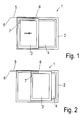
- a sliding door 1 comprises a stationary frame 2, in which a movable sliding leaf 3 is arranged.
- the sliding wing 3 can be moved according to the arrow in the frame 2.
- the sliding leaf 3 has not shown electrical loads, such as a drive for the movement, a drive and a controller for a shading element, a wiring for measuring equipment, ventilation equipment or other components to be supplied with electricity.
- a power cable 5 is provided, which is inserted with one side 6 in the frame 2 and is introduced via a turn loop 8 in the sliding leaf 3, so that a terminal 7 in the sliding panel 3 connected to electrical loads can be.
- the position of the turn loop 8 also changes.
- the power cable 5 is therefore bent and unrolled in the area of the turn loop 8 when the sliding leaf 3 is moved.
- the turn loop 8 is made particularly narrow, so that the friction in the area of the turn loop 8 must be minimized.
- a circular bore is provided in the field of introduction of the power cable 5 in the frame 2 .
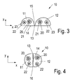
- the power cable 10 includes a molded body having a first part 11 and a second part 12.
- the first part 11 and the second part 12 are formed substantially semicircular in cross-section and connected to one another via a film hinge 13.
- wires 20 and 22 are formed as electrical conductors.
- the core 20 has a larger diameter than the core 22.
- Around the core 20 is disposed an electrically insulating sheath 21, while an electrically insulating sheath 23 is also provided around the core 22 of smaller diameter.
- the power cable 10 is shown in the unfolded position, in which the abutment surfaces 14 on the first part 11 and the second part 12 form a common plane.
- the power cable 10 is formed as a kind of flat cable and can be easily bent about the axis X. This configuration is necessary in the area of the turning cycle 8 when small bending radii are reached should be.
- Adjacent to the film hinge 13, the first part 11 and the second Tel 12 of the molded body via a gap 15 are separated from each other.
- the film hinge 13 is located on the contact surface 14 and forms part of it.
- FIG. 4 the power cable 10 is shown in a folded position.
- the first part 11 and the second part 12 have been pivoted about an axis parallel to the wires 20 and 22 in the region of the film hinge 13, so that the contact surfaces 14 now rest on one another.
- the power cable 10 now has a substantially circular cross section and can be bent both in the X direction and in the Y direction. With this cross-sectional shape, the power cable can be particularly well performed by circular openings or connected to terminals.
- the power cable 10 has in the unfolded position of FIG. 3 a width of about 8 to 10 mm, while the diameter in the folded position of the FIG. 4 is around 4 to 5 mm.
- the film hinge is formed thin and may have a thickness between 0.1 to 0.4 mm, in particular 0.2 mm.
- the molded body with the first part 11, the second part 12 and the film hinge 13 may consist of foamed material, in particular polyurethane, the wires 20 and 22 are preferably made of copper and have an insulating sheath made of soft PVC.
- FIG. 5 the power cable 10 is shown in a possible installation situation in a profile 30 of a window frame 2 or a sash.
- the power cable 10 in the in FIG. 3 Outside this turn loop 8, the power cable 10 in a groove 31 in the folded position of the FIG. 4 be guided so that the power cable 10 is arranged protected.
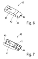
- a guide element 40 which has a housing made of plastic. That in the FIGS. 6 and 7 shown guide member 40 includes an inner channel, in which the Power cable 10 is transferred from the unfolded position to the folded position.
- 40 openings 44 and 45 are formed on opposite sides of the guide element, which have a different cross-section. At the opening 44, the power cable 10 can emerge only in the folded position.
- an opening 45 is provided with a larger cross section, which has a width corresponding to the width of the power cable 10 in the unfolded position.
- the power cable 10 is received in the guide member in the unfolded position, which then passes through a transition region 42 in which the walls of the channel form a contact surface to transfer the power cable 10 from the unfolded to the collapsed position.
- the power cable 10 is held in the folded position.
- FIGS. 8 and 9 is a modified embodiment of a power cable 10 'is shown, which has a shaped body with a first part 11' and a second part 12 ', which are connected to each other via a film hinge 13'.
- the parts 11 'and 12' have a substantially rectangular cross-sectional shape, which is slightly rounded at their edges.
- a larger diameter wire 20 'and a smaller diameter wire 22' are arranged, the wires 20 'and 22' being surrounded by an electrically insulating sheath 21 'and 23', respectively.
- the height is only 2 to 4 mm.
- the film hinge 13 ' is arranged on a lower contact surface 14' of the first part 11 'and the second part 12', so that the parts 11 'and 12' can be pivoted by about 180 ° until the in FIG. 9 shown position is reached. Then, the power cable 10 'has a rectangular or square shape and can be bent in different directions.
- FIGS. 10 and 11 is another embodiment of a power cable 10 "shown, which consists of a molded body made of foamed material having a first part 11" and a second part 12 “, which are connected to each other via a film hinge 13" as in the first embodiment.
- each Part 11 “and 12” has a flat contact surface 14 ", which in the unfolded position of FIG. 10 to develop a common level.
- two cores 20 “and 22" are arranged, which are surrounded by an insulating sheath 21 "or, 23".
- the power cable 10 can be fixed to a strip-shaped projection 51 of a profile 50.
- a thickening 52 in the form of a T-profile is disposed on an outer edge, in the grooves 16" on the first part 11th “and the second part 12” engages.
- the power cable 10 is mechanically fixed to the strip-shaped projection 51, wherein in addition to the contact surfaces 14" of the parts 11 “and 12” adhesive may be provided which glue the power cable 10 "to the projection 51.
- two wires 20 and 22 are provided in the parts 11 and 12, respectively.
- the size, the material and the function of the wires 20 and 22 can be varied, which can be used on the one hand for power supply, but on the other hand also for control.
- holding elements may be provided, for example clamps, molded bodies or other components Fix the power cable 10, 10 ', 10 "in the folded or unfolded position.
Landscapes
- Electric Cable Arrangement Between Relatively Moving Parts (AREA)
- Insulated Conductors (AREA)
Applications Claiming Priority (1)
| Application Number | Priority Date | Filing Date | Title |
|---|---|---|---|
| DE202009009220U DE202009009220U1 (de) | 2009-07-03 | 2009-07-03 | Stromkabel und Stromversorgungseinrichtung |
Publications (2)
| Publication Number | Publication Date |
|---|---|
| EP2270820A2 true EP2270820A2 (fr) | 2011-01-05 |
| EP2270820A3 EP2270820A3 (fr) | 2012-07-25 |
Family
ID=41335379
Family Applications (1)
| Application Number | Title | Priority Date | Filing Date |
|---|---|---|---|
| EP10166310A Withdrawn EP2270820A3 (fr) | 2009-07-03 | 2010-06-17 | Câble électrique et dispositif d'alimentation en courant |
Country Status (2)
| Country | Link |
|---|---|
| EP (1) | EP2270820A3 (fr) |
| DE (1) | DE202009009220U1 (fr) |
Cited By (5)
| Publication number | Priority date | Publication date | Assignee | Title |
|---|---|---|---|---|
| CN103366885A (zh) * | 2013-07-03 | 2013-10-23 | 李竹君 | 一种电线 |
| EP2933418B1 (fr) | 2014-04-18 | 2017-02-15 | PaX AG | Encadrement pour une porte ou une fenêtre avec câblage électrique |
| US20210319931A1 (en) * | 2009-12-09 | 2021-10-14 | Holland Electronics, Llc | Guarded coaxial cable assembly |
| CN113955321A (zh) * | 2021-11-12 | 2022-01-21 | 广东省魔丽显示科技有限公司 | 一种排线角度可稳定调节的结构 |
| US12249440B2 (en) | 2009-12-09 | 2025-03-11 | Holland Electronics, Llc | Guarded coaxial cable assembly |
Family Cites Families (6)
| Publication number | Priority date | Publication date | Assignee | Title |
|---|---|---|---|---|
| GB997508A (en) * | 1963-01-13 | 1965-07-07 | Peter Lombard Johnson | Improvements in and relating to electrical wiring |
| DE9203633U1 (de) * | 1991-08-17 | 1992-05-27 | Elocab Sonderkabel GmbH & Co. KG, 8544 Georgensgmünd | Freitragendes Versorgungskabel |
| FR2709591B1 (fr) * | 1993-09-01 | 1995-10-20 | Merlin Gerin | Câble plat comportant au moins deux conducteurs enrobés dans une gaine isolante. |
| US20050011665A1 (en) * | 2003-07-16 | 2005-01-20 | Youngers Kevin J. | Flexibly-stiffened electrical cable |
| JP4834199B2 (ja) * | 2005-01-17 | 2011-12-14 | 株式会社潤工社 | フラットケーブル |
| US7410387B2 (en) * | 2006-10-04 | 2008-08-12 | 3M Innovative Properties Company | Strain relief for a flat flexible cable |
-
2009
- 2009-07-03 DE DE202009009220U patent/DE202009009220U1/de not_active Expired - Lifetime
-
2010
- 2010-06-17 EP EP10166310A patent/EP2270820A3/fr not_active Withdrawn
Non-Patent Citations (1)
| Title |
|---|
| None |
Cited By (7)
| Publication number | Priority date | Publication date | Assignee | Title |
|---|---|---|---|---|
| US20210319931A1 (en) * | 2009-12-09 | 2021-10-14 | Holland Electronics, Llc | Guarded coaxial cable assembly |
| US11721453B2 (en) * | 2009-12-09 | 2023-08-08 | Holland Electronics, Llc | Guarded coaxial cable assembly |
| US12249440B2 (en) | 2009-12-09 | 2025-03-11 | Holland Electronics, Llc | Guarded coaxial cable assembly |
| CN103366885A (zh) * | 2013-07-03 | 2013-10-23 | 李竹君 | 一种电线 |
| EP2933418B1 (fr) | 2014-04-18 | 2017-02-15 | PaX AG | Encadrement pour une porte ou une fenêtre avec câblage électrique |
| EP2933418B2 (fr) † | 2014-04-18 | 2020-07-15 | PaX AG | Encadrement pour une porte ou une fenêtre avec câblage électrique |
| CN113955321A (zh) * | 2021-11-12 | 2022-01-21 | 广东省魔丽显示科技有限公司 | 一种排线角度可稳定调节的结构 |
Also Published As
| Publication number | Publication date |
|---|---|
| EP2270820A3 (fr) | 2012-07-25 |
| DE202009009220U1 (de) | 2009-11-19 |
Similar Documents
| Publication | Publication Date | Title |
|---|---|---|
| DE2544893C2 (de) | Elektrisches Verbindungselement für eine Klemmverbindung und eine elektrische Verbindung | |
| EP1284033B1 (fr) | Systeme a rail conducteur | |
| EP2419290B1 (fr) | Système de store pour véhicule, module muni d'un système de store pour véhicule et système de toit | |
| DE102019219335A1 (de) | Schienenanordnung | |
| DE69524702T2 (de) | Elektrischer Verbindungskasten | |
| EP2810829B1 (fr) | Clip de fixation | |
| WO2013079221A1 (fr) | Borne de connexion à guidage de conducteur en forme d'élément de liaison | |
| DE112016000327T5 (de) | Schutzelement für elektrische Drähte, mit dem Schutzelement für elektrische Drähte ausgerüsteter Kabelbaum und gleitend bewegliche Verdrahtungsvorrichtung | |
| DE10018680A1 (de) | Kontaktschienenanordnung | |
| DE202012010451U1 (de) | Steckverbinder mit Isolierteil | |
| DE202009009220U1 (de) | Stromkabel und Stromversorgungseinrichtung | |
| DE102007041663A1 (de) | Einrichtung zum Führen von Leitungen, Schläuchen oder dergleichen | |
| EP1162631B1 (fr) | Connecteur pour connecter un câble-ruban plat | |
| EP4678976A2 (fr) | Luminaire avec connecteur détachable | |
| EP2982016B1 (fr) | Fixation modulaire pour conducteur électrique | |
| EP2205793A1 (fr) | Couverture de voie | |
| DE202019105625U1 (de) | Stromabgriffvorrichtung, Anordnung mit einem Stromführungsprofil und einer Stromabgriffvorrichtung | |
| EP2916408A1 (fr) | Agencement et dispositif destinés à former un espace de logement en forme de canal longitudinal | |
| EP3317922B1 (fr) | Coulisse pour la mise en contact électrique de cartes de circuits imprimés | |
| DE102023104652A1 (de) | Berührungsschutzabdeckung, Anschlussteil und Modulverbinder | |
| DE202009013622U1 (de) | Winkelformteil für Kabelkanäle | |
| DE2903867A1 (de) | Schalter fuer lichtleiter | |
| EP3346183B1 (fr) | Système à rail conducteur | |
| EP2044598B1 (fr) | Câble électrique, notamment câble de batterie pour véhicules automobiles | |
| EP1038109B1 (fr) | Appareil electrique a clip de raccordement et logement de clip de raccordement pour le raccordement a un deuxieme appareil electrique |
Legal Events
| Date | Code | Title | Description |
|---|---|---|---|
| PUAI | Public reference made under article 153(3) epc to a published international application that has entered the european phase |
Free format text: ORIGINAL CODE: 0009012 |
|
| AK | Designated contracting states |
Kind code of ref document: A2 Designated state(s): AL AT BE BG CH CY CZ DE DK EE ES FI FR GB GR HR HU IE IS IT LI LT LU LV MC MK MT NL NO PL PT RO SE SI SK SM TR |
|
| AX | Request for extension of the european patent |
Extension state: BA ME RS |
|
| PUAL | Search report despatched |
Free format text: ORIGINAL CODE: 0009013 |
|
| AK | Designated contracting states |
Kind code of ref document: A3 Designated state(s): AL AT BE BG CH CY CZ DE DK EE ES FI FR GB GR HR HU IE IS IT LI LT LU LV MC MK MT NL NO PL PT RO SE SI SK SM TR |
|
| AX | Request for extension of the european patent |
Extension state: BA ME RS |
|
| RIC1 | Information provided on ipc code assigned before grant |
Ipc: H01B 7/40 20060101ALN20120621BHEP Ipc: H02G 11/00 20060101ALI20120621BHEP Ipc: H01B 7/04 20060101AFI20120621BHEP |
|
| STAA | Information on the status of an ep patent application or granted ep patent |
Free format text: STATUS: THE APPLICATION IS DEEMED TO BE WITHDRAWN |
|
| 18D | Application deemed to be withdrawn |
Effective date: 20130126 |