EP2271132A2 - Akustischer Wandler - Google Patents
Akustischer Wandler Download PDFInfo
- Publication number
- EP2271132A2 EP2271132A2 EP10168185A EP10168185A EP2271132A2 EP 2271132 A2 EP2271132 A2 EP 2271132A2 EP 10168185 A EP10168185 A EP 10168185A EP 10168185 A EP10168185 A EP 10168185A EP 2271132 A2 EP2271132 A2 EP 2271132A2
- Authority
- EP
- European Patent Office
- Prior art keywords
- plates
- acoustic radiation
- acoustic
- bending vibration
- acoustic transducer
- Prior art date
- Legal status (The legal status is an assumption and is not a legal conclusion. Google has not performed a legal analysis and makes no representation as to the accuracy of the status listed.)
- Granted
Links
Images





Classifications
-
- B—PERFORMING OPERATIONS; TRANSPORTING
- B06—GENERATING OR TRANSMITTING MECHANICAL VIBRATIONS IN GENERAL
- B06B—METHODS OR APPARATUS FOR GENERATING OR TRANSMITTING MECHANICAL VIBRATIONS OF INFRASONIC, SONIC, OR ULTRASONIC FREQUENCY, e.g. FOR PERFORMING MECHANICAL WORK IN GENERAL
- B06B1/00—Methods or apparatus for generating mechanical vibrations of infrasonic, sonic, or ultrasonic frequency
- B06B1/02—Methods or apparatus for generating mechanical vibrations of infrasonic, sonic, or ultrasonic frequency making use of electrical energy
- B06B1/06—Methods or apparatus for generating mechanical vibrations of infrasonic, sonic, or ultrasonic frequency making use of electrical energy operating with piezoelectric effect or with electrostriction
- B06B1/0607—Methods or apparatus for generating mechanical vibrations of infrasonic, sonic, or ultrasonic frequency making use of electrical energy operating with piezoelectric effect or with electrostriction using multiple elements
-
- H—ELECTRICITY
- H04—ELECTRIC COMMUNICATION TECHNIQUE
- H04R—LOUDSPEAKERS, MICROPHONES, GRAMOPHONE PICK-UPS OR LIKE ACOUSTIC ELECTROMECHANICAL TRANSDUCERS; ELECTRIC HEARING AIDS; PUBLIC ADDRESS SYSTEMS
- H04R17/00—Piezoelectric transducers; Electrostrictive transducers
- H04R17/10—Resonant transducers, i.e. adapted to produce maximum output at a predetermined frequency
-
- H—ELECTRICITY
- H04—ELECTRIC COMMUNICATION TECHNIQUE
- H04R—LOUDSPEAKERS, MICROPHONES, GRAMOPHONE PICK-UPS OR LIKE ACOUSTIC ELECTROMECHANICAL TRANSDUCERS; ELECTRIC HEARING AIDS; PUBLIC ADDRESS SYSTEMS
- H04R7/00—Diaphragms for electromechanical transducers; Cones
- H04R7/02—Diaphragms for electromechanical transducers; Cones characterised by the construction
- H04R7/12—Non-planar diaphragms or cones
-
- H—ELECTRICITY
- H04—ELECTRIC COMMUNICATION TECHNIQUE
- H04R—LOUDSPEAKERS, MICROPHONES, GRAMOPHONE PICK-UPS OR LIKE ACOUSTIC ELECTROMECHANICAL TRANSDUCERS; ELECTRIC HEARING AIDS; PUBLIC ADDRESS SYSTEMS
- H04R1/00—Details of transducers, loudspeakers or microphones
- H04R1/44—Special adaptations for subaqueous use, e.g. for hydrophone
Definitions
- the present invention relates to an acoustic transducer (i.e., electroacoustic converter) which radiates a sound wave into air or water, and in particular to an acoustic transducer capable of efficiently radiating a sound wave at a low frequency.
- an acoustic transducer i.e., electroacoustic converter
- An acoustic transducer which radiates a sound wave into a medium, such as water, is used in the field of oceanographic observation or the like.
- a medium such as water
- an acoustic transducer which radiates a sound wave having a low frequency by excluding many mediums, such as water, in the vicinity of the acoustic radiation surface has come into practical use.
- acoustic transducer of the related art which is used in water
- various types including a bolted Langevin type transducer, a cylindrical transducer, a flextensional transducer, a bending disc-type transducer, a barrel stave-type transducer, and the like are currently used.
- a bolted Langevin transducer (also referred to as a tonpilz transducer due to its shape) 101 shown in FIGS. 14A and 14B is configured such that an acoustic radiation plate 104 is provided on one end surface of a vibrator module 103 having a plurality of annular piezoelectric vibrators 102.
- the vibrator module 103 causes acoustic radiation from the acoustic radiation plate 104 using a vibration mode where the vibrator module 103 longitudinally vibrates in half wavelength.
- a cylindrical transducer 111 shown in FIGS. 15A and 15B is configured such that an acoustic radiation plate 114 is provided on the outer circumferential surface of a cylindrical vibrator 112.
- the cylindrical transducer 111 causes acoustic radiation from the acoustic radiation plate 114 using a breathing vibration mode in a radial direction of the cylindrical vibrator 112, that is, using a mode where longitudinal vibration with one wavelength is formed on the circumferential length of the cylinder.
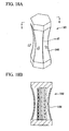
- a flextensional transducer 121 shown in FIGS. 16A and 16B is configured so as to expand the amplitude by converting vibration of a vibrator 122 into bending vibration of a bending acoustic radiation plate 124 using an elliptical shell having an elliptical sectional shape and to cause acoustic radiation of the displacement of the vibrator 122 by using flexural vibration of the bending acoustic radiation plate 124, instead of directly radiating a sound wave into water by using resonance of the vibrator.
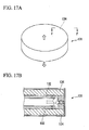
- a bending disc-type transducer 131 shown in FIGS. 17A and 17B is configured such that a disc-type vibrator 132 is bonded to a bending acoustic radiation plate 134, and flexural resonance of the bending acoustic radiation plate 134 is used, thereby causing acoustic radiation of the displacement of the vibrator 132.
- the acoustic transducers 121 and 131 respectively employ the bending acoustic radiation plates 124 and 134 which use bending vibration whose resonance frequency is easily obtained with a low frequency compared to longitudinal vibration, such that many mediums can be excluded.
- a barrel stave-type transducer 141 shown in FIGS. 18A and 18B is configured such that a plurality of bent acoustic radiation plates 144 are provided at the outer circumferential portion, and a gap d1 is provided between adjacent acoustic radiation plates 144.
- an electrodynamic loudspeaker i.e., acoustic transducer which is generally used in air transfers vibration of a coil by an electromagnetic force to a cone paper, thereby causing acoustic radiation from the cone paper.
- acoustic radiation impedance is small, thus it is possible to secure a large excluded medium volume with a lightweight material, such as paper.
- the acoustic transducers of the related art have the following problems.
- the electrodynamic loudspeaker which is used in air
- a larger cone paper is used, and as a result, the loudspeaker increases in size.
- the piezoelectric loudspeaker when the piezoelectric vibrator is bonded to the vibration plate to form acoustic radiation, in order to increase the excluded medium volume, it is necessary to increase the diameter of the vibration plate.
- the specific gravity of the acoustic transducer is close to or smaller than the specific gravity of the medium (such as water). If the specific gravity of the acoustic transducer is greater than that of the medium, a floating buoyant material for floating the acoustic transducer is required, in the case of the underwater sailing body, and the acoustic transducer drops in the case of the towing body where there is no space for providing a floating buoyant material.
- an acoustic transducer which is used in a towing body is accommodated to be cylindrically wound at the time of being accommodated and is substantially used in a linear shape at the time of operation. For this reason, at the time of being accommodated, large bending stress is applied to the acoustic transducer, such that the acoustic transducer is damaged.
- An exemplary object of an embodiment of the invention is to provide an acoustic transducer which can efficiently exclude a medium in the vicinity of an acoustic radiation plate without increasing the shape of a vibrator or acoustic radiation plate.
- an exemplary aspect of the invention provides an acoustic transducer radiates a sound wave into a medium, and includes: a shaft member which extends at a center portion of the acoustic transducer; first and second cylindrical acoustic radiation plates which have a cylindrical shape, a central axis of the first and second cylindrical acoustic radiation plates agreeing with a longitudinal axis of the shaft member, the first and second cylindrical acoustic radiation plates alternately arranged in a direction of the central axis; a plurality of connection members which have a ring shape, and connect adjacent first and second acoustic radiation plates to each other; a plurality of bending vibration plates each of which connects the shaft member and one of the connection members to each other; and a plurality of vibrators which are provided on the bending plates.
- the first acoustic radiation plate has a sectional shape which is curved outwardly in a radial direction thereof, and the sectional shape of the first acoustic radiation plate is along a plane including the central axis.
- the second acoustic radiation plate has a sectional shape which is curved inwardly in a radial direction thereof, and the sectional shape of the second acoustic radiation plate is along a plane including the central axis.
- An exemplary advantage according to the aspect of the invention is that mediums in the vicinity of the first and second acoustic radiation plates can be efficiently excluded without increasing the size of the acoustic radiation plate or the vibrator. Therefore, acoustic radiation with a low frequency can be performed, and a reduction in size and weight of the acoustic transducer can be achieved.
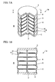
- FIGS. 1A to 5 an acoustic transducer according to a first exemplary embodiment of the invention will be described with reference to FIGS. 1A to 5 .
- an acoustic transducer 1a of the first exemplary embodiment has a shaft (shaft member) 2, end plates 3, first acoustic radiation plates 4, and second acoustic radiation plates 5.
- the shaft 2 extends at the center portion of the acoustic transducer 1a.
- the end plates 3 are provided at both ends of the shaft 2 so that their normal direction agrees with the axial direction of the shaft 2.
- the first acoustic radiation plates 4 have a cylindrical shape such that the sectional shape is curved outwardly at a plane including the axis thereof.
- the second acoustic radiation plates 5 have a cylindrical shape such that the sectional shape is curved inwardly at a plane including the axis thereof.
- the first acoustic radiation plates 4 and the second acoustic radiation plates 5 are alternately arranged between the end plates 3 with their axial directions agreeing with each other.
- a central axis of the first and second acoustic radiation plates 4 and 5 agrees with a longitudinal axis of the shaft 2.
- An acoustic transducer 1a also includes connection members 6 having a ring shape, flexible bending vibration plates 7 having a disc shape and having flexible characteristics, and a piezoelectric vibrator (i.e., vibrator) 8 having a ring shape and having a thin plate shape.
- the ring-shaped connection members 6 are respectively provided between the first acoustic radiation plates 4 and the second acoustic radiation plates 5 to connect the ends of the first acoustic radiation plates 4 and the ends of the second acoustic radiation plates 5.
- the disc-shaped flexible bending vibration plates 7 are respectively fixed inside the connection members 6 so as to be inscribed in the connection members 6.
- the bending vibration plates 7 are fixed to the shaft 2 which passes through the center portions thereof.
- the ring-shaped piezoelectric vibrator 8 is bonded to one surface of each of the bending vibration plates 7.
- the bending vibration plate 7 and the piezoelectric vibrator 8 bonded to one surface of the bending vibration plate 7 constitute a bending vibration module 9 having a unimorph structure.
- the acoustic transducer 1a configured as above is entirely molded with synthetic resin (not shown) or the like and is electrically insulated from an ambient medium M, such as water.
- the first and second acoustic radiation plates 4 and 5 radiate sound waves into a medium such as water, and are formed of a flexible material.
- the first and second acoustic radiation plates 4 and 5 are connected to the bending vibration plates 7 through the connection members 6. Since the bending vibration plates 7 are disc-shaped members which are inscribed in the connection members 6, bending vibration of the bending vibration plates 7 can be transferred to the first and second acoustic radiation plates 4 and 5.
- the first and second acoustic radiation plates 4 and 5 are formed of a synthetic resin or a material containing a synthetic resin, and this material has a honeycomb structure.
- the bending vibration plates 7 are formed of a synthetic resin or a material containing a synthetic resin, and this material has a honeycomb structure or a laminated structure.
- the piezoelectric vibrators 8 are displaced in the up-down direction in accordance with the direction of the application voltage.
- This displacement causes the bending vibration plates 7, to which the piezoelectric vibrators 8 are bonded, to be bent, and the bending vibration plates 7 bending-vibrate in the up-down direction.
- the bending vibration of the bending vibration plates 7 causes the first and second acoustic radiation plates 4 and 5 connected thereto by the connection members 6 to be displaced, such that the ambient medium M is excluded.
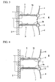
- the connection member 6 is also displaced downward, and a lower end 4b of the first acoustic radiation plate 4 is pulled down.
- curvature the curvature of the sectional shape in the axial direction
- an upper end 5a of the second acoustic radiation plate 5 is compressed from above, thus the curvature increases and the outer circumferential surface thereof is displaced inwardly.
- the respective members before being displaced are represented by dotted lines.
- the ambient medium M can be excluded.
- the first and second acoustic radiation plates 4 and 5 perform inward medium exclusion.
- connection member 6 is also displaced upward, and the lower end 4b of the first acoustic radiation plate 4 is compressed upward, such that the curvature increases and the outer circumferential surface thereof is displaced outwardly. Meanwhile, the upper end 5a of the second acoustic radiation plate 5 is pulled up, thus the curvature is reduced and the outer circumferential surface thereof is displaced outwardly.
- the bending vibration plate 7 is alternately displaced in the up-down direction by the vibration of the piezoelectric vibrator 8, such that the first and second acoustic radiation plates 4 and 5 are alternately displaced inwardly and outwardly to perform medium exclusion.
- the resonance frequency of each of the first and second acoustic radiation plates 4 and 5 is set to be identical to the resonance frequency of each of the bending vibration plates 7.
- Such setting enables superimposition of the displacement of each of the first and second acoustic radiation plates 4 and 5 and the displacement of each of the bending vibration plates 7, thus larger medium exclusion can be performed.
- the displacement directions of adjacent bending vibration plates 7 are identical.
- the upper ends of the first and second acoustic radiation plates 4 and 5 are compressed downward, the lower ends thereof are pulled down.
- the upper ends of the first and second acoustic radiation plates 4 and 5 are compressed downward, the lower ends thereof are pulled down. Therefore, the first and second acoustic radiation plates 4 and 5 are only displaced in the up-down direction, and the curvature of the outer circumferential surface is not changed, and thus, medium exclusion almost never occurs.
- the piezoelectric vibrators 8 are arranged such that the displacement direction of the bending vibration plate 7 is opposite to the displacement direction of the bending vibration plates 7 arranged above and below it.
- the curvature of the outer circumferential surfaces of the first and second acoustic radiation plates 4 and 5 is changed, such that medium exclusion can be efficiently performed.
- a bending vibration plate 7 to which a piezoelectric vibrator 8a having an upward polarization direction is bonded on the upper surface and a bending vibration plate 7 to which a piezoelectric vibrator 8b having a downward polarization direction is bonded on the upper surface are alternately arranged.
- the displacement directions of piezoelectric vibrators 8 adjacent to each other in the up-down direction can be opposite to each other.
- the piezoelectric vibrators 8a and 8b may be respectively arranged on the lower surfaces of the bending vibration plates 7.
- bending vibration plates 7 to which piezoelectric vibrators 8a having an upward polarization direction are bonded on the upper surface are arranged, and the wiring connection to the piezoelectric vibrator 8a arranged on the upper surface of the bending vibration plate and the wiring connection to the piezoelectric vibrator 8a arranged on the lower surface of the bending vibration plate are inverted to each other in the up-down direction. If the bending vibration plates 7 and the piezoelectric vibrators 8a are arranged as described above, the displacement directions of adjacent piezoelectric vibrators 8 in the up-down direction can be opposite to each other.
- a piezoelectric vibrator 8b having a downward polarization direction may be bonded to the upper surface of each of the bending vibration plates 7, or a piezoelectric vibrator 8b having a unified upward or downward polarization direction may be bonded to the lower surface of each of the bending vibration plates 7.
- a bending vibration plate 7 to which a piezoelectric vibrator 8a having an upward polarization direction is bonded on the upper surface and a bending vibration plate 7 to which a piezoelectric vibrator 8b having a downward polarization direction is bonded on the lower surface may be alternately arranged.
- the present embodiment is not limited to the above-described arrangement methods of the bending vibration plates 7 and the piezoelectric vibrators 8.
- the displacement directions of adjacent bending vibration plates 7 may be set to opposite to each other by adjusting at least one of the followings: the positions of the piezoelectric vibrators 8 with respect to the bending vibration plates 7, the polarization directions of the piezoelectric vibrators 8, or the wiring connections to the piezoelectric vibrators 8.
- the acoustic transducer 1a of the first exemplary embodiment is configured such that the cylindrical first acoustic radiation plates 4 having a sectional shape curved outwardly at the plane including the axis in the cylindrical shape and the second acoustic radiation plates 5 having a sectional shape curved inwardly at the plane including the axis in the cylindrical shape are alternately arranged. Further, the first and second acoustic radiation plates 4 and 5 are displaced with the displacement of the bending vibration plates 7, and the curvature of the first and second acoustic radiation plates 4 and 5 is changed.
- the excluded volume of the medium M can be increased, and acoustic radiation with a low frequency can be realized, as compared to an acoustic transducer of the related art which includes a cylindrical acoustic radiation plate whose sectional shape on the plane or in the axial direction is not curved radially.
- the piezoelectric vibrators 8 are arranged such that the displacement directions of adjacent bending vibration plates 7 are opposite to each other, the curvature of the first and second acoustic radiation plates 4 and 5 is changed, resulting in increase in the excluded volume of the medium M.
- the piezoelectric vibrators 8 are bonded to the bending vibration plates 7, such that the bending vibration plates 7 bending-vibrate. Therefore, the resonance frequency can be reduced compared to the longitudinal vibration, and the output frequency can be lowered.
- the sectional shapes along with the axial direction of the first and second acoustic radiation plates 4 and 5 are curved radially, and the curvature of the first and second acoustic radiation plates 4 and 5 is changed with the displacement of the piezoelectric vibrators 8 to perform medium exclusion. Therefore, there is no need to increase the shape of the first and second acoustic radiation plates 4 and 5 or the piezoelectric vibrators 8, and thus reduction in size and weight of the acoustic transducer 1a can be achieved.
- the first and second acoustic radiation plates 4 and 5 are formed of a synthetic resin or a material containing a synthetic resin, and the material has a honeycomb structure. Therefore, the first and second acoustic radiation plates 4 and 5 can be lightweight and have sufficient strength, such that the reduction in weight of the acoustic transducer 1a can be achieved.
- the bending vibration plates 7 are formed of a synthetic resin or a material containing a synthetic resin, and the material has a honeycomb structure or a laminated structure. Therefore, the bending vibration plate 7 can be lightweight and have sufficient strength, such that the reduction in weight of the acoustic transducer 1a can be achieved.
- the end plates 3 are provided at both ends of the shaft 2, such that a medium, such as water, can be prevented from flowing into the first and second acoustic radiation plates 4 and 5.
- an acoustic transducer of a second exemplary embodiment will be described below.
- an acoustic transducer 1b of the second exemplary embodiment is configured such that piezoelectric vibrators 18 are bonded to the upper and lower surfaces of each of the bending vibration plates 17.
- the bending vibration plate 17 and the piezoelectric vibrators 18 bonded to both surfaces of the bending vibration plate 17 constitute a bending vibration module 19 having a bimorph structure.
- the piezoelectric vibrators 18 are arranged such that the displacement direction of each of the bending vibration plates 17 is opposite to the displacement directions of the bending vibration plates 7 arranged above and below the relevant bending vibration plate 7.
- a bending vibration plate 17 to which piezoelectric vibrators 18a having an upward polarization direction are bonded on the upper and lower surface and a bending vibration plate 17 to which piezoelectric vibrators 18b having a downward polarization direction are bonded on the upper and lower surfaces are alternately arranged.
- piezoelectric vibrators 18a and 18b having different polarization directions are arranged on the upper and lower surfaces of the bending vibration plate 17, and the wiring connection to the piezoelectric vibrator 18a and the wiring connection to the piezoelectric vibrator 18b are opposite to each other, such that the displacement directions of adjacent bending vibration plates 17 are opposite to each other.
- the present embodiment is not limited to the above-described arrangement method of the piezoelectric vibrators 18.
- the displacement directions of adjacent bending vibration plates 71 may be set to opposite to each other by adjusting at least one of the followings: the polarization directions of the piezoelectric vibrators 18, or the wiring connections to the piezoelectric vibrators 18 and 19.
- the piezoelectric vibrators 18 are bonded to both surfaces of each of the bending vibration plates 17. Therefore, the bending vibration plates 17 can reliably bending-vibrate compared to the first exemplary embodiment. As a result, medium exclusion by the first and second acoustic radiation plates 14 and 15 can be efficiently performed.
- an acoustic transducer 1c of the third exemplary embodiment is configured such that a plurality of strip-shaped bending vibration plates 27 are arranged radially at predetermined angle intervals around the shaft 22.
- the bending vibration plate 27 is connected to a shaft 22 and a connection member 26.
- a strip-shaped piezoelectric vibrator 28 is bonded to one surface or both surfaces of each of the bending vibration plates 27.
- the bending vibration plate 27 and the piezoelectric vibrator 28 constitute a strip-shaped bending vibration module 29.
- the bending vibration module 9 which is constituted by the disc-shaped bending vibration plate 7 and the ring-shaped piezoelectric vibrator 8 of the first exemplary embodiment shown in FIG. 1A has large rigidity in the circumferential direction, such that the displacement of the bending vibration plates 7 may be disturbed.
- the strip-shaped bending vibration module 29 is provided, such that the rigidity in the radial direction can be reduced compared to the bending vibration module 9 of the first exemplary embodiment, the displacement of the bending vibration plates 27 can be increased, and the excluded medium volume by the acoustic radiation plates 24 and 25 can be increased.
- the volume occupied by the bending vibration plates 27 and piezoelectric vibrators 28 in the bending vibration plates 27 can be reduced compared to the disc-shaped bending radiation plates, thus the reduction in weight of the acoustic transducer 1c can be achieved.
- FIGS. 10A and 10B An acoustic transducer of a fourth exemplary embodiment will be described with reference to FIGS. 10A and 10B .
- drive modules 39 having a plurality of ring-shaped or rectangular piezoelectric vibrators 38 laminated on each other, are each arranged between adjacent bending vibration plates 37.
- the drive modules 39 connect adjacent bending vibration plates 37, and are provided near a shaft 32 of the bending vibration plates 37.
- the drive module 39 has a structure in which the piezoelectric vibrators 38 expand or contract upon application of a voltage. It is set that the expansion and contraction directions of adjacent drive modules 39 are opposite to each other, and the displacement directions of adjacent bending vibration plates 37 are opposite to each other.
- the drive modules 39 are structured such that piezoelectric vibrators 38 having a upward polarization direction and piezoelectric vibrators 38 having a downward polarization direction are alternately laminated on each other.
- the drive modules 39 are structured such that piezoelectric vibrators 38 are laminated on each other with their polarization directions of an upward or downward direction being unified in a laminated direction and the connection lines of the piezoelectric vibrators 38 being inverted. In this way, the piezoelectric vibrators 38 are laminated while adjusting the polarization direction or connection directions such that the expansion and contraction directions of adjacent drive modules 39 differ.
- the bending vibration plates 37 are displaced to approach each other, and the two connection members 36 are close to each other, such that the second acoustic radiation plate 35 between the connection members 36 is displaced inwardly with an increasing flexural curvature and inward medium exclusion is performed. Meanwhile, the first acoustic radiation plates 34 adjacent to this second acoustic radiation plate 35 are extended inwardly and displaced with a decreasing curvature, such that inward medium exclusion is performed.
- the bending vibration plates 37 are displaced to be away from each other, and the two connection members 36 are separated from each other, and the second acoustic radiation plate 35 between the connection members 36 is extended outwardly and displaced with a decreasing curvature, such that outward medium exclusion is performed.
- the first acoustic radiation plates 34 adjacent to this second acoustic radiation plate 35 are bent outwardly and displaced with an increasing curvature, such that outward medium exclusion is performed.
- the drive modules 39 arranged near the shaft 32 of the bending vibration plates 37 connect adjacent bending vibration plates 37, thus bending vibration plates 37 are displaced greatly at the outer edges thereof where the connection members 36 is provided rather than the vicinity of the shaft 32 positioned at the center. Therefore, the displacement of the drive modules 39 can be expanded and transferred to the first and second acoustic radiation plates 34 and 35.
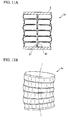
- FIGS. 11A and 11B An acoustic transducer of a fifth exemplary embodiment will be described with reference to FIGS. 11A and 11B .
- hinges 51 are provided in a shaft 42.
- the shaft 42 can be modified to a structure having a curvature, not a straight line, in the axial direction.
- the acoustic transducer 1e can be configured so as to be modified to a structure having a curvature shown in FIG. 11B , not a straight line, in the axial direction.
- the hinges 51 are provided in the shaft 42, such that the acoustic transducer 1e can be modified to a structure having a curvature, not a straight line, in the axial direction. Therefore, bending stress is absorbed when the acoustic transducer is accommodated, such that the acoustic transducer 1e can be prevented from being damaged.
- an acoustic transducer of a sixth exemplary embodiment will be described with reference to FIG. 12 .
- an acoustic transducer If of the sixth exemplary embodiment is configured such that the outer edges of end plates 63 and connection members 66 are greater than the outer edges of first and second acoustic radiation plates 64 and 65. That is, the outer edges of the end plate 63 and the connection members 66 are located outside the outer edges of the first and second acoustic radiation plates 64 and 65 in the radial direction of the first and second acoustic radiation plates 64 and 65.
- the acoustic radiation plate is in contact with the tube because it causes change in the acoustic radiation characteristic.
- the first and second acoustic radiation plates 64 and 65 can be prevented from coming into contact with the tube or the like.
- an acoustic transducer 1g of the seventh exemplary embodiment is configured such that, instead of end plates, bending vibration plates 77 having piezoelectric vibrators 78 provided inward thereof are provided at both ends of a shaft 72.
- the bending vibration plates 77 provided at both ends of the shaft 72 are respectively connected to a first acoustic radiation plate 74 or a second acoustic radiation plate 75.
- the bending vibration plates 77 provided at both ends of the shaft 72 may be respectively connected to the first acoustic radiation plates 74 or the second acoustic radiation plate 75 through connection members (not shown).
- Bending vibration plates 77 which are provided at portions other than both ends of the shaft 72 may have a piezoelectric vibrator on both surfaces, not one surface.
- medium exclusion can be performed by bending vibration of the bending vibration plates 77 provided at both ends of the shaft 72 Accordingly, the excluded medium volume can be increased compared to the first exemplary embodiment.
- the embodiments of invention can be applied to a transmitter which performs acoustic radiation in water.
- the end plates or the bending vibration plates are provided at both ends of the shaft to prevent the ambient medium M from entering the inside of the first and second acoustic radiation plates
- the embodiments may be applied to a water column resonance type acoustic transducer in which the medium M flows therein, without providing end plates or bending vibration plates at both ends of the shaft.
- the first and second acoustic radiation plates or the bending vibration plates are formed of a synthetic resin or a material containing a synthetic resin, and the material has a honeycomb structure or a laminated structure, other materials, such as a metal, may be used.
- a resonance frequency of the first and second acoustic radiation plates is identical to a resonance frequency of the bending vibration plates.
- the first and second acoustic radiation plates are formed of a synthetic resin or a material containing a synthetic resin.
- the first and second acoustic radiation plates are formed of a material having a honeycomb structure.
- the bending vibration plates are formed of a synthetic resin or a material containing a synthetic resin.
- the bending vibration plates are formed of a material having a honeycomb structure or a laminated structure.
- the shaft member has a hinge at an intermediate portion thereof.
- a surface in contact with the medium is molded with a synthetic resin.
Landscapes
- Engineering & Computer Science (AREA)
- Physics & Mathematics (AREA)
- Acoustics & Sound (AREA)
- Signal Processing (AREA)
- Multimedia (AREA)
- Mechanical Engineering (AREA)
- Transducers For Ultrasonic Waves (AREA)
- Piezo-Electric Transducers For Audible Bands (AREA)
Applications Claiming Priority (1)
| Application Number | Priority Date | Filing Date | Title |
|---|---|---|---|
| JP2009158773A JP5257277B2 (ja) | 2009-07-03 | 2009-07-03 | 音響トランスデューサ |
Publications (3)
| Publication Number | Publication Date |
|---|---|
| EP2271132A2 true EP2271132A2 (de) | 2011-01-05 |
| EP2271132A3 EP2271132A3 (de) | 2013-11-06 |
| EP2271132B1 EP2271132B1 (de) | 2014-12-03 |
Family
ID=42830063
Family Applications (1)
| Application Number | Title | Priority Date | Filing Date |
|---|---|---|---|
| EP10168185.6A Active EP2271132B1 (de) | 2009-07-03 | 2010-07-01 | Akustischer Wandler |
Country Status (3)
| Country | Link |
|---|---|
| US (1) | US8265307B2 (de) |
| EP (1) | EP2271132B1 (de) |
| JP (1) | JP5257277B2 (de) |
Cited By (3)
| Publication number | Priority date | Publication date | Assignee | Title |
|---|---|---|---|---|
| CN107950035A (zh) * | 2015-08-07 | 2018-04-20 | 富电电子(株) | 线性声学换能器 |
| CN112530392A (zh) * | 2020-12-04 | 2021-03-19 | 中国船舶重工集团公司第七一五研究所 | 一种多模态宽带大功率指向性发射纵振水声换能器 |
| CN113728659A (zh) * | 2019-04-18 | 2021-11-30 | 弗劳恩霍夫应用研究促进协会 | 微机械声换能器 |
Families Citing this family (15)
| Publication number | Priority date | Publication date | Assignee | Title |
|---|---|---|---|---|
| JP5257277B2 (ja) * | 2009-07-03 | 2013-08-07 | 日本電気株式会社 | 音響トランスデューサ |
| JP5387293B2 (ja) * | 2009-09-29 | 2014-01-15 | 日本電気株式会社 | 音響トランスデューサ |
| JP5445323B2 (ja) * | 2010-05-17 | 2014-03-19 | 日本電気株式会社 | 音響トランスデューサ |
| EP2624595A4 (de) * | 2011-05-19 | 2015-07-01 | Tang Band Ind Co Ltd | Vibrationsplattenvorrichtung für einen elektromagnetischen vibrator und herstellungsverfahren dafür |
| US8670292B2 (en) | 2011-08-12 | 2014-03-11 | Pgs Geophysical As | Electromagnetic linear actuators for marine acoustic vibratory sources |
| US9788122B2 (en) * | 2012-12-26 | 2017-10-10 | Xin Min HUANG | Vibrating panel device for electromagnetic vibrator and manufacture method thereof |
| CN106026769B (zh) * | 2016-06-15 | 2018-09-21 | 浙江师范大学 | 一种自限位伸缩振动式管道发电机 |
| EP3739904B1 (de) * | 2019-05-14 | 2024-10-16 | Fraunhofer-Gesellschaft zur Förderung der angewandten Forschung e.V. | Akustisches biegewandlersystem und akustische vorrichtung |
| CN111263266B (zh) * | 2020-03-03 | 2025-05-02 | 苏州声之源电子科技有限公司 | 双向多级串联弯曲圆盘换能器 |
| CN111212360B (zh) * | 2020-03-03 | 2025-01-21 | 苏州声之源电子科技有限公司 | 双向多级并联弯曲圆盘换能器 |
| WO2021252041A2 (en) * | 2020-03-16 | 2021-12-16 | Tuncdemir Safakcan | Class viii flextensional transducers and method of assembly |
| CN111935594A (zh) * | 2020-07-14 | 2020-11-13 | 中国船舶重工集团公司第七一五研究所 | 一种基于弯曲圆盘换能器的低频宽带高效成阵结构 |
| US12520452B2 (en) | 2022-05-04 | 2026-01-06 | Hoffman Enclosures Inc. | Replaceable pump unit for cooling systems |
| US20240107227A1 (en) * | 2022-09-25 | 2024-03-28 | Clark Synthesis, Inc. | Underwater surface mountable speaker |
| KR102915200B1 (ko) * | 2023-11-27 | 2026-01-20 | 국방과학연구소 | 다중공진 플렉스텐셔널 저주파 음향 프로젝터 |
Citations (2)
| Publication number | Priority date | Publication date | Assignee | Title |
|---|---|---|---|---|
| US4922470A (en) | 1988-11-15 | 1990-05-01 | Her Majesty The Queen In Right Of Canada, As Represented By The Minister Of National Defence Of Her Majesty's Canadian Government | Barrel stave projector |
| JPH05344582A (ja) | 1992-06-08 | 1993-12-24 | Nec Corp | 低周波水中送波器 |
Family Cites Families (19)
| Publication number | Priority date | Publication date | Assignee | Title |
|---|---|---|---|---|
| US4056742A (en) * | 1976-04-30 | 1977-11-01 | Tibbetts Industries, Inc. | Transducer having piezoelectric film arranged with alternating curvatures |
| JP2581466B2 (ja) * | 1994-09-28 | 1997-02-12 | 日本電気株式会社 | 低周波水中送波器 |
| NO301796B1 (no) * | 1995-05-18 | 1997-12-08 | Unaco Systems Ab | Drivenhet for akustiske sendere |
| WO1998035529A2 (en) * | 1997-02-07 | 1998-08-13 | Sri International | Elastomeric dielectric polymer film sonic actuator |
| US5805529A (en) * | 1997-09-17 | 1998-09-08 | Her Majesty The Queen In Right Of Canada, As Represented By The Minister Of National Defence Of Her Majesty's Canadian Government | Folded shell projector (FSP) |
| US20050100181A1 (en) * | 1998-09-24 | 2005-05-12 | Particle Measuring Systems, Inc. | Parametric transducer having an emitter film |
| US7166098B1 (en) * | 1999-12-30 | 2007-01-23 | Advanced Cardiovascular Systems, Inc. | Medical assembly with transducer for local delivery of a therapeutic substance and method of using same |
| CA2396260C (en) * | 2000-01-07 | 2007-09-11 | Lewis Athanas | Mechanical-to-acoustical transformer and multi-media flat film speaker |
| JP3520837B2 (ja) * | 2000-05-22 | 2004-04-19 | 日本電気株式会社 | 屈曲型送受波器 |
| CA2374299A1 (en) * | 2002-03-01 | 2003-09-01 | Charles Whitman Fox | Modular microphone array for surround sound recording |
| US7081699B2 (en) * | 2003-03-31 | 2006-07-25 | The Penn State Research Foundation | Thermoacoustic piezoelectric generator |
| US7181038B2 (en) * | 2004-03-10 | 2007-02-20 | Ksc Industries Incorporated | Electro-acoustic transducer |
| US7466066B2 (en) * | 2004-11-05 | 2008-12-16 | Lockheed Martin Corporation | Longitudinally driven slotted cylinder transducer |
| JP4946272B2 (ja) * | 2006-08-30 | 2012-06-06 | 日本電気株式会社 | 電気音響変換器および該電気音響変換器を搭載するソーナー用送信器 |
| US7677673B2 (en) * | 2006-09-26 | 2010-03-16 | Hw Advanced Technologies, Inc. | Stimulation and recovery of heavy hydrocarbon fluids |
| JP5257277B2 (ja) * | 2009-07-03 | 2013-08-07 | 日本電気株式会社 | 音響トランスデューサ |
| JP5304492B2 (ja) * | 2009-07-03 | 2013-10-02 | 日本電気株式会社 | 音響トランスデューサ |
| JP5387293B2 (ja) * | 2009-09-29 | 2014-01-15 | 日本電気株式会社 | 音響トランスデューサ |
| JP5445323B2 (ja) * | 2010-05-17 | 2014-03-19 | 日本電気株式会社 | 音響トランスデューサ |
-
2009
- 2009-07-03 JP JP2009158773A patent/JP5257277B2/ja active Active
-
2010
- 2010-07-01 US US12/829,142 patent/US8265307B2/en active Active
- 2010-07-01 EP EP10168185.6A patent/EP2271132B1/de active Active
Patent Citations (2)
| Publication number | Priority date | Publication date | Assignee | Title |
|---|---|---|---|---|
| US4922470A (en) | 1988-11-15 | 1990-05-01 | Her Majesty The Queen In Right Of Canada, As Represented By The Minister Of National Defence Of Her Majesty's Canadian Government | Barrel stave projector |
| JPH05344582A (ja) | 1992-06-08 | 1993-12-24 | Nec Corp | 低周波水中送波器 |
Cited By (4)
| Publication number | Priority date | Publication date | Assignee | Title |
|---|---|---|---|---|
| CN107950035A (zh) * | 2015-08-07 | 2018-04-20 | 富电电子(株) | 线性声学换能器 |
| CN113728659A (zh) * | 2019-04-18 | 2021-11-30 | 弗劳恩霍夫应用研究促进协会 | 微机械声换能器 |
| CN113728659B (zh) * | 2019-04-18 | 2023-08-18 | 弗劳恩霍夫应用研究促进协会 | 微机械声换能器 |
| CN112530392A (zh) * | 2020-12-04 | 2021-03-19 | 中国船舶重工集团公司第七一五研究所 | 一种多模态宽带大功率指向性发射纵振水声换能器 |
Also Published As
| Publication number | Publication date |
|---|---|
| JP5257277B2 (ja) | 2013-08-07 |
| US20110002484A1 (en) | 2011-01-06 |
| JP2011015270A (ja) | 2011-01-20 |
| EP2271132A3 (de) | 2013-11-06 |
| US8265307B2 (en) | 2012-09-11 |
| EP2271132B1 (de) | 2014-12-03 |
Similar Documents
| Publication | Publication Date | Title |
|---|---|---|
| US8265307B2 (en) | Acoustic transducer | |
| JP5387293B2 (ja) | 音響トランスデューサ | |
| CN103841499A (zh) | 一种施加预应力的叠堆压电圆管换能器 | |
| JP5445323B2 (ja) | 音響トランスデューサ | |
| CN100561575C (zh) | 碟型发射换能器 | |
| JP5304492B2 (ja) | 音響トランスデューサ | |
| US20230146098A1 (en) | Class VIII Flextensional Transducers and Method of Assembly | |
| JP2008244895A (ja) | 屈曲型送受波器 | |
| US4462093A (en) | Symmetrical shell support for flextensional transducer | |
| US8786164B2 (en) | Acoustic transducer | |
| JP2985509B2 (ja) | 低周波水中送波器 | |
| JP2671855B2 (ja) | 水中音響送波器 | |
| JP2006005403A (ja) | 超音波送受波器 | |
| JP5309941B2 (ja) | 音響トランスデューサ | |
| JPS6143898A (ja) | 電気音響変換器 | |
| JP4765782B2 (ja) | 水中送波器及び水中送波方法 | |
| KR102915200B1 (ko) | 다중공진 플렉스텐셔널 저주파 음향 프로젝터 | |
| KR100517061B1 (ko) | 수중 음향 트랜스듀서 | |
| JP2581466B2 (ja) | 低周波水中送波器 | |
| JP2024070453A (ja) | 送受波装置および送受波方法 | |
| RU2228578C1 (ru) | Электроакустический преобразователь | |
| CN121751050A (zh) | 一种多开缝式圆环水声换能器 | |
| JPH0759196A (ja) | 電気音響変換器 | |
| JP4640033B2 (ja) | 屈曲型送波器およびそのシェル | |
| JP2910412B2 (ja) | 低周波水中超音波送波器 |
Legal Events
| Date | Code | Title | Description |
|---|---|---|---|
| PUAI | Public reference made under article 153(3) epc to a published international application that has entered the european phase |
Free format text: ORIGINAL CODE: 0009012 |
|
| AK | Designated contracting states |
Kind code of ref document: A2 Designated state(s): AL AT BE BG CH CY CZ DE DK EE ES FI FR GB GR HR HU IE IS IT LI LT LU LV MC MK MT NL NO PL PT RO SE SI SK SM TR |
|
| AX | Request for extension of the european patent |
Extension state: BA ME RS |
|
| PUAL | Search report despatched |
Free format text: ORIGINAL CODE: 0009013 |
|
| AK | Designated contracting states |
Kind code of ref document: A3 Designated state(s): AL AT BE BG CH CY CZ DE DK EE ES FI FR GB GR HR HU IE IS IT LI LT LU LV MC MK MT NL NO PL PT RO SE SI SK SM TR |
|
| AX | Request for extension of the european patent |
Extension state: BA ME RS |
|
| RIC1 | Information provided on ipc code assigned before grant |
Ipc: G10K 9/12 20060101ALI20130927BHEP Ipc: H04R 7/12 20060101ALI20130927BHEP Ipc: H04R 17/10 20060101ALI20130927BHEP Ipc: H04R 17/00 20060101AFI20130927BHEP Ipc: H04R 1/44 20060101ALI20130927BHEP |
|
| 17P | Request for examination filed |
Effective date: 20140506 |
|
| RBV | Designated contracting states (corrected) |
Designated state(s): AL AT BE BG CH CY CZ DE DK EE ES FI FR GB GR HR HU IE IS IT LI LT LU LV MC MK MT NL NO PL PT RO SE SI SK SM TR |
|
| GRAP | Despatch of communication of intention to grant a patent |
Free format text: ORIGINAL CODE: EPIDOSNIGR1 |
|
| RIC1 | Information provided on ipc code assigned before grant |
Ipc: H04R 17/10 20060101ALI20140606BHEP Ipc: G10K 9/12 20060101ALI20140606BHEP Ipc: H04R 17/00 20060101AFI20140606BHEP Ipc: H04R 7/12 20060101ALI20140606BHEP Ipc: H04R 1/44 20060101ALI20140606BHEP |
|
| INTG | Intention to grant announced |
Effective date: 20140630 |
|
| GRAS | Grant fee paid |
Free format text: ORIGINAL CODE: EPIDOSNIGR3 |
|
| GRAA | (expected) grant |
Free format text: ORIGINAL CODE: 0009210 |
|
| AK | Designated contracting states |
Kind code of ref document: B1 Designated state(s): AL AT BE BG CH CY CZ DE DK EE ES FI FR GB GR HR HU IE IS IT LI LT LU LV MC MK MT NL NO PL PT RO SE SI SK SM TR |
|
| REG | Reference to a national code |
Ref country code: GB Ref legal event code: FG4D |
|
| REG | Reference to a national code |
Ref country code: AT Ref legal event code: REF Ref document number: 699980 Country of ref document: AT Kind code of ref document: T Effective date: 20141215 Ref country code: CH Ref legal event code: EP |
|
| REG | Reference to a national code |
Ref country code: IE Ref legal event code: FG4D |
|
| REG | Reference to a national code |
Ref country code: DE Ref legal event code: R096 Ref document number: 602010020652 Country of ref document: DE Effective date: 20150115 |
|
| REG | Reference to a national code |
Ref country code: NL Ref legal event code: VDEP Effective date: 20141203 |
|
| REG | Reference to a national code |
Ref country code: AT Ref legal event code: MK05 Ref document number: 699980 Country of ref document: AT Kind code of ref document: T Effective date: 20141203 |
|
| PG25 | Lapsed in a contracting state [announced via postgrant information from national office to epo] |
Ref country code: LT Free format text: LAPSE BECAUSE OF FAILURE TO SUBMIT A TRANSLATION OF THE DESCRIPTION OR TO PAY THE FEE WITHIN THE PRESCRIBED TIME-LIMIT Effective date: 20141203 Ref country code: ES Free format text: LAPSE BECAUSE OF FAILURE TO SUBMIT A TRANSLATION OF THE DESCRIPTION OR TO PAY THE FEE WITHIN THE PRESCRIBED TIME-LIMIT Effective date: 20141203 Ref country code: NL Free format text: LAPSE BECAUSE OF FAILURE TO SUBMIT A TRANSLATION OF THE DESCRIPTION OR TO PAY THE FEE WITHIN THE PRESCRIBED TIME-LIMIT Effective date: 20141203 Ref country code: FI Free format text: LAPSE BECAUSE OF FAILURE TO SUBMIT A TRANSLATION OF THE DESCRIPTION OR TO PAY THE FEE WITHIN THE PRESCRIBED TIME-LIMIT Effective date: 20141203 Ref country code: NO Free format text: LAPSE BECAUSE OF FAILURE TO SUBMIT A TRANSLATION OF THE DESCRIPTION OR TO PAY THE FEE WITHIN THE PRESCRIBED TIME-LIMIT Effective date: 20150303 |
|
| REG | Reference to a national code |
Ref country code: LT Ref legal event code: MG4D |
|
| PG25 | Lapsed in a contracting state [announced via postgrant information from national office to epo] |
Ref country code: HR Free format text: LAPSE BECAUSE OF FAILURE TO SUBMIT A TRANSLATION OF THE DESCRIPTION OR TO PAY THE FEE WITHIN THE PRESCRIBED TIME-LIMIT Effective date: 20141203 Ref country code: AT Free format text: LAPSE BECAUSE OF FAILURE TO SUBMIT A TRANSLATION OF THE DESCRIPTION OR TO PAY THE FEE WITHIN THE PRESCRIBED TIME-LIMIT Effective date: 20141203 Ref country code: LV Free format text: LAPSE BECAUSE OF FAILURE TO SUBMIT A TRANSLATION OF THE DESCRIPTION OR TO PAY THE FEE WITHIN THE PRESCRIBED TIME-LIMIT Effective date: 20141203 Ref country code: SE Free format text: LAPSE BECAUSE OF FAILURE TO SUBMIT A TRANSLATION OF THE DESCRIPTION OR TO PAY THE FEE WITHIN THE PRESCRIBED TIME-LIMIT Effective date: 20141203 Ref country code: GR Free format text: LAPSE BECAUSE OF FAILURE TO SUBMIT A TRANSLATION OF THE DESCRIPTION OR TO PAY THE FEE WITHIN THE PRESCRIBED TIME-LIMIT Effective date: 20150304 Ref country code: CY Free format text: LAPSE BECAUSE OF FAILURE TO SUBMIT A TRANSLATION OF THE DESCRIPTION OR TO PAY THE FEE WITHIN THE PRESCRIBED TIME-LIMIT Effective date: 20141203 |
|
| PG25 | Lapsed in a contracting state [announced via postgrant information from national office to epo] |
Ref country code: RO Free format text: LAPSE BECAUSE OF FAILURE TO SUBMIT A TRANSLATION OF THE DESCRIPTION OR TO PAY THE FEE WITHIN THE PRESCRIBED TIME-LIMIT Effective date: 20141203 Ref country code: EE Free format text: LAPSE BECAUSE OF FAILURE TO SUBMIT A TRANSLATION OF THE DESCRIPTION OR TO PAY THE FEE WITHIN THE PRESCRIBED TIME-LIMIT Effective date: 20141203 Ref country code: SK Free format text: LAPSE BECAUSE OF FAILURE TO SUBMIT A TRANSLATION OF THE DESCRIPTION OR TO PAY THE FEE WITHIN THE PRESCRIBED TIME-LIMIT Effective date: 20141203 Ref country code: CZ Free format text: LAPSE BECAUSE OF FAILURE TO SUBMIT A TRANSLATION OF THE DESCRIPTION OR TO PAY THE FEE WITHIN THE PRESCRIBED TIME-LIMIT Effective date: 20141203 Ref country code: PT Free format text: LAPSE BECAUSE OF FAILURE TO SUBMIT A TRANSLATION OF THE DESCRIPTION OR TO PAY THE FEE WITHIN THE PRESCRIBED TIME-LIMIT Effective date: 20150403 |
|
| PG25 | Lapsed in a contracting state [announced via postgrant information from national office to epo] |
Ref country code: IS Free format text: LAPSE BECAUSE OF FAILURE TO SUBMIT A TRANSLATION OF THE DESCRIPTION OR TO PAY THE FEE WITHIN THE PRESCRIBED TIME-LIMIT Effective date: 20150403 Ref country code: PL Free format text: LAPSE BECAUSE OF FAILURE TO SUBMIT A TRANSLATION OF THE DESCRIPTION OR TO PAY THE FEE WITHIN THE PRESCRIBED TIME-LIMIT Effective date: 20141203 |
|
| REG | Reference to a national code |
Ref country code: DE Ref legal event code: R097 Ref document number: 602010020652 Country of ref document: DE |
|
| PLBE | No opposition filed within time limit |
Free format text: ORIGINAL CODE: 0009261 |
|
| STAA | Information on the status of an ep patent application or granted ep patent |
Free format text: STATUS: NO OPPOSITION FILED WITHIN TIME LIMIT |
|
| PG25 | Lapsed in a contracting state [announced via postgrant information from national office to epo] |
Ref country code: DK Free format text: LAPSE BECAUSE OF FAILURE TO SUBMIT A TRANSLATION OF THE DESCRIPTION OR TO PAY THE FEE WITHIN THE PRESCRIBED TIME-LIMIT Effective date: 20141203 |
|
| 26N | No opposition filed |
Effective date: 20150904 |
|
| PG25 | Lapsed in a contracting state [announced via postgrant information from national office to epo] |
Ref country code: IT Free format text: LAPSE BECAUSE OF FAILURE TO SUBMIT A TRANSLATION OF THE DESCRIPTION OR TO PAY THE FEE WITHIN THE PRESCRIBED TIME-LIMIT Effective date: 20141203 |
|
| PG25 | Lapsed in a contracting state [announced via postgrant information from national office to epo] |
Ref country code: SI Free format text: LAPSE BECAUSE OF FAILURE TO SUBMIT A TRANSLATION OF THE DESCRIPTION OR TO PAY THE FEE WITHIN THE PRESCRIBED TIME-LIMIT Effective date: 20141203 Ref country code: MC Free format text: LAPSE BECAUSE OF FAILURE TO SUBMIT A TRANSLATION OF THE DESCRIPTION OR TO PAY THE FEE WITHIN THE PRESCRIBED TIME-LIMIT Effective date: 20141203 |
|
| REG | Reference to a national code |
Ref country code: CH Ref legal event code: PL |
|
| PG25 | Lapsed in a contracting state [announced via postgrant information from national office to epo] |
Ref country code: LU Free format text: LAPSE BECAUSE OF FAILURE TO SUBMIT A TRANSLATION OF THE DESCRIPTION OR TO PAY THE FEE WITHIN THE PRESCRIBED TIME-LIMIT Effective date: 20150701 |
|
| REG | Reference to a national code |
Ref country code: IE Ref legal event code: MM4A |
|
| PG25 | Lapsed in a contracting state [announced via postgrant information from national office to epo] |
Ref country code: LI Free format text: LAPSE BECAUSE OF NON-PAYMENT OF DUE FEES Effective date: 20150731 Ref country code: CH Free format text: LAPSE BECAUSE OF NON-PAYMENT OF DUE FEES Effective date: 20150731 |
|
| PG25 | Lapsed in a contracting state [announced via postgrant information from national office to epo] |
Ref country code: BE Free format text: LAPSE BECAUSE OF FAILURE TO SUBMIT A TRANSLATION OF THE DESCRIPTION OR TO PAY THE FEE WITHIN THE PRESCRIBED TIME-LIMIT Effective date: 20141203 |
|
| REG | Reference to a national code |
Ref country code: FR Ref legal event code: PLFP Year of fee payment: 7 |
|
| PG25 | Lapsed in a contracting state [announced via postgrant information from national office to epo] |
Ref country code: IE Free format text: LAPSE BECAUSE OF NON-PAYMENT OF DUE FEES Effective date: 20150701 |
|
| PG25 | Lapsed in a contracting state [announced via postgrant information from national office to epo] |
Ref country code: MT Free format text: LAPSE BECAUSE OF FAILURE TO SUBMIT A TRANSLATION OF THE DESCRIPTION OR TO PAY THE FEE WITHIN THE PRESCRIBED TIME-LIMIT Effective date: 20141203 |
|
| PG25 | Lapsed in a contracting state [announced via postgrant information from national office to epo] |
Ref country code: HU Free format text: LAPSE BECAUSE OF FAILURE TO SUBMIT A TRANSLATION OF THE DESCRIPTION OR TO PAY THE FEE WITHIN THE PRESCRIBED TIME-LIMIT; INVALID AB INITIO Effective date: 20100701 Ref country code: BG Free format text: LAPSE BECAUSE OF FAILURE TO SUBMIT A TRANSLATION OF THE DESCRIPTION OR TO PAY THE FEE WITHIN THE PRESCRIBED TIME-LIMIT Effective date: 20141203 Ref country code: SM Free format text: LAPSE BECAUSE OF FAILURE TO SUBMIT A TRANSLATION OF THE DESCRIPTION OR TO PAY THE FEE WITHIN THE PRESCRIBED TIME-LIMIT Effective date: 20141203 |
|
| REG | Reference to a national code |
Ref country code: FR Ref legal event code: PLFP Year of fee payment: 8 |
|
| PG25 | Lapsed in a contracting state [announced via postgrant information from national office to epo] |
Ref country code: TR Free format text: LAPSE BECAUSE OF FAILURE TO SUBMIT A TRANSLATION OF THE DESCRIPTION OR TO PAY THE FEE WITHIN THE PRESCRIBED TIME-LIMIT Effective date: 20141203 |
|
| REG | Reference to a national code |
Ref country code: FR Ref legal event code: PLFP Year of fee payment: 9 |
|
| PG25 | Lapsed in a contracting state [announced via postgrant information from national office to epo] |
Ref country code: MK Free format text: LAPSE BECAUSE OF FAILURE TO SUBMIT A TRANSLATION OF THE DESCRIPTION OR TO PAY THE FEE WITHIN THE PRESCRIBED TIME-LIMIT Effective date: 20141203 |
|
| PG25 | Lapsed in a contracting state [announced via postgrant information from national office to epo] |
Ref country code: AL Free format text: LAPSE BECAUSE OF FAILURE TO SUBMIT A TRANSLATION OF THE DESCRIPTION OR TO PAY THE FEE WITHIN THE PRESCRIBED TIME-LIMIT Effective date: 20141203 |
|
| PGFP | Annual fee paid to national office [announced via postgrant information from national office to epo] |
Ref country code: DE Payment date: 20250722 Year of fee payment: 16 |
|
| PGFP | Annual fee paid to national office [announced via postgrant information from national office to epo] |
Ref country code: GB Payment date: 20250722 Year of fee payment: 16 |
|
| PGFP | Annual fee paid to national office [announced via postgrant information from national office to epo] |
Ref country code: FR Payment date: 20250725 Year of fee payment: 16 |