EP2271830B1 - Carénage pour un moteur à turbine à gaz - Google Patents
Carénage pour un moteur à turbine à gaz Download PDFInfo
- Publication number
- EP2271830B1 EP2271830B1 EP09752535.6A EP09752535A EP2271830B1 EP 2271830 B1 EP2271830 B1 EP 2271830B1 EP 09752535 A EP09752535 A EP 09752535A EP 2271830 B1 EP2271830 B1 EP 2271830B1
- Authority
- EP
- European Patent Office
- Prior art keywords
- fairing
- locating component
- strut
- sheath
- assembly
- Prior art date
- Legal status (The legal status is an assumption and is not a legal conclusion. Google has not performed a legal analysis and makes no representation as to the accuracy of the status listed.)
- Active
Links
Images

Classifications
-
- F—MECHANICAL ENGINEERING; LIGHTING; HEATING; WEAPONS; BLASTING
- F01—MACHINES OR ENGINES IN GENERAL; ENGINE PLANTS IN GENERAL; STEAM ENGINES
- F01D—NON-POSITIVE DISPLACEMENT MACHINES OR ENGINES, e.g. STEAM TURBINES
- F01D25/00—Component parts, details, or accessories, not provided for in, or of interest apart from, other groups
- F01D25/28—Supporting or mounting arrangements, e.g. for turbine casing
-
- F—MECHANICAL ENGINEERING; LIGHTING; HEATING; WEAPONS; BLASTING
- F01—MACHINES OR ENGINES IN GENERAL; ENGINE PLANTS IN GENERAL; STEAM ENGINES
- F01D—NON-POSITIVE DISPLACEMENT MACHINES OR ENGINES, e.g. STEAM TURBINES
- F01D9/00—Stators
- F01D9/02—Nozzles; Nozzle boxes; Stator blades; Guide conduits, e.g. individual nozzles
- F01D9/04—Nozzles; Nozzle boxes; Stator blades; Guide conduits, e.g. individual nozzles forming ring or sector
- F01D9/041—Nozzles; Nozzle boxes; Stator blades; Guide conduits, e.g. individual nozzles forming ring or sector using blades
-
- F—MECHANICAL ENGINEERING; LIGHTING; HEATING; WEAPONS; BLASTING
- F02—COMBUSTION ENGINES; HOT-GAS OR COMBUSTION-PRODUCT ENGINE PLANTS
- F02C—GAS-TURBINE PLANTS; AIR INTAKES FOR JET-PROPULSION PLANTS; CONTROLLING FUEL SUPPLY IN AIR-BREATHING JET-PROPULSION PLANTS
- F02C7/00—Features, components parts, details or accessories, not provided for in, or of interest apart form groups F02C1/00 - F02C6/00; Air intakes for jet-propulsion plants
- F02C7/20—Mounting or supporting of plant; Accommodating heat expansion or creep
-
- F—MECHANICAL ENGINEERING; LIGHTING; HEATING; WEAPONS; BLASTING
- F05—INDEXING SCHEMES RELATING TO ENGINES OR PUMPS IN VARIOUS SUBCLASSES OF CLASSES F01-F04
- F05D—INDEXING SCHEME FOR ASPECTS RELATING TO NON-POSITIVE-DISPLACEMENT MACHINES OR ENGINES, GAS-TURBINES OR JET-PROPULSION PLANTS
- F05D2240/00—Components
- F05D2240/10—Stators
- F05D2240/12—Fluid guiding means, e.g. vanes
-
- F—MECHANICAL ENGINEERING; LIGHTING; HEATING; WEAPONS; BLASTING
- F05—INDEXING SCHEMES RELATING TO ENGINES OR PUMPS IN VARIOUS SUBCLASSES OF CLASSES F01-F04
- F05D—INDEXING SCHEME FOR ASPECTS RELATING TO NON-POSITIVE-DISPLACEMENT MACHINES OR ENGINES, GAS-TURBINES OR JET-PROPULSION PLANTS
- F05D2240/00—Components
- F05D2240/10—Stators
- F05D2240/12—Fluid guiding means, e.g. vanes
- F05D2240/121—Fluid guiding means, e.g. vanes related to the leading edge of a stator vane
-
- F—MECHANICAL ENGINEERING; LIGHTING; HEATING; WEAPONS; BLASTING
- F05—INDEXING SCHEMES RELATING TO ENGINES OR PUMPS IN VARIOUS SUBCLASSES OF CLASSES F01-F04
- F05D—INDEXING SCHEME FOR ASPECTS RELATING TO NON-POSITIVE-DISPLACEMENT MACHINES OR ENGINES, GAS-TURBINES OR JET-PROPULSION PLANTS
- F05D2240/00—Components
- F05D2240/20—Rotors
- F05D2240/30—Characteristics of rotor blades, i.e. of any element transforming dynamic fluid energy to or from rotational energy and being attached to a rotor
- F05D2240/303—Characteristics of rotor blades, i.e. of any element transforming dynamic fluid energy to or from rotational energy and being attached to a rotor related to the leading edge of a rotor blade
-
- F—MECHANICAL ENGINEERING; LIGHTING; HEATING; WEAPONS; BLASTING
- F05—INDEXING SCHEMES RELATING TO ENGINES OR PUMPS IN VARIOUS SUBCLASSES OF CLASSES F01-F04
- F05D—INDEXING SCHEME FOR ASPECTS RELATING TO NON-POSITIVE-DISPLACEMENT MACHINES OR ENGINES, GAS-TURBINES OR JET-PROPULSION PLANTS
- F05D2260/00—Function
- F05D2260/30—Retaining components in desired mutual position
- F05D2260/36—Retaining components in desired mutual position by a form fit connection, e.g. by interlocking
Definitions
- the disclosure generally relates to gas turbine engines.
- a gas turbine engine typically includes an annular gas path that generally extends between an inlet and an exhaust.
- the structure used to define the gas path is oftentimes supported by struts and/or fairings that extend across the gas path, with corresponding ends of the struts and/or fairings typically supporting one or more rotating shafts of the engine and the opposing ends supporting the engine casing.
- a fairing assembly having the features of the preamble of claim 1 is disclosed in US2006/269405 A1 .
- Other fairing assemblies are disclosed in BE-673345 , GB-A-2210415 and US-A-4993918 .
- locating components are provided that establish desired spacing between fairing sheaths and the struts that extend through the sheaths.
- the locating components are positioned in a vicinity of the leading edges of the struts and can be used to form a crumple zone for protecting downstream struts.
- one or more locating components can be used in a fairing to create a hollow cavity between the fairing sheath and a strut.
- FIG. 1 depicts an exemplary embodiment of a gas turbine engine.
- engine 100 is depicted as a turbojet that incorporates a compressor section 102, a combustion section 104 and a turbine section 106.
- a fairing assembly 110 is positioned upstream of the compressor section.
- turbojet gas turbine engine it should be understood that the concepts described herein are not limited to use with turbojets as the teachings may be applied to other types of gas turbine engines.
- Fairing assembly 110 includes multiple fairings (e.g., fairing 112) that extend about an axis 114.
- fairing 112 includes a fairing sheath 116, a locating component 118 and a strut 120.
- locating component 118 extends along a length of the fairing.
- locating component 118 is positioned between fairing sheath 116 and strut 120. Specifically, the locating component is positioned in a channel 130 formed by the interior surface 132 of the fairing sheath in a vicinity of the leading edge 134 of the fairing sheath.
- Locating component 118 is generally wedge-shaped in cross-sectional view, and incorporates a leading edge 142, sides 144, 146 extending from the leading edge, and an aft portion 148.
- Datum surfaces 150, 152 and 154 define a recess 156 positioned along the aft portion.
- a leading edge portion 159 of strut 120 contacts datum surface 150 to establish a desired orientation of the strut and fairing sheath.
- contact between the strut and the locating component sets a desired axial spacing between the interior surface 132 of the fairing sheath and the strut, particularly in a vicinity of leading edge 134.
- the sides 144, 146 of the locating component function as guides for the fairing sheath as the sheath extends aft from the leading edge and about at least a portion of the strut.
- the fairing sheath can be adhered to the locating component.
- Locating component 160 is generally wedge-shaped although various other shapes can be used in other embodiments.
- Locating component 160 includes a leading edge 162, sides 164, 165 extending from the leading edge, opposing ends 166, 167, and an aft portion 168.
- Aft portion 168 includes a generally planar datum surface 169 that interconnects the sides and ends of the locating component.
- the datum surface 169 is used as a reference surface for positioning a fairing sheath in a desired orientation about one or more struts that are to be positioned within the cavity formed by the fairing sheath.
- locating component 160 is formed of thermal plastic material, although various other materials can be used in other embodiments. Selection of the one or more materials used to form the locating component can be based on one or more of various factors, such as durability, bondability and heat resistance, for example. In some embodiments, a thermal plastic such as polyamide-imide can be used.
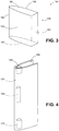
- FIG. 4 is a schematic diagram depicting another exemplary embodiment of a fairing.
- this embodiment includes multiple locating components.
- fairing 180 includes a fairing sheath 182 and locating components 170, 186 and 188.
- the locating components in addition to assisting in orienting the fairing sheath relative to a strut (not shown), are spaced from each other to form cavities within channel 190.
- the cavities e.g., cavity 192 can be used for routing various components, such as wiring and fluid conduits, for example.
- the locating components exhibit differences in size and shape. For instance, component 188 is relatively long and narrow, whereas component 186 is relatively short and wide.
- selection of the materials, sizes and/or shapes of the locating components as well as the positions of the location components can be used to alter characteristics, such vibratory modes of the fairing. As such, the selection and/or placement of one or more locating components can be used to tune a vibratory mode of a fairing.
Landscapes
- Engineering & Computer Science (AREA)
- Mechanical Engineering (AREA)
- General Engineering & Computer Science (AREA)
- Chemical & Material Sciences (AREA)
- Combustion & Propulsion (AREA)
- Structures Of Non-Positive Displacement Pumps (AREA)
- Turbine Rotor Nozzle Sealing (AREA)
Claims (14)
- Ensemble de carénage (110) pour un moteur à turbine à gaz comprenant :une enveloppe de carénage (116 ; 182), présentant une surface extérieure et une surface intérieure (132), la surface extérieure présentant un bord d'attaque (134) et étant conçue pour former au moins une partie de l'extérieur du carénage, la surface intérieure définissant un canal (130) ; etun montant (120) s'étendant à travers le canal (130), caractérisé en ce qu'il comprend en outre :un premier élément de positionnement (118 ; 160 ; 170) présentant une première surface de référence (150), le premier élément de positionnement (118 ; 160 ; 170) se trouvant entre une partie du montant (120) et une partie de la surface intérieure de l'enveloppe de carénage (116 ; 182) de manière à ce que la première surface de référence (150) établisse une orientation désirée de l'enveloppe de carénage (116 ; 182) par rapport au montant.ledit premier élément de positionnement présentant un bord d'attaque (142) et des premier et deuxième côtés (144, 146) s'étendant à l'arrière depuis le bord d'attaque (102), le bord d'attaque (142) et les premier et deuxième côtés (144, 146) du premier élément de positionnement (118, 160, 170) entrant en contact avec la surface intérieure (132) de l'enveloppe de carénage (116 ; 182) ; et dans lequel :le premier élément de positionnement (170) se trouve à une première position sur une longueur de l'enveloppe de carénage (182) ; etl'ensemble de carénage comprend en outre un deuxième élément de positionnement (188) qui se trouve à une deuxième position sur la longueur du montant (120) et entre une deuxième partie du montant (120) et une deuxième partie de la surface intérieure de l'enveloppe de carénage (182) de manière à ce que le deuxième élément de positionnement (188) établisse une orientation désirée de l'enveloppe de carénage (182) par rapport au montant (120) à proximité du deuxième élément de positionnement (188).
- Ensemble de carénage selon la revendication 1, dans lequel le premier élément de positionnement (118 ; 160 ; 170) entre en contact avec l'intérieur (132) de l'enveloppe de carénage (116 ; 182) à un emplacement adjacent au bord d'attaque (134) de manière à ce que le premier élément de positionnement (118 ; 160 ; 170) établisse une distance entre le bord d'attaque (134) et le montant (120).
- Ensemble de carénage selon la revendication 1 ou 2, dans lequel le deuxième élément de positionnement (188) est espacé du premier élément de positionnement (170) de manière à ce que le premier élément de positionnement n'entre pas en contact avec le deuxième élément de positionnement (188).
- Ensemble de carénage selon l'une quelconque des revendications précédentes, dans lequel une partie de la surface intérieure (132) de l'enveloppe de carénage (116 ; 182) est collée à une partie du montant (120).
- Ensemble de carénage selon la revendication 4, dans lequel la partie de la surface intérieure de l'enveloppe de carénage (116 ; 182) est collée au premier élément de positionnement (120).
- Ensemble de carénage selon l'une quelconque des revendications précédentes, dans lequel :le premier élément de positionnement (118 ; 160 ; 170) présente une première surface de référence (150) qui se trouve sur une partie arrière de celui-ci ; et une partie amont (154) du montant (120) entre en contact avec la première surface de référence (150) pour établir un espacement désiré entre l'intérieur de l'enveloppe de carénage (116 ; 182) et le montant (120).
- Ensemble de carénage selon la revendication 6, dans lequel la première surface de référence (150) définit une partie d'un renfoncement (156).
- Ensemble de carénage selon la revendication 7, dans lequel :le renfoncement est en outre défini par une deuxième surface de référence (152) s'étendant depuis la première surface de référence (150) et une troisième surface de référence (154) s'étendant depuis la première surface de référence (150) ; etla deuxième surface de référence (152) et le troisième surface de référence (154) entrent en contact avec les parties correspondantes du montant (120).
- Ensemble de carénage selon la revendication 1, dans lequel le premier élément de positionnement comprend un plastique thermique, par exemple du polyamide-imide.
- Ensemble de carénage selon la revendication 1 dans lequel :le premier élément de positionnement (118) comprend en outre un renfoncement (156) orienté parallèlement au bord d'attaque (142) du premier élément de positionnement (118), le renfoncement (156) comprenant ladite première surface de référence (150).
- Ensemble de carénage selon la revendication 10, dans lequel le renfoncement (156) se trouve sur une partie arrière du premier élément de positionnement (118).
- Moteur à turbine à gaz (100) comprenant :un compresseur (102) ;une section de combustion (104) qui se trouve en aval du compresseur (102) ;une turbine (106) opérant pour entraîner le compresseur (102) ; etun ensemble de carénage (110) selon l'une quelconque des revendications précédentes.
- Moteur selon la revendication 12, dans lequel l'ensemble de carénage (110) est un ensemble de carénage d'entrée en amont du compresseur (102).
- Moteur selon la revendication 12 ou 13, dans lequel le moteur (100) est un moteur turboréacteur à turbine à gaz.
Applications Claiming Priority (2)
| Application Number | Priority Date | Filing Date | Title |
|---|---|---|---|
| US12/050,238 US8257030B2 (en) | 2008-03-18 | 2008-03-18 | Gas turbine engine systems involving fairings with locating data |
| PCT/US2009/037531 WO2009151701A2 (fr) | 2008-03-18 | 2009-03-18 | Systèmes de moteur à turbine à gaz impliquant des carénages à données de positionnement |
Publications (2)
| Publication Number | Publication Date |
|---|---|
| EP2271830A2 EP2271830A2 (fr) | 2011-01-12 |
| EP2271830B1 true EP2271830B1 (fr) | 2017-10-11 |
Family
ID=41089114
Family Applications (1)
| Application Number | Title | Priority Date | Filing Date |
|---|---|---|---|
| EP09752535.6A Active EP2271830B1 (fr) | 2008-03-18 | 2009-03-18 | Carénage pour un moteur à turbine à gaz |
Country Status (3)
| Country | Link |
|---|---|
| US (1) | US8257030B2 (fr) |
| EP (1) | EP2271830B1 (fr) |
| WO (1) | WO2009151701A2 (fr) |
Families Citing this family (4)
| Publication number | Priority date | Publication date | Assignee | Title |
|---|---|---|---|---|
| EP2943657B1 (fr) | 2013-01-14 | 2019-08-14 | United Technologies Corporation | Aube de guidage d'entrée structurale composite matriciel organique pour moteur à turbine |
| GB201402022D0 (en) | 2014-02-06 | 2014-03-26 | Rolls Royce Plc | Leading edge protector |
| GB2599691A (en) * | 2020-10-09 | 2022-04-13 | Rolls Royce Plc | A heat exchanger |
| GB2599693B (en) * | 2020-10-09 | 2022-12-14 | Rolls Royce Plc | A heat exchanger |
Citations (2)
| Publication number | Priority date | Publication date | Assignee | Title |
|---|---|---|---|---|
| US4247255A (en) * | 1979-03-15 | 1981-01-27 | The Boeing Company | Composite rotor blade root end |
| US20060269405A1 (en) * | 2005-05-31 | 2006-11-30 | United Technologies Corporation | Modular fan inlet case |
Family Cites Families (18)
| Publication number | Priority date | Publication date | Assignee | Title |
|---|---|---|---|---|
| US2914300A (en) * | 1955-12-22 | 1959-11-24 | Gen Electric | Nozzle vane support for turbines |
| US3269700A (en) | 1964-12-07 | 1966-08-30 | United Aircraft Corp | Heat shield for turbine strut |
| US4832568A (en) * | 1982-02-26 | 1989-05-23 | General Electric Company | Turbomachine airfoil mounting assembly |
| US5023808A (en) | 1987-04-06 | 1991-06-11 | California Institute Of Technology | Dual-arm manipulators with adaptive control |
| JP2862536B2 (ja) * | 1987-09-25 | 1999-03-03 | 株式会社東芝 | ガスタービンの翼 |
| US5020318A (en) * | 1987-11-05 | 1991-06-04 | General Electric Company | Aircraft engine frame construction |
| US4987736A (en) * | 1988-12-14 | 1991-01-29 | General Electric Company | Lightweight gas turbine engine frame with free-floating heat shield |
| US4993918A (en) * | 1989-05-19 | 1991-02-19 | United Technologies Corporation | Replaceable fairing for a turbine exhaust case |
| US5272869A (en) * | 1992-12-10 | 1993-12-28 | General Electric Company | Turbine frame |
| US5706651A (en) * | 1995-08-29 | 1998-01-13 | Burbank Aeronautical Corporation Ii | Turbofan engine with reduced noise |
| US6183192B1 (en) * | 1999-03-22 | 2001-02-06 | General Electric Company | Durable turbine nozzle |
| US6895756B2 (en) * | 2002-09-13 | 2005-05-24 | The Boeing Company | Compact swirl augmented afterburners for gas turbine engines |
| US6792758B2 (en) * | 2002-11-07 | 2004-09-21 | Siemens Westinghouse Power Corporation | Variable exhaust struts shields |
| US6884030B2 (en) * | 2002-12-20 | 2005-04-26 | General Electric Company | Methods and apparatus for securing multi-piece nozzle assemblies |
| GB2401654B (en) * | 2003-05-14 | 2006-04-19 | Rolls Royce Plc | A stator vane assembly for a turbomachine |
| US6983608B2 (en) * | 2003-12-22 | 2006-01-10 | General Electric Company | Methods and apparatus for assembling gas turbine engines |
| US7100358B2 (en) * | 2004-07-16 | 2006-09-05 | Pratt & Whitney Canada Corp. | Turbine exhaust case and method of making |
| US7303375B2 (en) * | 2005-11-23 | 2007-12-04 | United Technologies Corporation | Refractory metal core cooling technologies for curved leading edge slots |
-
2008
- 2008-03-18 US US12/050,238 patent/US8257030B2/en active Active
-
2009
- 2009-03-18 WO PCT/US2009/037531 patent/WO2009151701A2/fr not_active Ceased
- 2009-03-18 EP EP09752535.6A patent/EP2271830B1/fr active Active
Patent Citations (2)
| Publication number | Priority date | Publication date | Assignee | Title |
|---|---|---|---|---|
| US4247255A (en) * | 1979-03-15 | 1981-01-27 | The Boeing Company | Composite rotor blade root end |
| US20060269405A1 (en) * | 2005-05-31 | 2006-11-30 | United Technologies Corporation | Modular fan inlet case |
Also Published As
| Publication number | Publication date |
|---|---|
| EP2271830A2 (fr) | 2011-01-12 |
| US8257030B2 (en) | 2012-09-04 |
| WO2009151701A3 (fr) | 2010-11-18 |
| US20090238686A1 (en) | 2009-09-24 |
| WO2009151701A2 (fr) | 2009-12-17 |
Similar Documents
| Publication | Publication Date | Title |
|---|---|---|
| US10969103B2 (en) | Protective panel and frame therefor | |
| EP2702250B1 (fr) | Procédé permettant de former une paroi extérieure à plusieurs panneaux d'un élément destiné à être utilisé dans un moteur à turbine à gaz | |
| US8684674B2 (en) | Anti-rotation shroud for turbine engines | |
| US9702375B2 (en) | Liner attaching scheme | |
| US8087881B1 (en) | Damped stator assembly | |
| JP4572042B2 (ja) | 金属製ケーシング構造 | |
| EP3000973B1 (fr) | Refroidissement auto-modulable sur des composants d'une turbine | |
| WO2015042009A1 (fr) | Procédé de fabrication pour une pale contenant un déflecteur | |
| EP2271830B1 (fr) | Carénage pour un moteur à turbine à gaz | |
| US9732620B2 (en) | Snap in platform damper and seal assembly for a gas turbine engine | |
| US10995632B2 (en) | Damped airfoil for a gas turbine engine | |
| EP3029298B1 (fr) | Ecopes d'admission d'air de turbomachine avec separation de liquide | |
| JP6445019B2 (ja) | 特にターボ機械のための、細長い形状を有する要素のための案内アーム | |
| US10428765B2 (en) | Asymmetric multi degree of freedom flutter damper | |
| EP3088676B1 (fr) | Dispositif d'amortissement de moteur à turbine à gaz | |
| US8714927B1 (en) | Microcircuit skin core cut back to reduce microcircuit trailing edge stresses | |
| EP2980393B1 (fr) | Moteur à turbine à gaz | |
| EP2067929B1 (fr) | Aube de turbine à gaz refroidie par air | |
| WO2014112988A1 (fr) | Écran thermique pour réducteur de moteur à turbine à gaz | |
| CN104487656B (zh) | 修改空气动力学喷射器的轮廓的零件 | |
| US12180858B2 (en) | Guide vane assembly for an aircraft turbine engine | |
| US20150167475A1 (en) | Airfoil of gas turbine engine | |
| US10927711B2 (en) | Tunable compliant attachment structure | |
| EP3034811B1 (fr) | Fentes pour structures de turbomachines | |
| EP3421739B1 (fr) | Ensemble d'accouplement de chemise de conduit de turbine à gaz |
Legal Events
| Date | Code | Title | Description |
|---|---|---|---|
| PUAI | Public reference made under article 153(3) epc to a published international application that has entered the european phase |
Free format text: ORIGINAL CODE: 0009012 |
|
| 17P | Request for examination filed |
Effective date: 20101015 |
|
| AK | Designated contracting states |
Kind code of ref document: A2 Designated state(s): AT BE BG CH CY CZ DE DK EE ES FI FR GB GR HR HU IE IS IT LI LT LU LV MC MK MT NL NO PL PT RO SE SI SK TR |
|
| AX | Request for extension of the european patent |
Extension state: AL BA RS |
|
| RIN1 | Information on inventor provided before grant (corrected) |
Inventor name: LYDERS, DAVID Inventor name: KLINETOB, CARL BRIAN Inventor name: ALEXANDER, PHILLIP |
|
| DAX | Request for extension of the european patent (deleted) | ||
| 17Q | First examination report despatched |
Effective date: 20120412 |
|
| RAP1 | Party data changed (applicant data changed or rights of an application transferred) |
Owner name: UNITED TECHNOLOGIES CORPORATION |
|
| STAA | Information on the status of an ep patent application or granted ep patent |
Free format text: STATUS: EXAMINATION IS IN PROGRESS |
|
| REG | Reference to a national code |
Ref country code: DE Ref legal event code: R079 Ref document number: 602009048803 Country of ref document: DE Free format text: PREVIOUS MAIN CLASS: F01D0025280000 Ipc: F02C0007200000 |
|
| RIC1 | Information provided on ipc code assigned before grant |
Ipc: F01D 25/28 20060101ALI20170222BHEP Ipc: F02C 7/20 20060101AFI20170222BHEP Ipc: F01D 9/04 20060101ALI20170222BHEP |
|
| GRAP | Despatch of communication of intention to grant a patent |
Free format text: ORIGINAL CODE: EPIDOSNIGR1 |
|
| STAA | Information on the status of an ep patent application or granted ep patent |
Free format text: STATUS: GRANT OF PATENT IS INTENDED |
|
| INTG | Intention to grant announced |
Effective date: 20170419 |
|
| GRAS | Grant fee paid |
Free format text: ORIGINAL CODE: EPIDOSNIGR3 |
|
| GRAA | (expected) grant |
Free format text: ORIGINAL CODE: 0009210 |
|
| STAA | Information on the status of an ep patent application or granted ep patent |
Free format text: STATUS: THE PATENT HAS BEEN GRANTED |
|
| AK | Designated contracting states |
Kind code of ref document: B1 Designated state(s): AT BE BG CH CY CZ DE DK EE ES FI FR GB GR HR HU IE IS IT LI LT LU LV MC MK MT NL NO PL PT RO SE SI SK TR |
|
| REG | Reference to a national code |
Ref country code: GB Ref legal event code: FG4D |
|
| RIN1 | Information on inventor provided before grant (corrected) |
Inventor name: LYDERS, DAVID Inventor name: ALEXANDER, PHILLIP Inventor name: KLINETOB, CARL BRIAN |
|
| REG | Reference to a national code |
Ref country code: CH Ref legal event code: EP |
|
| REG | Reference to a national code |
Ref country code: IE Ref legal event code: FG4D |
|
| REG | Reference to a national code |
Ref country code: AT Ref legal event code: REF Ref document number: 936268 Country of ref document: AT Kind code of ref document: T Effective date: 20171115 |
|
| REG | Reference to a national code |
Ref country code: DE Ref legal event code: R096 Ref document number: 602009048803 Country of ref document: DE |
|
| REG | Reference to a national code |
Ref country code: NL Ref legal event code: MP Effective date: 20171011 |
|
| REG | Reference to a national code |
Ref country code: FR Ref legal event code: PLFP Year of fee payment: 10 |
|
| REG | Reference to a national code |
Ref country code: LT Ref legal event code: MG4D |
|
| REG | Reference to a national code |
Ref country code: AT Ref legal event code: MK05 Ref document number: 936268 Country of ref document: AT Kind code of ref document: T Effective date: 20171011 |
|
| PG25 | Lapsed in a contracting state [announced via postgrant information from national office to epo] |
Ref country code: NL Free format text: LAPSE BECAUSE OF FAILURE TO SUBMIT A TRANSLATION OF THE DESCRIPTION OR TO PAY THE FEE WITHIN THE PRESCRIBED TIME-LIMIT Effective date: 20171011 |
|
| PG25 | Lapsed in a contracting state [announced via postgrant information from national office to epo] |
Ref country code: FI Free format text: LAPSE BECAUSE OF FAILURE TO SUBMIT A TRANSLATION OF THE DESCRIPTION OR TO PAY THE FEE WITHIN THE PRESCRIBED TIME-LIMIT Effective date: 20171011 Ref country code: NO Free format text: LAPSE BECAUSE OF FAILURE TO SUBMIT A TRANSLATION OF THE DESCRIPTION OR TO PAY THE FEE WITHIN THE PRESCRIBED TIME-LIMIT Effective date: 20180111 Ref country code: SE Free format text: LAPSE BECAUSE OF FAILURE TO SUBMIT A TRANSLATION OF THE DESCRIPTION OR TO PAY THE FEE WITHIN THE PRESCRIBED TIME-LIMIT Effective date: 20171011 Ref country code: LT Free format text: LAPSE BECAUSE OF FAILURE TO SUBMIT A TRANSLATION OF THE DESCRIPTION OR TO PAY THE FEE WITHIN THE PRESCRIBED TIME-LIMIT Effective date: 20171011 Ref country code: ES Free format text: LAPSE BECAUSE OF FAILURE TO SUBMIT A TRANSLATION OF THE DESCRIPTION OR TO PAY THE FEE WITHIN THE PRESCRIBED TIME-LIMIT Effective date: 20171011 |
|
| PG25 | Lapsed in a contracting state [announced via postgrant information from national office to epo] |
Ref country code: GR Free format text: LAPSE BECAUSE OF FAILURE TO SUBMIT A TRANSLATION OF THE DESCRIPTION OR TO PAY THE FEE WITHIN THE PRESCRIBED TIME-LIMIT Effective date: 20180112 Ref country code: HR Free format text: LAPSE BECAUSE OF FAILURE TO SUBMIT A TRANSLATION OF THE DESCRIPTION OR TO PAY THE FEE WITHIN THE PRESCRIBED TIME-LIMIT Effective date: 20171011 Ref country code: IS Free format text: LAPSE BECAUSE OF FAILURE TO SUBMIT A TRANSLATION OF THE DESCRIPTION OR TO PAY THE FEE WITHIN THE PRESCRIBED TIME-LIMIT Effective date: 20180211 Ref country code: AT Free format text: LAPSE BECAUSE OF FAILURE TO SUBMIT A TRANSLATION OF THE DESCRIPTION OR TO PAY THE FEE WITHIN THE PRESCRIBED TIME-LIMIT Effective date: 20171011 Ref country code: LV Free format text: LAPSE BECAUSE OF FAILURE TO SUBMIT A TRANSLATION OF THE DESCRIPTION OR TO PAY THE FEE WITHIN THE PRESCRIBED TIME-LIMIT Effective date: 20171011 Ref country code: BG Free format text: LAPSE BECAUSE OF FAILURE TO SUBMIT A TRANSLATION OF THE DESCRIPTION OR TO PAY THE FEE WITHIN THE PRESCRIBED TIME-LIMIT Effective date: 20180111 |
|
| REG | Reference to a national code |
Ref country code: DE Ref legal event code: R097 Ref document number: 602009048803 Country of ref document: DE |
|
| PG25 | Lapsed in a contracting state [announced via postgrant information from national office to epo] |
Ref country code: CZ Free format text: LAPSE BECAUSE OF FAILURE TO SUBMIT A TRANSLATION OF THE DESCRIPTION OR TO PAY THE FEE WITHIN THE PRESCRIBED TIME-LIMIT Effective date: 20171011 Ref country code: SK Free format text: LAPSE BECAUSE OF FAILURE TO SUBMIT A TRANSLATION OF THE DESCRIPTION OR TO PAY THE FEE WITHIN THE PRESCRIBED TIME-LIMIT Effective date: 20171011 Ref country code: EE Free format text: LAPSE BECAUSE OF FAILURE TO SUBMIT A TRANSLATION OF THE DESCRIPTION OR TO PAY THE FEE WITHIN THE PRESCRIBED TIME-LIMIT Effective date: 20171011 Ref country code: DK Free format text: LAPSE BECAUSE OF FAILURE TO SUBMIT A TRANSLATION OF THE DESCRIPTION OR TO PAY THE FEE WITHIN THE PRESCRIBED TIME-LIMIT Effective date: 20171011 |
|
| PLBE | No opposition filed within time limit |
Free format text: ORIGINAL CODE: 0009261 |
|
| STAA | Information on the status of an ep patent application or granted ep patent |
Free format text: STATUS: NO OPPOSITION FILED WITHIN TIME LIMIT |
|
| PG25 | Lapsed in a contracting state [announced via postgrant information from national office to epo] |
Ref country code: IT Free format text: LAPSE BECAUSE OF FAILURE TO SUBMIT A TRANSLATION OF THE DESCRIPTION OR TO PAY THE FEE WITHIN THE PRESCRIBED TIME-LIMIT Effective date: 20171011 Ref country code: RO Free format text: LAPSE BECAUSE OF FAILURE TO SUBMIT A TRANSLATION OF THE DESCRIPTION OR TO PAY THE FEE WITHIN THE PRESCRIBED TIME-LIMIT Effective date: 20171011 Ref country code: PL Free format text: LAPSE BECAUSE OF FAILURE TO SUBMIT A TRANSLATION OF THE DESCRIPTION OR TO PAY THE FEE WITHIN THE PRESCRIBED TIME-LIMIT Effective date: 20171011 |
|
| 26N | No opposition filed |
Effective date: 20180712 |
|
| REG | Reference to a national code |
Ref country code: CH Ref legal event code: PL |
|
| PG25 | Lapsed in a contracting state [announced via postgrant information from national office to epo] |
Ref country code: SI Free format text: LAPSE BECAUSE OF FAILURE TO SUBMIT A TRANSLATION OF THE DESCRIPTION OR TO PAY THE FEE WITHIN THE PRESCRIBED TIME-LIMIT Effective date: 20171011 Ref country code: MC Free format text: LAPSE BECAUSE OF FAILURE TO SUBMIT A TRANSLATION OF THE DESCRIPTION OR TO PAY THE FEE WITHIN THE PRESCRIBED TIME-LIMIT Effective date: 20171011 |
|
| REG | Reference to a national code |
Ref country code: BE Ref legal event code: MM Effective date: 20180331 |
|
| REG | Reference to a national code |
Ref country code: IE Ref legal event code: MM4A |
|
| PG25 | Lapsed in a contracting state [announced via postgrant information from national office to epo] |
Ref country code: LU Free format text: LAPSE BECAUSE OF NON-PAYMENT OF DUE FEES Effective date: 20180318 |
|
| PG25 | Lapsed in a contracting state [announced via postgrant information from national office to epo] |
Ref country code: IE Free format text: LAPSE BECAUSE OF NON-PAYMENT OF DUE FEES Effective date: 20180318 |
|
| PG25 | Lapsed in a contracting state [announced via postgrant information from national office to epo] |
Ref country code: LI Free format text: LAPSE BECAUSE OF NON-PAYMENT OF DUE FEES Effective date: 20180331 Ref country code: CH Free format text: LAPSE BECAUSE OF NON-PAYMENT OF DUE FEES Effective date: 20180331 Ref country code: BE Free format text: LAPSE BECAUSE OF NON-PAYMENT OF DUE FEES Effective date: 20180331 |
|
| PG25 | Lapsed in a contracting state [announced via postgrant information from national office to epo] |
Ref country code: MT Free format text: LAPSE BECAUSE OF NON-PAYMENT OF DUE FEES Effective date: 20180318 |
|
| PG25 | Lapsed in a contracting state [announced via postgrant information from national office to epo] |
Ref country code: TR Free format text: LAPSE BECAUSE OF FAILURE TO SUBMIT A TRANSLATION OF THE DESCRIPTION OR TO PAY THE FEE WITHIN THE PRESCRIBED TIME-LIMIT Effective date: 20171011 |
|
| PG25 | Lapsed in a contracting state [announced via postgrant information from national office to epo] |
Ref country code: HU Free format text: LAPSE BECAUSE OF FAILURE TO SUBMIT A TRANSLATION OF THE DESCRIPTION OR TO PAY THE FEE WITHIN THE PRESCRIBED TIME-LIMIT; INVALID AB INITIO Effective date: 20090318 Ref country code: PT Free format text: LAPSE BECAUSE OF FAILURE TO SUBMIT A TRANSLATION OF THE DESCRIPTION OR TO PAY THE FEE WITHIN THE PRESCRIBED TIME-LIMIT Effective date: 20171011 |
|
| PG25 | Lapsed in a contracting state [announced via postgrant information from national office to epo] |
Ref country code: CY Free format text: LAPSE BECAUSE OF FAILURE TO SUBMIT A TRANSLATION OF THE DESCRIPTION OR TO PAY THE FEE WITHIN THE PRESCRIBED TIME-LIMIT Effective date: 20171011 Ref country code: MK Free format text: LAPSE BECAUSE OF NON-PAYMENT OF DUE FEES Effective date: 20171011 |
|
| REG | Reference to a national code |
Ref country code: DE Ref legal event code: R081 Ref document number: 602009048803 Country of ref document: DE Owner name: RAYTHEON TECHNOLOGIES CORPORATION (N.D.GES.D.S, US Free format text: FORMER OWNER: UNITED TECHNOLOGIES CORPORATION, FARMINGTON, CONN., US Ref country code: DE Ref legal event code: R081 Ref document number: 602009048803 Country of ref document: DE Owner name: RTX CORPORATION (N.D.GES.D. STAATES DELAWARE),, US Free format text: FORMER OWNER: UNITED TECHNOLOGIES CORPORATION, FARMINGTON, CONN., US |
|
| P01 | Opt-out of the competence of the unified patent court (upc) registered |
Effective date: 20230519 |
|
| REG | Reference to a national code |
Ref country code: DE Ref legal event code: R081 Ref document number: 602009048803 Country of ref document: DE Owner name: RTX CORPORATION (N.D.GES.D. STAATES DELAWARE),, US Free format text: FORMER OWNER: RAYTHEON TECHNOLOGIES CORPORATION (N.D.GES.D.STAATES DELAWARE), ARLINGTON, VA, US |
|
| PGFP | Annual fee paid to national office [announced via postgrant information from national office to epo] |
Ref country code: GB Payment date: 20260220 Year of fee payment: 18 |
|
| PGFP | Annual fee paid to national office [announced via postgrant information from national office to epo] |
Ref country code: DE Payment date: 20260219 Year of fee payment: 18 |
|
| PGFP | Annual fee paid to national office [announced via postgrant information from national office to epo] |
Ref country code: FR Payment date: 20260219 Year of fee payment: 18 |