EP2272480A1 - Massagevorrichtung mit Sperrmechanismus - Google Patents
Massagevorrichtung mit Sperrmechanismus Download PDFInfo
- Publication number
- EP2272480A1 EP2272480A1 EP20100168305 EP10168305A EP2272480A1 EP 2272480 A1 EP2272480 A1 EP 2272480A1 EP 20100168305 EP20100168305 EP 20100168305 EP 10168305 A EP10168305 A EP 10168305A EP 2272480 A1 EP2272480 A1 EP 2272480A1
- Authority
- EP
- European Patent Office
- Prior art keywords
- massage
- planar surface
- motor
- base
- cylindrical portion
- Prior art date
- Legal status (The legal status is an assumption and is not a legal conclusion. Google has not performed a legal analysis and makes no representation as to the accuracy of the status listed.)
- Withdrawn
Links
- 230000005540 biological transmission Effects 0.000 claims description 29
- 238000010438 heat treatment Methods 0.000 claims description 3
- 230000004913 activation Effects 0.000 abstract description 2
- 230000000712 assembly Effects 0.000 description 5
- 238000000429 assembly Methods 0.000 description 5
- 238000004898 kneading Methods 0.000 description 4
- 230000004048 modification Effects 0.000 description 4
- 238000012986 modification Methods 0.000 description 4
- 230000000694 effects Effects 0.000 description 2
- 230000003213 activating effect Effects 0.000 description 1
- 239000000956 alloy Substances 0.000 description 1
- 229910045601 alloy Inorganic materials 0.000 description 1
- 230000007812 deficiency Effects 0.000 description 1
- 239000000463 material Substances 0.000 description 1
- 210000003205 muscle Anatomy 0.000 description 1
- 239000004033 plastic Substances 0.000 description 1
- 239000002023 wood Substances 0.000 description 1
Images





Classifications
-
- A—HUMAN NECESSITIES
- A61—MEDICAL OR VETERINARY SCIENCE; HYGIENE
- A61H—PHYSICAL THERAPY APPARATUS, e.g. DEVICES FOR LOCATING OR STIMULATING REFLEX POINTS IN THE BODY; ARTIFICIAL RESPIRATION; MASSAGE; BATHING DEVICES FOR SPECIAL THERAPEUTIC OR HYGIENIC PURPOSES OR SPECIFIC PARTS OF THE BODY
- A61H15/00—Massage by means of rollers, balls, e.g. inflatable, chains, or roller chains
- A61H15/0078—Massage by means of rollers, balls, e.g. inflatable, chains, or roller chains power-driven
-
- A—HUMAN NECESSITIES
- A61—MEDICAL OR VETERINARY SCIENCE; HYGIENE
- A61H—PHYSICAL THERAPY APPARATUS, e.g. DEVICES FOR LOCATING OR STIMULATING REFLEX POINTS IN THE BODY; ARTIFICIAL RESPIRATION; MASSAGE; BATHING DEVICES FOR SPECIAL THERAPEUTIC OR HYGIENIC PURPOSES OR SPECIFIC PARTS OF THE BODY
- A61H15/00—Massage by means of rollers, balls, e.g. inflatable, chains, or roller chains
- A61H2015/0007—Massage by means of rollers, balls, e.g. inflatable, chains, or roller chains with balls or rollers rotating about their own axis
- A61H2015/0042—Balls or spheres
-
- A—HUMAN NECESSITIES
- A61—MEDICAL OR VETERINARY SCIENCE; HYGIENE
- A61H—PHYSICAL THERAPY APPARATUS, e.g. DEVICES FOR LOCATING OR STIMULATING REFLEX POINTS IN THE BODY; ARTIFICIAL RESPIRATION; MASSAGE; BATHING DEVICES FOR SPECIAL THERAPEUTIC OR HYGIENIC PURPOSES OR SPECIFIC PARTS OF THE BODY
- A61H2201/00—Characteristics of apparatus not provided for in the preceding codes
- A61H2201/01—Constructive details
- A61H2201/0119—Support for the device
- A61H2201/0138—Support for the device incorporated in furniture
- A61H2201/0149—Seat or chair
-
- A—HUMAN NECESSITIES
- A61—MEDICAL OR VETERINARY SCIENCE; HYGIENE
- A61H—PHYSICAL THERAPY APPARATUS, e.g. DEVICES FOR LOCATING OR STIMULATING REFLEX POINTS IN THE BODY; ARTIFICIAL RESPIRATION; MASSAGE; BATHING DEVICES FOR SPECIAL THERAPEUTIC OR HYGIENIC PURPOSES OR SPECIFIC PARTS OF THE BODY
- A61H2201/00—Characteristics of apparatus not provided for in the preceding codes
- A61H2201/02—Characteristics of apparatus not provided for in the preceding codes heated or cooled
- A61H2201/0207—Characteristics of apparatus not provided for in the preceding codes heated or cooled heated
-
- A—HUMAN NECESSITIES
- A61—MEDICAL OR VETERINARY SCIENCE; HYGIENE
- A61H—PHYSICAL THERAPY APPARATUS, e.g. DEVICES FOR LOCATING OR STIMULATING REFLEX POINTS IN THE BODY; ARTIFICIAL RESPIRATION; MASSAGE; BATHING DEVICES FOR SPECIAL THERAPEUTIC OR HYGIENIC PURPOSES OR SPECIFIC PARTS OF THE BODY
- A61H2201/00—Characteristics of apparatus not provided for in the preceding codes
- A61H2201/10—Characteristics of apparatus not provided for in the preceding codes with further special therapeutic means, e.g. electrotherapy, magneto therapy or radiation therapy, chromo therapy, infrared or ultraviolet therapy
-
- A—HUMAN NECESSITIES
- A61—MEDICAL OR VETERINARY SCIENCE; HYGIENE
- A61H—PHYSICAL THERAPY APPARATUS, e.g. DEVICES FOR LOCATING OR STIMULATING REFLEX POINTS IN THE BODY; ARTIFICIAL RESPIRATION; MASSAGE; BATHING DEVICES FOR SPECIAL THERAPEUTIC OR HYGIENIC PURPOSES OR SPECIFIC PARTS OF THE BODY
- A61H2201/00—Characteristics of apparatus not provided for in the preceding codes
- A61H2201/12—Driving means
- A61H2201/1207—Driving means with electric or magnetic drive
- A61H2201/1215—Rotary drive
-
- A—HUMAN NECESSITIES
- A61—MEDICAL OR VETERINARY SCIENCE; HYGIENE
- A61H—PHYSICAL THERAPY APPARATUS, e.g. DEVICES FOR LOCATING OR STIMULATING REFLEX POINTS IN THE BODY; ARTIFICIAL RESPIRATION; MASSAGE; BATHING DEVICES FOR SPECIAL THERAPEUTIC OR HYGIENIC PURPOSES OR SPECIFIC PARTS OF THE BODY
- A61H2201/00—Characteristics of apparatus not provided for in the preceding codes
- A61H2201/14—Special force transmission means, i.e. between the driving means and the interface with the user
- A61H2201/1427—Wobbling plate
-
- A—HUMAN NECESSITIES
- A61—MEDICAL OR VETERINARY SCIENCE; HYGIENE
- A61H—PHYSICAL THERAPY APPARATUS, e.g. DEVICES FOR LOCATING OR STIMULATING REFLEX POINTS IN THE BODY; ARTIFICIAL RESPIRATION; MASSAGE; BATHING DEVICES FOR SPECIAL THERAPEUTIC OR HYGIENIC PURPOSES OR SPECIFIC PARTS OF THE BODY
- A61H2201/00—Characteristics of apparatus not provided for in the preceding codes
- A61H2201/14—Special force transmission means, i.e. between the driving means and the interface with the user
- A61H2201/1481—Special movement conversion means
- A61H2201/149—Special movement conversion means rotation-linear or vice versa
-
- A—HUMAN NECESSITIES
- A61—MEDICAL OR VETERINARY SCIENCE; HYGIENE
- A61H—PHYSICAL THERAPY APPARATUS, e.g. DEVICES FOR LOCATING OR STIMULATING REFLEX POINTS IN THE BODY; ARTIFICIAL RESPIRATION; MASSAGE; BATHING DEVICES FOR SPECIAL THERAPEUTIC OR HYGIENIC PURPOSES OR SPECIFIC PARTS OF THE BODY
- A61H2201/00—Characteristics of apparatus not provided for in the preceding codes
- A61H2201/16—Physical interface with patient
- A61H2201/1602—Physical interface with patient kind of interface, e.g. head rest, knee support or lumbar support
- A61H2201/1654—Layer between the skin and massage elements, e.g. fluid or ball
-
- A—HUMAN NECESSITIES
- A61—MEDICAL OR VETERINARY SCIENCE; HYGIENE
- A61H—PHYSICAL THERAPY APPARATUS, e.g. DEVICES FOR LOCATING OR STIMULATING REFLEX POINTS IN THE BODY; ARTIFICIAL RESPIRATION; MASSAGE; BATHING DEVICES FOR SPECIAL THERAPEUTIC OR HYGIENIC PURPOSES OR SPECIFIC PARTS OF THE BODY
- A61H2201/00—Characteristics of apparatus not provided for in the preceding codes
- A61H2201/16—Physical interface with patient
- A61H2201/1657—Movement of interface, i.e. force application means
- A61H2201/1664—Movement of interface, i.e. force application means linear
- A61H2201/1669—Movement of interface, i.e. force application means linear moving along the body in a reciprocating manner
-
- A—HUMAN NECESSITIES
- A61—MEDICAL OR VETERINARY SCIENCE; HYGIENE
- A61H—PHYSICAL THERAPY APPARATUS, e.g. DEVICES FOR LOCATING OR STIMULATING REFLEX POINTS IN THE BODY; ARTIFICIAL RESPIRATION; MASSAGE; BATHING DEVICES FOR SPECIAL THERAPEUTIC OR HYGIENIC PURPOSES OR SPECIFIC PARTS OF THE BODY
- A61H2201/00—Characteristics of apparatus not provided for in the preceding codes
- A61H2201/16—Physical interface with patient
- A61H2201/1657—Movement of interface, i.e. force application means
- A61H2201/1676—Pivoting
- A61H2201/1678—Means for angularly oscillating massage elements
-
- A—HUMAN NECESSITIES
- A61—MEDICAL OR VETERINARY SCIENCE; HYGIENE
- A61H—PHYSICAL THERAPY APPARATUS, e.g. DEVICES FOR LOCATING OR STIMULATING REFLEX POINTS IN THE BODY; ARTIFICIAL RESPIRATION; MASSAGE; BATHING DEVICES FOR SPECIAL THERAPEUTIC OR HYGIENIC PURPOSES OR SPECIFIC PARTS OF THE BODY
- A61H2205/00—Devices for specific parts of the body
- A61H2205/08—Trunk
- A61H2205/081—Back
Definitions
- the present invention relates generally to a massage device, and more particularly to a massage device that utilizes a locking mechanism to releasably lock the massage assemblies from moving.
- the massage device is usually designed to have multiple massage nodes and a driving system to drive the massage nodes to rotate so as to simulate massaging or kneading when applied to parts of interest of the body, and also move back and forth along a massage case so as to move the massage nodes to the parts of interest of the body.
- means such as screws are used to secure massage assemblies including massage nodes of a massage device to its massage case so as to present movements of the massage assemblies against the massage case during transportation.
- a massage device if users inadvertently activate the massage device without unscrewing the screws, it will damage the massage device.
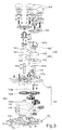
- the present invention relates to a massage device 100.
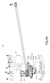
- the massage device 100 comprises (a) a base cover 110 having a first end portion 113 and an opposite, second end portion 114, a longitudinal axis 111 and multiple guiding rails 112 formed parallel to the longitudinal axis 111; (b) a carriage 130 having a chassis member 131 and a shield member 132 over the chassis member 131, the chassis member 131 having multiple grooves 134 formed in the bottom surface, and at least one tab 131b protruded from one end portion 131a of the chassis member 131, the at least one tab 131b defining a hole 131c therein; wherein when the carriage 130 is engaged with the base cover 110, the guiding rails 112 is received in the grooves 134 of the chassis member 131, respectively, and the carriage 130 is movable back and forth along the guiding rails 112 of the base cover 110; and (c) a first transmission assembly140 secured in the carriage 130, the first transmission assembly 140 comprising at
- the massage device 100 further comprises a massage assembly having a pair of massage members 150.
- Each of the massage member 150 comprises (i) a gear shaft 151 having a first end portion 151a and an opposite, second end portion 151b, wherein the gear shaft 151 extends through the shield member 132 of the carriage 130 and is coaxially mounted to the corresponding worm gear 143a or 143b by the first end portion 151a; (ii) a driving member 160 having an eccentric wheel 161 and an eccentric block 167, wherein the eccentric wheel 161 has a first planar surface 161a, a second planar surface 161b tilted to the first planar surface 161a at an angle ⁇ , a third planar surface 161c parallel to the second planar surface 161b, a first cylindrical portion 162 defined between the first planar surface 161a and the second planar surface 161b, a second cylindrical portion 163 defined between the second planar surface 161b and the third planar surface 161c, and a shaft bore 164 defined
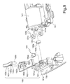
- the massage device 100 further has a locking mechanism 180.
- the locking mechanism 180 comprises (i) a base member 181 defining a bore 181b and at least one step-like recess 181a for releasably receiving the at least one tab 131b of the chassis member 131, the base member 181 being secured to the first end portion 113 of the a base cover 110; (ii) a cushion member 182 having a first opening 182a, and at least one second opening 182b, positioned over the base member 181 such that the first opening 182a and the at least one second opening 182b are respectively corresponding to the bore 181b and the at least one step-like recess 181a of the base member 181; (iii) a bolt member 183 having a body portion 183c, a peg 183a and at least one cylindrical column 183b respectively protruded from the body portion 183c, positioned over the cushion member 182 such that the peg 183a and the at least one cylindrical column 183
- the locking mechanism 180 is pre-set such that the at least one tab 131b of the chassis member 131 is received in the at least one step-like recess 181a of the base member 181; the peg 183a of the of the bolt member 183 is snapped, through the first opening 182a of the cushion member 182, into the bore 181b of the base member 181; the at least one cylindrical column 183b of the bolt member 183 is snapped, through the at least one second opening 182b of the cushion member 182 and the hole 131c of the at least one tab 131b of the chassis member 131, into the at least one step-like recess 181a of the base member 181; and the base portion 184a of the wedge member 184 is positioned under the cushion member 182 and releasably engaged with the bolt member 183, thereby locking the chassis member 131 from moving.
- the eccentric block 185 rotates around the output shaft 141a of the first motor 141, and the rotation of the eccentric block 185 causes the protrusion 185a to push the side portion 184b of the wedge member 184 to move towards a position limit point of the cushion member 182 so as to eject the bolt member 183, thereby releasing the at least one tab 131b of the chassis member 131 from the base member 181 of the locking mechanism 180.
- the massage device 100 further includes a second transmission assembly 170 engaged with the first transmission assembly 140.
- the second transmission assembly 170 comprising a hoist transmission mechanism 175, a second motor 171 having an output shaft 171a, a second worm 172 mechanically coupled with the output shaft 171a of the second motor 171, one or more worm gears 173 mechanically coupled with the second worm 172 and the hoist transmission mechanism 175 such that when the second motor 171 is activated, it drives the second worm 172 to rotate, the rotation of the second worm 172 results in, in turn, the rotations of the one or more worm gears 173, thereby moving the carriage 130 along the guiding rails 112 of the base cover 110.
- each massage members 150 comprises an energy source of capable of generating at least one of thermal energy and photonic energy, where the energy source comprises a lamp base, a PCB board attached to the lamp base, and heating lamps attached onto the PCB board.
- the massage device 100 further comprise a remote controller 190 for emit a wireless signal; and a circuit board 195 connected to first motor 141 and the second motor 171 and adopted to receive the wireless signal, wherein based on the received wireless signal, the at least one of the first motor 141 and the second motor 171 is activated by the circuit board 195.
- this invention in one aspect, relates to a locking mechanism to releasably lock the massage assemblies from moving.
- the massage device 100 includes a base cover 110, a carriage 130, a transmission assembly comprising a first transmission assembly 140 and a second transmission assembly 170, a massage assembly having a pair of massage members 150, and a locking mechanism 180.
- the base cover 110 has a first end portion 113, an opposite, second end portion 114, a longitudinal axis 111 and two guiding rails 112 formed parallel to the longitudinal axis 111.
- the two guiding rails 112 are adapted for cooperating with the carriage 130 and translating the pair of massage members 150 along the longitudinal axis 111.
- Other numbers of guiding rails can also be utilized to practice the present invention.
- the base cover 110 may also have a series of ribs 115 and supporting structures 116 for supporting and securing a top cover (cushion) to form a housing for accommodating the carriage 130, the first transmission assembly 140 and the massage assembly therein.
- the base cover 110 is made of a durable material, such as wood, plastic, alloy or the like.
- the carriage 130 includes a chassis member 131 having an end portion 131a and at least one tab 131b protruded from the end portion 131a, where the at least one tab 131b defines a hole 131c therein, and a shield member 132.
- the shield member 132 is placed over the chassis member 131 to form a chamber between the chassis member 131 and the shield member 132.
- the chassis member 131 has two grooves 134 spaced-apart and formed on the bottom surface of the chassis member 131. The two grooves 134 are configured and sized to receive the two guiding rails 112 of the base cover 110, respectively.
- the cooperation of the guiding rails 112 of the base cover 110 and the grooves 134 of the chassis member 131 provides longitudinal guidance and support to the carriage 130 as it translates along the guiding rails 112. That is, when the carriage 130 is engaged with the base cover 110, the guiding rails 112 are respectively received in the grooves 134 of the chassis member 131, respectively, and the carriage 130 is longitudinally movable back and forth along the guiding rails 112 of the base cover 110.
- Other numbers of grooves can also be utilized to practice the present invention.
- the number of grooves 134 is corresponding to the number of guiding rails 112 formed in the base cover 110.
- the first transmission assembly 140 is secured in the carriage 130.
- the transmission assembly 140 has a first motor 141 having an output shaft 141a, a worm 142 mechanically coupled with the output shaft 141a of the first motor 141, a pair of worm gears 143a and 143b meshing with the worm 142.
- the first motor 141 when the first motor 141 is activated, it drives the worm 142 to rotate, the rotation of the worm 142 results in the rotations of the pair of worm gears 143a and 143b.
- the second transmission assembly 170 is engaged with the first transmission assembly 140.
- the second transmission assembly 170 includes a hoist transmission mechanism 175, a second motor 171 having an output shaft 171a, a second worm 172 mechanically coupled with the output shaft 171a of the second motor 171, and one or more worm gears 173 mechanically coupled with the second worm 172 and the hoist transmission mechanism 175.
- the one or more worm gears 173 have four gears 173a-173d mechanically coupled with one another.
- the first gear 173a is mechanically coupled to the second worm 172, while the fourth gear 173d mechanically coupled to the hoist transmission mechanism 175 through a shaft 174.
- the second motor 171 when the second motor 171 is activated, it drives the second worm 172 to rotate, the rotation of the second worm 172 results in, in turn, the rotations of the one or more worm gears 173, thereby moving the carriage 130 along the guiding rails 112 of the base cover 110.
- the massage assembly has a pair of massage members 150.
- Each massage member 150 has a gear shaft 151, a driving member 160, a massage bracket 152, two massage heads 157, and a U-shape fixture 159.
- the gear shaft 151 has a first end portion 151a and an opposite, second end portion 151b.
- the gear shaft 151 extends through the shield member 132 of the carriage 130 and is coaxially mounted to the corresponding worm gear 143a or 143b by the first end portion 151a. In other words, when the worm gear 143a or 143b rotate, it drives the corresponding gear shaft 151 to rotate accordingly.
- the massage bracket 152 includes a first surface 152a and an opposite, second surface 152b defining a bracket body 152c therebetween, a central axis 152d, a protrusion 155 laterally extending from the bracket body 152c, and two stumps 153 spaced-apart on the first surface 152b.
- the bracket body 152c defines an opening 154 therethrough in the central region.
- the two massage heads 157 are respectively attached to the two stumps 153 of the massage bracket 152.
- each of the massage heads 157 has a mushroom-shape.
- Each of the massage heads 157 includes a first structure 157a, a mushroom-shape node 157c and a second structure 157b placed between the first structure 157a and the mushroom-shape node 157c.
- Each massage head 157 may include an energy source capable of generating at least one of thermal energy and photonic energy.
- the energy source may include a lamp base mounted to the corresponding one of the stumps 153, a PCB board attached to the lamp base, and heating lamps attached onto the PCB board.
- the first structure 157a and the second structure 157b of a massage head 157 can be parts of the energy source.
- the driving member 160 includes an eccentric wheel 161 and an eccentric block 167.
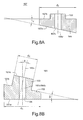
- the eccentric wheel 161 has a first planar surface 161a, a second planar surface 161b tilted to the first planar surface 161a at an angle ⁇ , a third planar surface 161c parallel to the second planar surface 161b, a first cylindrical portion 162 defined between the first planar surface 161a and the second planar surface 161b, a second cylindrical portion 163 defined between the second planar surface 161b and the third planar surface 161 c, and a shaft bore 164 defined through the first cylindrical portion 162 and the second cylindrical portion 163.
- the first cylindrical portion 162 has a central axis 162c substantially perpendicular to the first planar surface 161a, and a diameter, d 1 .
- the second cylindrical portion 163 has a central axis 163c substantially perpendicular to the second planar surface 161b and defining an angle ⁇ , relative to the central axis 162c of the first cylindrical portion 162, and a diameter, d 2 , less than the diameter d 1 of the first cylindrical portion 162.
- the shaft bore 164 has a central axis 164c substantially coincident with the central axis 162c of the first cylindrical portion 162.
- the eccentric block 167 has a first planar surface 167a and a second planar surface 167b defining a cylinder body 168 therebetween.
- the first planar surface 167a is tilted to the second planar surface 167b at an angle ⁇ .
- the angels ⁇ , ⁇ and ⁇ can also be chosen with other valves, same or different.
- the cylinder body 168 has a central axis 168c and a diameter, d 3 , greater than the diameter d 2 of the second cylindrical portion 163 of the eccentric wheel 161.
- the eccentric block 167 may have a head portion 169 extending from the second surface 167b, and a shaft bore 167c defined therethrough.
- the shaft bore 167c and the cylinder body 168 are substantially coaxial.
- the two massage heads 157 are respectively attached to the two stumps 153 of the massage bracket 152.
- the second cylindrical portion 163 of the eccentric wheel 161 is received in the opening 154 of the massage bracket 152.
- the eccentric block 167 is then attached onto the second cylindrical portion 163 of the eccentric wheel 161 such that the first planar surface 167a of the eccentric block 167 is substantially in contact with and parallel to the third planar surface 161c of the eccentric wheel 161, the central axis 168c of the cylinder body 168 of the eccentric block 167 is substantially coincident with the central axis 162c of the first cylindrical portion 162 of the eccentric wheel 160, the central axis 152d of the massage bracket 152 is substantially coincident with the central axis 163c of the second cylinder portion 163 of the eccentric wheel 160, the massage bracket 152 operably cooperates with the second cylindrical portion 163 of the eccentric wheel 161, and the shaft bore 164 of the eccentric wheel 161 and the shaft bore 167c of the eccentric block 167 are substantially coaxial.
- the protrusion 155 of the massage bracket 152 is received in the U-shape fixture 159 that in turn, is mounted to the shield member 132 of the carriage 130.
- the second end portion 151b of the gear shaft 151 is then secured into the shaft bore 164 such that when the gear shaft 151 rotates, it drives the driving member 160 to rotate accordingly.
- fastening means such as fastening pins 158 and screws 158a may be applied wherever it is needed to secure various components of the massage device 100.
- the first motor 141 drives the pair of worm gears 143a and 143b to rotate in opposed rotational directions, which drives the driving member 160 of the massage assembly 150 to rotate. Since the protrusion 155 of the massage bracket 152 is placed in the U-shape fixture 159 that is mounted to the shield member 134 of the carriage 130, the rotation of the massage bracket 152 around the central axis 162c of the first cylindrical portion 162 of the eccentric wheel 160 is prohibited. Therefore, the rotation of the driving member 160 of the massage assembly 150 drives the massage bracket 152 to gyrate in a way so that its central axis 152d rotates around the central axis 162c of the first cylindrical portion 162 of the eccentric wheel 160 in the angle ⁇ .
- Such a gyro rotation of the massage bracket 152 causes the two massage heads 157 to move alternatively along a direction parallel to the central axis 162c of the first cylindrical portion 162 of the eccentric wheel 160.
- a simulated massaging effect is provided.
- the locking mechanism 180 includes a base member 181 defining a bore 181b and at least one step-like recess 181a for releasably receiving the at least one tab 131b of the chassis member 131.
- the base member 181 is secured to the first end portion 113 of the base cover 110 for releasably locking the carriage 130.
- the locking mechanism 180 also includes a cushion member 182 having a first opening 182a, and at least one second opening 182b, positioned over the base member 181 such that the first opening 182a and the at least one second opening 182b are respectively corresponding to the bore 181b and the at least one step-like recess 181a of the base member 181.
- the locking mechanism 180 includes a bolt member 183 having a body portion 183c, and a peg 183a and at least one cylindrical column 183b respectively protruded from the body portion 183c, positioned over the cushion member 182 such that the peg 183a and the at least one cylindrical column 183b are respectively corresponding to the first opening 182a and the at least one second opening 182b of the cushion member 182.
- the locking mechanism 180 includes a wedge member 184 including a base portion 184a and a side portion 184b extending at an angle from the base portion 184a, positioned such that the base portion 184a is under the cushion member 182 and operably engaged with the bolt member 183.
- the locking mechanism 180 includes an eccentric block 185 having a protrusion 185a, engaged with the at least one first motor 141 such that the protrusion 185a is operably against to the side portion 184b of the wedge member 184.
- the locking mechanism 180 may also include an ejector positioned under the peg 183a of the bolt member 183.
- the wedge member 184 is formed in an L-like shape.
- the locking mechanism 180 is pre-set such that the at least one tab 131b of the chassis member 131 is received in the at least one step-like recess 181a of the base member 181; the peg 183a of the of the bolt member 183 is snapped, through the first opening 182a of the cushion member 182, into the bore 181b of the base member 181; the at least one cylindrical column 183b of the bolt member 183 is snapped, through the at least one second opening 182b of the cushion member 182 and the hole 131 c of the at least one tab 131b of the chassis member 131, into the at least one step-like recess 181a of the base member 181; and the base portion 184a of the wedge member 184 is positioned under the cushion member 182 and releasably engaged with the bolt member 183, thereby locking the chassis member 131 from moving.
- the eccentric block 185 rotates around the output shaft 141a of the first motor 141, and the rotation of the eccentric block 185 causes the protrusion 185a to push the side portion 184b of the wedge member 184 to move towards a position limit point of the cushion member 182 so as to eject the bolt member 183, thereby releasing the at least one tab 131b of the chassis member 131 from the base member 181 of the locking mechanism 180.
- the massage device 100 may further comprise a remote controller 190 and a circuit board 195 which is coupled to the first moter141 and the second motor 171 and adopted for receiving wireless signals emitted from the remote controller 190.
- a user is capable of activating the at least one the first motor 141 and the second motor 171 using the remote controller 190.
- the output shaft 171a of the second motor 171 may be controlled to rotate either clockwise or counter-clockwise so as to move carriage 130 along the guiding rails 112 and then stop the carriage 130 at a pre-determined position of the guiding rails 112.
- multiple sensors coupled the circuit board 195 may be arranged along a path parallel to the guiding rail 112 so as to divide the guiding rail 112 into several sections. Under this arrangement, a user is capable of using the remote controller 195 to activate the second motor 171 for moving the carriage 130 back and forth along the guiding rail 112 inside the selected section.
- the present invention recites a massage device that utilizes a locking mechanism to releasably lock the massage assemblies from moving.
- the present invention relates to a locking mechanism and a massage device of using same.
- the locking mechanism includes a base member secured to the a base cover of the massage device, a cushion member positioned over the base member, a bolt member positioned over the cushion member, a wedge member operably engaged with the bolt member, and an eccentric block engaged with the wedge member and a motor of the massage device.
- the locking mechanism is configured such that the carriage of the massage device is pre-locked against movements, and the activation of the motor unlocks the massage device.
Landscapes
- Health & Medical Sciences (AREA)
- Epidemiology (AREA)
- Pain & Pain Management (AREA)
- Physical Education & Sports Medicine (AREA)
- Rehabilitation Therapy (AREA)
- Life Sciences & Earth Sciences (AREA)
- Animal Behavior & Ethology (AREA)
- General Health & Medical Sciences (AREA)
- Public Health (AREA)
- Veterinary Medicine (AREA)
- Massaging Devices (AREA)
Priority Applications (2)
| Application Number | Priority Date | Filing Date | Title |
|---|---|---|---|
| EP20100168305 EP2272480A1 (de) | 2009-07-10 | 2010-07-02 | Massagevorrichtung mit Sperrmechanismus |
| EP10168761A EP2272484A1 (de) | 2009-07-10 | 2010-07-07 | Massagevorrichtung mit Abstandeinstellmechanismus für den Massagekopf |
Applications Claiming Priority (5)
| Application Number | Priority Date | Filing Date | Title |
|---|---|---|---|
| CN 200920133730 CN201469605U (zh) | 2009-07-10 | 2009-07-10 | 小脚丫形踩背按摩器 |
| US12/551,078 US8123708B2 (en) | 2004-05-11 | 2009-08-31 | Massage device |
| EP09169089A EP2272482A1 (de) | 2009-07-10 | 2009-08-31 | Massagevorrichtung |
| EP10157222A EP2368536B1 (de) | 2010-03-22 | 2010-03-22 | Massagevorrichtung mit Sperrmechanismus |
| EP20100168305 EP2272480A1 (de) | 2009-07-10 | 2010-07-02 | Massagevorrichtung mit Sperrmechanismus |
Publications (1)
| Publication Number | Publication Date |
|---|---|
| EP2272480A1 true EP2272480A1 (de) | 2011-01-12 |
Family
ID=42719255
Family Applications (1)
| Application Number | Title | Priority Date | Filing Date |
|---|---|---|---|
| EP20100168305 Withdrawn EP2272480A1 (de) | 2009-07-10 | 2010-07-02 | Massagevorrichtung mit Sperrmechanismus |
Country Status (1)
| Country | Link |
|---|---|
| EP (1) | EP2272480A1 (de) |
Cited By (2)
| Publication number | Priority date | Publication date | Assignee | Title |
|---|---|---|---|---|
| CN113599219A (zh) * | 2021-06-22 | 2021-11-05 | 惠州蒲公英健康科技有限公司 | 一种筋膜枪 |
| EP4248934A4 (de) * | 2020-11-19 | 2024-10-09 | Xiamen Comfier Technology Co., Ltd | Massagekopfanordnung |
Citations (4)
| Publication number | Priority date | Publication date | Assignee | Title |
|---|---|---|---|---|
| WO2008036955A2 (en) * | 2006-09-21 | 2008-03-27 | Human Touch, Llc | Kneading and rolling robotic massage device |
| EP2080499A1 (de) * | 2008-01-15 | 2009-07-22 | Weightec Electronic Technology Co., Ltd. | Massagegerät |
| US8201605B2 (en) | 2004-04-13 | 2012-06-19 | Manroland Druckmaschinen AG | Printing machine comprising an embossing device |
| US10378508B2 (en) | 2014-02-14 | 2019-08-13 | Lm Wp Patent Holding A/S | Bulkhead assembly for a wind turbine blade |
-
2010
- 2010-07-02 EP EP20100168305 patent/EP2272480A1/de not_active Withdrawn
Patent Citations (4)
| Publication number | Priority date | Publication date | Assignee | Title |
|---|---|---|---|---|
| US8201605B2 (en) | 2004-04-13 | 2012-06-19 | Manroland Druckmaschinen AG | Printing machine comprising an embossing device |
| WO2008036955A2 (en) * | 2006-09-21 | 2008-03-27 | Human Touch, Llc | Kneading and rolling robotic massage device |
| EP2080499A1 (de) * | 2008-01-15 | 2009-07-22 | Weightec Electronic Technology Co., Ltd. | Massagegerät |
| US10378508B2 (en) | 2014-02-14 | 2019-08-13 | Lm Wp Patent Holding A/S | Bulkhead assembly for a wind turbine blade |
Cited By (2)
| Publication number | Priority date | Publication date | Assignee | Title |
|---|---|---|---|---|
| EP4248934A4 (de) * | 2020-11-19 | 2024-10-09 | Xiamen Comfier Technology Co., Ltd | Massagekopfanordnung |
| CN113599219A (zh) * | 2021-06-22 | 2021-11-05 | 惠州蒲公英健康科技有限公司 | 一种筋膜枪 |
Similar Documents
| Publication | Publication Date | Title |
|---|---|---|
| US8062240B2 (en) | Massage device | |
| US8070698B2 (en) | Massage device with a shaft transmission mechanism | |
| US8083697B2 (en) | Massage device with a threaded bolt transmission mechanism | |
| US8066652B2 (en) | Massage device with a hoist transmission mechanism | |
| US20100268132A1 (en) | Massage device | |
| US8123708B2 (en) | Massage device | |
| US20120123462A1 (en) | Tattooing device | |
| US20170079865A1 (en) | Device for massage | |
| CN114041989B (zh) | 可变振幅筋膜枪及其驱动机构 | |
| JP7579602B2 (ja) | 超音波医療用カートリッジ、これを含む超音波医療装置およびバックラッシュ防止装置 | |
| US6723060B2 (en) | Vibrator | |
| US8083698B2 (en) | Massage device with a hoist transmission mechanism | |
| KR20090131673A (ko) | 문신장치 | |
| EP2368536B1 (de) | Massagevorrichtung mit Sperrmechanismus | |
| CA2568509C (en) | Water-resistant devices incorporating a switch assembly | |
| US20110184324A1 (en) | Massage device | |
| CN211326645U (zh) | 一种颈部按摩器 | |
| KR20190118460A (ko) | 피부시술용 멀티니들모듈을 위한 자동시술장치 | |
| JP2005284130A (ja) | レンズ移動機構 | |
| EP2272482A1 (de) | Massagevorrichtung | |
| CN114432115B (zh) | 筋膜枪及用于筋膜枪的直线往复式驱动机构 | |
| CN220442889U (zh) | 一种可调节的按摩器及按摩枕垫 | |
| CN217366470U (zh) | 小腿按摩机构 | |
| EP2272483A1 (de) | Massagevorrichtung | |
| KR102057496B1 (ko) | 휴대용 안마기 |
Legal Events
| Date | Code | Title | Description |
|---|---|---|---|
| PUAI | Public reference made under article 153(3) epc to a published international application that has entered the european phase |
Free format text: ORIGINAL CODE: 0009012 |
|
| AK | Designated contracting states |
Kind code of ref document: A1 Designated state(s): AL AT BE BG CH CY CZ DE DK EE ES FI FR GB GR HR HU IE IS IT LI LT LU LV MC MK MT NL NO PL PT RO SE SI SK SM TR |
|
| AX | Request for extension of the european patent |
Extension state: BA ME RS |
|
| 17P | Request for examination filed |
Effective date: 20110330 |
|
| STAA | Information on the status of an ep patent application or granted ep patent |
Free format text: STATUS: THE APPLICATION HAS BEEN WITHDRAWN |
|
| 18W | Application withdrawn |
Effective date: 20130628 |