EP2080499A1 - Massagegerät - Google Patents
Massagegerät Download PDFInfo
- Publication number
- EP2080499A1 EP2080499A1 EP08007470A EP08007470A EP2080499A1 EP 2080499 A1 EP2080499 A1 EP 2080499A1 EP 08007470 A EP08007470 A EP 08007470A EP 08007470 A EP08007470 A EP 08007470A EP 2080499 A1 EP2080499 A1 EP 2080499A1
- Authority
- EP
- European Patent Office
- Prior art keywords
- massage
- central axis
- cylindrical portion
- planar surface
- gear
- Prior art date
- Legal status (The legal status is an assumption and is not a legal conclusion. Google has not performed a legal analysis and makes no representation as to the accuracy of the status listed.)
- Granted
Links
- 230000005540 biological transmission Effects 0.000 claims abstract description 22
- 230000000694 effects Effects 0.000 claims abstract description 14
- 238000010438 heat treatment Methods 0.000 claims description 5
- 238000004898 kneading Methods 0.000 description 9
- 230000004048 modification Effects 0.000 description 4
- 238000012986 modification Methods 0.000 description 4
- 239000000956 alloy Substances 0.000 description 2
- 229910045601 alloy Inorganic materials 0.000 description 2
- 239000000463 material Substances 0.000 description 2
- 239000004033 plastic Substances 0.000 description 2
- 239000002023 wood Substances 0.000 description 2
- 230000007812 deficiency Effects 0.000 description 1
- 210000003205 muscle Anatomy 0.000 description 1
Images





Classifications
-
- A—HUMAN NECESSITIES
- A61—MEDICAL OR VETERINARY SCIENCE; HYGIENE
- A61H—PHYSICAL THERAPY APPARATUS, e.g. DEVICES FOR LOCATING OR STIMULATING REFLEX POINTS IN THE BODY; ARTIFICIAL RESPIRATION; MASSAGE; BATHING DEVICES FOR SPECIAL THERAPEUTIC OR HYGIENIC PURPOSES OR SPECIFIC PARTS OF THE BODY
- A61H7/00—Devices for suction-kneading massage; Devices for massaging the skin by rubbing or brushing not otherwise provided for
- A61H7/002—Devices for suction-kneading massage; Devices for massaging the skin by rubbing or brushing not otherwise provided for by rubbing or brushing
- A61H7/004—Devices for suction-kneading massage; Devices for massaging the skin by rubbing or brushing not otherwise provided for by rubbing or brushing power-driven, e.g. electrical
-
- A—HUMAN NECESSITIES
- A61—MEDICAL OR VETERINARY SCIENCE; HYGIENE
- A61H—PHYSICAL THERAPY APPARATUS, e.g. DEVICES FOR LOCATING OR STIMULATING REFLEX POINTS IN THE BODY; ARTIFICIAL RESPIRATION; MASSAGE; BATHING DEVICES FOR SPECIAL THERAPEUTIC OR HYGIENIC PURPOSES OR SPECIFIC PARTS OF THE BODY
- A61H1/00—Apparatus for passive exercising; Vibrating apparatus; Chiropractic devices, e.g. body impacting devices, external devices for briefly extending or aligning unbroken bones
-
- A—HUMAN NECESSITIES
- A61—MEDICAL OR VETERINARY SCIENCE; HYGIENE
- A61H—PHYSICAL THERAPY APPARATUS, e.g. DEVICES FOR LOCATING OR STIMULATING REFLEX POINTS IN THE BODY; ARTIFICIAL RESPIRATION; MASSAGE; BATHING DEVICES FOR SPECIAL THERAPEUTIC OR HYGIENIC PURPOSES OR SPECIFIC PARTS OF THE BODY
- A61H37/00—Accessories for massage
-
- A—HUMAN NECESSITIES
- A61—MEDICAL OR VETERINARY SCIENCE; HYGIENE
- A61H—PHYSICAL THERAPY APPARATUS, e.g. DEVICES FOR LOCATING OR STIMULATING REFLEX POINTS IN THE BODY; ARTIFICIAL RESPIRATION; MASSAGE; BATHING DEVICES FOR SPECIAL THERAPEUTIC OR HYGIENIC PURPOSES OR SPECIFIC PARTS OF THE BODY
- A61H7/00—Devices for suction-kneading massage; Devices for massaging the skin by rubbing or brushing not otherwise provided for
- A61H7/007—Kneading
- A61H2007/009—Kneading having massage elements rotating on parallel output axis
-
- A—HUMAN NECESSITIES
- A61—MEDICAL OR VETERINARY SCIENCE; HYGIENE
- A61H—PHYSICAL THERAPY APPARATUS, e.g. DEVICES FOR LOCATING OR STIMULATING REFLEX POINTS IN THE BODY; ARTIFICIAL RESPIRATION; MASSAGE; BATHING DEVICES FOR SPECIAL THERAPEUTIC OR HYGIENIC PURPOSES OR SPECIFIC PARTS OF THE BODY
- A61H2201/00—Characteristics of apparatus not provided for in the preceding codes
- A61H2201/01—Constructive details
- A61H2201/0119—Support for the device
- A61H2201/0138—Support for the device incorporated in furniture
-
- A—HUMAN NECESSITIES
- A61—MEDICAL OR VETERINARY SCIENCE; HYGIENE
- A61H—PHYSICAL THERAPY APPARATUS, e.g. DEVICES FOR LOCATING OR STIMULATING REFLEX POINTS IN THE BODY; ARTIFICIAL RESPIRATION; MASSAGE; BATHING DEVICES FOR SPECIAL THERAPEUTIC OR HYGIENIC PURPOSES OR SPECIFIC PARTS OF THE BODY
- A61H2201/00—Characteristics of apparatus not provided for in the preceding codes
- A61H2201/01—Constructive details
- A61H2201/0119—Support for the device
- A61H2201/0138—Support for the device incorporated in furniture
- A61H2201/0149—Seat or chair
-
- A—HUMAN NECESSITIES
- A61—MEDICAL OR VETERINARY SCIENCE; HYGIENE
- A61H—PHYSICAL THERAPY APPARATUS, e.g. DEVICES FOR LOCATING OR STIMULATING REFLEX POINTS IN THE BODY; ARTIFICIAL RESPIRATION; MASSAGE; BATHING DEVICES FOR SPECIAL THERAPEUTIC OR HYGIENIC PURPOSES OR SPECIFIC PARTS OF THE BODY
- A61H2201/00—Characteristics of apparatus not provided for in the preceding codes
- A61H2201/02—Characteristics of apparatus not provided for in the preceding codes heated or cooled
- A61H2201/0207—Characteristics of apparatus not provided for in the preceding codes heated or cooled heated
-
- A—HUMAN NECESSITIES
- A61—MEDICAL OR VETERINARY SCIENCE; HYGIENE
- A61H—PHYSICAL THERAPY APPARATUS, e.g. DEVICES FOR LOCATING OR STIMULATING REFLEX POINTS IN THE BODY; ARTIFICIAL RESPIRATION; MASSAGE; BATHING DEVICES FOR SPECIAL THERAPEUTIC OR HYGIENIC PURPOSES OR SPECIFIC PARTS OF THE BODY
- A61H2201/00—Characteristics of apparatus not provided for in the preceding codes
- A61H2201/02—Characteristics of apparatus not provided for in the preceding codes heated or cooled
- A61H2201/0221—Mechanism for heating or cooling
-
- A—HUMAN NECESSITIES
- A61—MEDICAL OR VETERINARY SCIENCE; HYGIENE
- A61H—PHYSICAL THERAPY APPARATUS, e.g. DEVICES FOR LOCATING OR STIMULATING REFLEX POINTS IN THE BODY; ARTIFICIAL RESPIRATION; MASSAGE; BATHING DEVICES FOR SPECIAL THERAPEUTIC OR HYGIENIC PURPOSES OR SPECIFIC PARTS OF THE BODY
- A61H2201/00—Characteristics of apparatus not provided for in the preceding codes
- A61H2201/12—Driving means
- A61H2201/1207—Driving means with electric or magnetic drive
- A61H2201/1215—Rotary drive
-
- A—HUMAN NECESSITIES
- A61—MEDICAL OR VETERINARY SCIENCE; HYGIENE
- A61H—PHYSICAL THERAPY APPARATUS, e.g. DEVICES FOR LOCATING OR STIMULATING REFLEX POINTS IN THE BODY; ARTIFICIAL RESPIRATION; MASSAGE; BATHING DEVICES FOR SPECIAL THERAPEUTIC OR HYGIENIC PURPOSES OR SPECIFIC PARTS OF THE BODY
- A61H2201/00—Characteristics of apparatus not provided for in the preceding codes
- A61H2201/14—Special force transmission means, i.e. between the driving means and the interface with the user
- A61H2201/1481—Special movement conversion means
- A61H2201/149—Special movement conversion means rotation-linear or vice versa
-
- A—HUMAN NECESSITIES
- A61—MEDICAL OR VETERINARY SCIENCE; HYGIENE
- A61H—PHYSICAL THERAPY APPARATUS, e.g. DEVICES FOR LOCATING OR STIMULATING REFLEX POINTS IN THE BODY; ARTIFICIAL RESPIRATION; MASSAGE; BATHING DEVICES FOR SPECIAL THERAPEUTIC OR HYGIENIC PURPOSES OR SPECIFIC PARTS OF THE BODY
- A61H2201/00—Characteristics of apparatus not provided for in the preceding codes
- A61H2201/16—Physical interface with patient
- A61H2201/1657—Movement of interface, i.e. force application means
- A61H2201/1664—Movement of interface, i.e. force application means linear
- A61H2201/1669—Movement of interface, i.e. force application means linear moving along the body in a reciprocating manner
-
- A—HUMAN NECESSITIES
- A61—MEDICAL OR VETERINARY SCIENCE; HYGIENE
- A61H—PHYSICAL THERAPY APPARATUS, e.g. DEVICES FOR LOCATING OR STIMULATING REFLEX POINTS IN THE BODY; ARTIFICIAL RESPIRATION; MASSAGE; BATHING DEVICES FOR SPECIAL THERAPEUTIC OR HYGIENIC PURPOSES OR SPECIFIC PARTS OF THE BODY
- A61H2201/00—Characteristics of apparatus not provided for in the preceding codes
- A61H2201/16—Physical interface with patient
- A61H2201/1683—Surface of interface
- A61H2201/169—Physical characteristics of the surface, e.g. material, relief, texture or indicia
- A61H2201/1692—Enhanced rubbing effect
-
- A—HUMAN NECESSITIES
- A61—MEDICAL OR VETERINARY SCIENCE; HYGIENE
- A61H—PHYSICAL THERAPY APPARATUS, e.g. DEVICES FOR LOCATING OR STIMULATING REFLEX POINTS IN THE BODY; ARTIFICIAL RESPIRATION; MASSAGE; BATHING DEVICES FOR SPECIAL THERAPEUTIC OR HYGIENIC PURPOSES OR SPECIFIC PARTS OF THE BODY
- A61H7/00—Devices for suction-kneading massage; Devices for massaging the skin by rubbing or brushing not otherwise provided for
Definitions
- the present invention relates generally to a massage device, and more particularly to a massage device that utilizes a gyro mechanism to provide massaging effects.
- Simulated massaging or kneading of parts of the body to aid circulation or relax the muscles has gained popularity, particularly, among people who are lack of exercise.
- the simulated massaging or kneading effects can be achieved electromagnetically and/or mechanically by means of a massage device.
- a massage device For the electromagnetic massaging or kneading, such a massage device is configured to generate a series of electromagnetic pulses, which are regularly directed to parts of interest of the body so as to perform massaging or kneading thereon.
- the massaging or kneading area of the massage device is limited, and the massaging or kneading effects may not be very gentle.
- the massage device is usually designed to have a plurality of massage nodes and a driving system to drive the plurality of massage nodes to rotate so as to simulate massaging or kneading when applied to parts of interest of the body.
- a driving system to drive the plurality of massage nodes to rotate so as to simulate massaging or kneading when applied to parts of interest of the body.
- the limitation of the massaging or kneading area is improved for the mechanical massaging.
- mechanical massage devices are relatively complex and costly.
- the massage device in one aspect, relates to a massage device.
- the massage device includes a base cover having a longitudinal axis and a plurality of guiding rails formed parallel to the longitudinal axis, and a rack mounted to the base cover and paralleled to the plurality of guiding rails.
- the massage device further includes a carriage having a chassis member and a shield member placed over the chassis member to form a chamber therebetween, wherein the chassis member has a plurality of grooves formed such that when the carriage is engaged with the base cover, the plurality of guiding rails is received in the plurality of grooves of the chassis member and the carriage is longitudinally movable back and forth along the plurality of guiding rails of the base cover.
- the massage device also includes a transmission assembly received in the chamber and secured in the carriage.
- the transmission assembly includes a motor having an output shaft, a worm mechanically coupled with the output shaft of the motor, a pair of worm wheels meshing with the worm, a first gear coaxially mounted under one of the pair of worm wheels, a second gear meshing with the first gear, a pinion gear coaxially extended under the second gear, a third gear meshing with the pinion gear, and a driving gear coaxially extended under the third gear and meshing with the rack such that when the motor is activated, it drives the worm to rotate, the rotation of the worm results in, in turn, the rotations of the pair of worm wheels, the first gear, the second gear, the pinion gear, the third gear and the driving gear, thereby moving the carriage along the plurality of the guiding rails of the base cover.
- the massage device includes a massage assembly having a pair of massage members.
- Each massage member has a gear shaft, a driving member, a massage bracket, a plurality of massage heads, and a U-shape fixture.
- the gear shaft has a first end portion and an opposite, second end portion.
- the gear shaft extends through the shield member of the carriage and is coaxially mounted to the corresponding worm wheel by the first end portion.
- the driving member includes an eccentric wheel and an eccentric block.
- the eccentric wheel has a first planar surface, a second planar surface tilted to the first planar surface at an angle ⁇ , a third planar surface parallel to the second planar surface, a first cylindrical portion defined between the first planar surface and the second planar surface, a second cylindrical portion defined between the second planar surface and the third planar surface, and a shaft bore defmed through the first cylindrical portion and the second cylindrical portion.
- the first cylindrical portion has a central axis substantially perpendicular to the first planar surface, and a diameter, d 1 .
- the second cylindrical portion has a central axis substantially perpendicular to the second planar surface and defining an angle ⁇ , relative to the central axis of the first cylindrical portion, and a diameter, d 2 , less than the diameter d 1 of the first cylindrical portion.
- the shaft bore has a central axis substantially coincident with the central axis of the first cylindrical portion.
- the eccentric block has a first planar surface and a second planar surface defining a cylinder body therebetween.
- the cylinder body has a central axis and a diameter, d 3 , greater than the diameter d 2 of the second cylindrical portion of the eccentric wheel, and the first planar surface is tilted to the second planar surface at an angle ⁇ .
- the massage bracket includes a first surface and an opposite, second surface defining a bracket body therebetween, a central axis, a protrusion laterally extending from the bracket body, and a plurality of stumps spaced-apart on the first surface, wherein the bracket body defines an opening therethrough.
- each of the plurality of massage heads has a mushroom-shape.
- Each of the plurality of massage heads has a first structure, a mushroom-shape node and a second structure placed between the first structure and the mushroom-shape node.
- each of the plurality of massage heads includes an energy source of capable of generating thermal energy.
- the source energy may include a lamp base mounted to the corresponding one of the plurality of stumps, a PCB board attached to the lamp base, and heating lamps attached onto the PCB board.
- each of the plurality of massage heads is attached to a corresponding one of the plurality of stumps of the massage bracket, respectively.
- the second cylindrical portion of the eccentric wheel is received in the opening of the massage bracket.
- the eccentric block is mounted to the second cylindrical portion of the eccentric wheel such that the first planar surface of the eccentric block is substantially in contact with and parallel to the third planar surface of the eccentric wheel, the central axis of the cylinder body of the eccentric block is substantially coincident with the central axis of the first cylindrical portion of the eccentric wheel, the central axis of the massage bracket is substantially coincident with the central axis of the second cylinder portion of the eccentric wheel, and the massage bracket operably cooperates with the second cylindrical portion of the eccentric wheel.
- the protrusion of the massage bracket is received in the U-shape fixture that in turn, is mounted to the shield member of the carriage.
- the second end portion of the gear shaft is received in the shaft bore.
- the motor drives the pair of worm wheels to rotate in opposed rotational directions, which in turn, drives the carriage to move along the plurality of the guiding rails of the base cover and the driving member of the massage assembly to rotate
- the rotation of the driving member of the massage assembly drives the massage bracket to gyrate in a way of which its central axis rotates along the central axis of the first cylindrical portion of the eccentric wheel in the angle ⁇ , thereby causing the plurality of massage heads to move alternatively along a direction parallel to the central axis of the first cylindrical portion of the eccentric wheel so as to provide a massage effect to a user.
- the present invention relates to a massage device.
- the massage device includes a base cover, a rack, a carriage, a transmission assembly and a massage assembly.
- the base cover has a longitudinal axis and a plurality of guiding rails formed parallel to the longitudinal axis.
- the rack is mounted to the base cover and paralleled to the plurality of guiding rails.
- the carriage includes a chassis member and a shield member placed over the chassis member to form a chamber therebetween.
- the chassis member has a plurality of grooves formed such that when the carriage is engaged with the base cover, the plurality of guiding rails is received in the plurality of grooves of the chassis member and the carriage is longitudinally movable back and forth along the plurality of guiding rails of the base cover.
- the transmission assembly is received in the chamber and secured in the carriage.
- the transmission assembly includes a motor having an output shaft, a worm mechanically coupled with the output shaft of the motor, a pair of first worm wheels meshing with the worm, a pair of second worm wheels each meshing with one of the pair of first worm wheels, a first gear coaxially mounted under one of the pair of second worm wheels, a second gear meshing with the first gear, a third gear meshing with both the second gear and the rack.
- the motor when the motor is activated, it drives the worm to rotate, the rotation of the worm results in, in turn, the rotations of the pair of worm wheels, the first gear, the second gear, the pinion gear, the third gear and the driving gear, thereby moving the carriage along the plurality of the guiding rails of the base cover.
- the massage assembly has a pair of massage members.
- Each massage member includes:
- the plurality of massage heads is attached to the plurality of stumps of the massage bracket, respectively.
- the second cylindrical portion of the eccentric wheel is received in the first opening of the massage bracket.
- the eccentric block is mounted to the second cylindrical portion of the eccentric wheel such that the first planar surface of the eccentric block is substantially in contact with and parallel to the third planar surface of the eccentric wheel, the central axis of the cylinder body of the eccentric block is substantially coincident with the central axis of the first cylindrical portion of the eccentric wheel, the central axis of the massage bracket is substantially coincident with the central axis of the second cylinder portion of the eccentric wheel, and the massage bracket operably cooperates with the second cylindrical portion of the eccentric wheel.
- the fixture bar is received in the second opening of the massage bracket and mounted to the shield member of the carriage at its one end. Additionally, the second end portion of the gear shaft is received in the shaft bore.
- the motor drives the pair of first worm wheels to rotate in opposed rotational directions, which in turn, drives the carriage to move along the plurality of the guiding rails of the base cover and the driving member of the massage assembly to rotate.
- the rotation of the driving member of the massage assembly drives the massage bracket to gyrate in a way of which its central axis rotates along the central axis of the first cylindrical portion of the eccentric wheel in the angle ⁇ , thereby causing the plurality of massage heads to move alternatively along a direction parallel to the central axis of the first cylindrical portion of the eccentric wheel so as to provide a massage effect to a user.
- each of the plurality of massage heads has a mushroom-shape.
- Each of the plurality of massage heads has a first structure, a mushroom-shape node and a second structure placed between the first structure and the mushroom-shape node.
- each of the plurality of massage heads includes an energy source of capable of generating thermal energy.
- the source energy may include a lamp base mounted to the corresponding one of the plurality of stumps, a PCB board attached to the lamp base, and heating lamps attached onto the PCB board.
- the present invention relates to a massage device.
- the massage device includes a massage assembly having a pair of massage members.
- Each massage member has a driving member having an eccentric wheel and an eccentric block, a massage bracket and a plurality of massage heads.
- the eccentric wheel has a first planar surface, a second planar surface tilted to the first planar surface at an angle ⁇ , a third planar surface parallel to the second planar surface, a first cylindrical portion defined between the first planar surface and the second planar surface, a second cylindrical portion defined between the second planar surface and the third planar surface, and a shaft bore defined through the first cylindrical portion and the second cylindrical portion.
- the first cylindrical portion has a central axis substantially perpendicular to the first planar surface, and a diameter, d 1 .
- the second cylindrical portion has a central axis substantially perpendicular to the second planar surface and defining an angle ⁇ , relative to the central axis of the first cylindrical portion, and a diameter, d 2 , less than the diameter d 1 of the first cylindrical portion.
- the shaft bore has a central axis substantially coincident with the central axis of the first cylindrical portion.
- the eccentric block has a first planar surface and a second planar surface defining a cylinder body therebetween.
- the cylinder body has a central axis and a diameter, d 3 , greater than the diameter d 2 of the second cylindrical portion of the eccentric wheel, and the first planar surface is tilted to the second planar surface at an angle ⁇ .
- the massage bracket has a first surface and an opposite, second surface defining a bracket body therebetween, a central axis and a plurality of stumps spaced-apart on the first surface.
- the bracket body defines an opening therethrough in the central region.
- each of the plurality of massage heads is attached to a corresponding one of the plurality of stumps of the massage bracket, respectively, the second cylindrical portion of the eccentric wheel is received in the opening of the massage bracket.
- the eccentric block is mounted to the second cylindrical portion of the eccentric wheel such that the first planar surface of the eccentric block is substantially in contact with and parallel to the third planar surface of the eccentric wheel, the central axis of the cylinder body of the eccentric block is substantially coincident with the central axis of the first cylindrical portion of the eccentric wheel, the central axis of the massage bracket is substantially coincident with the central axis of the second cylinder portion of the eccentric wheel, and the massage bracket operably cooperates with the second cylindrical portion of the eccentric wheel.
- the massage device includes a base cover having a longitudinal axis and a plurality of guiding rails formed parallel to the longitudinal axis, and a rack mounted to the base cover and paralleled to the plurality of guiding rails.
- the massage device also includes a carriage having a chassis member and a shield member placed over the chassis member to form a chamber therebetween.
- the chassis member has a plurality of grooves formed such that when the carriage is engaged with the base cover, the plurality of guiding rails is received in the plurality of grooves of the chassis member and the carriage is longitudinally movable back and forth along the plurality of guiding rails of the base cover.
- the massage device includes a transmission assembly adapted for driving the plurality of massage heads to move alternatively along a first direction parallel to the central axis of the first cylindrical portion of the eccentric wheel, while translating the massage assembly along a second direction perpendicular to the first direction.
- the transmission assembly is received in the chamber and secured in the carriage.
- the transmission assembly includes a motor having an output shaft, a worm mechanically coupled with the output shaft of the motor, a pair of worm wheels meshing with the worm, a first gear coaxially mounted under one of the pair of worm wheels, a second gear meshing with the first gear, a pinion gear coaxially extended under the second gear, a third gear meshing with the pinion gear, and a driving gear coaxially extended under the third gear and meshing with the rack such that when the motor is activated, it drives the worm to rotate, the rotation of the worm results in, in turn, the rotations of the pair of worm wheels, the first gear, the second gear, the pinion gear, the third gear and the driving gear, thereby moving the carriage along the plurality of the guiding rails of the base cover.
- each massage member may include a gear shaft having a first end portion and an opposite, second end portion.
- the gear shaft extends through the shield member of the carriage and is coaxially mounted to the corresponding worm wheel by the first end portion, while secured into the shaft bore of the eccentric wheel by the second end portion.
- each massage member may include means for limiting the massage bracket from rotating along the central axis of the first cylindrical portion of the eccentric wheel.
- the limiting means comprises a U-shape fixture or a fixture bar mounted to the shield member of the carriage.
- the motor drives the pair of worm wheels to rotate in opposed rotational directions, which in turn, drives the carriage to move along the plurality of the guiding rails of the base cover and the driving member of the massage assembly to rotate.
- the rotation of the driving member of the massage assembly drives the massage bracket to gyrate in a way of which its central axis rotates along the central axis of the first cylindrical portion of the eccentric wheel in the angle ⁇ , thereby causing the plurality of massage heads to move alternatively along a direction parallel to the central axis of the first cylindrical portion of the eccentric wheel so as to provide a massage effect to a user.
- each massage member includes an eccentric wheel, an eccentric block, a massage bracket, and a plurality of massage heads.
- the eccentric wheel has a first planar surface, a second planar surface tilted to the first planar surface at an angle ⁇ , a third planar surface parallel to the second planar surface, a first cylindrical portion defined between the first planar surface and the second planar surface, a second cylindrical portion defined between the second planar surface and the third planar surface, and a shaft bore defined through the first cylindrical portion and the second cylindrical portion.
- the first cylindrical portion has a central axis substantially perpendicular to the first planar surface, and a diameter, d 1 .
- the second cylindrical portion has a central axis substantially perpendicular to the second planar surface and defining an angle ⁇ , relative to the central axis of the first cylindrical portion, and a diameter, d 2 , less than the diameter d 1 of the first cylindrical portion.
- the shaft bore has a central axis substantially coincident with the central axis of the first cylindrical portion.
- the eccentric block has a first planar surface and a second planar surface defining a cylinder body therebetween.
- the cylinder body has a central axis and a diameter, d 3 , greater than the diameter d 2 of the second cylindrical portion of the eccentric wheel, and the first planar surface is tilted to the second planar surface at an angle ⁇ .
- the massage bracket has a first surface and an opposite, second surface defming a bracket body therebetween, a central axis and a plurality of stumps spaced-apart on the first surface, where the bracket body defines an opening therethrough in the central region.
- the plurality of massage heads is attached to the plurality of stumps of the massage bracket, respectively, the second cylindrical portion of the eccentric wheel is received in the opening of the massage bracket.
- the eccentric block is mounted to the second cylindrical portion of the eccentric wheel such that the first planar surface of the eccentric block is substantially in contact with and parallel to the third planar surface of the eccentric wheel, the central axis of the cylinder body of the eccentric block is substantially coincident with the central axis of the first cylindrical portion of the eccentric wheel, the central axis of the massage bracket is substantially coincident with the central axis of the second cylinder portion of the eccentric wheel, and the massage bracket operably cooperates with the second cylindrical portion of the eccentric wheel.
- the massage assembly may further include means for limiting the massage bracket from rotating along the central axis of the first cylindrical portion of the eccentric wheel.
- the limiting means includes a U-shape fixture or a fixture bar.
- the present invention relates to a massage assembly usable for a massage device.
- the massage assembly includes a wheel member having a first surface, a second surface tilted at least to a part of the first surface, a third surface, a first body portion defined between the first surface and the second surface, a second body portion defined between the second surface and the third surface, and a shaft bore defined through the first body portion and the second body portion.
- the first body portion has a central axis relative to the first surface.
- the second body portion has a central axis relative to the second surface and defining an angle ⁇ relative to the central axis of the first body portion.
- the shaft bore has a central axis substantially coincident with the central axis of the first body portion.
- the massage assembly also includes a block member has a first surface that is configured to cooperate with the third surface of the wheel member and a second surface defining a body portion therebetween.
- the body portion has a central axis, and the first surface is tilted at least to a part of the second surface.
- the massage assembly also further includes a massage bracket and at least one massage head.
- the massage bracket has a first surface and an opposite, second surface defining a bracket body therebetween, a central axis and at least one stump on the first surface.
- the bracket body defines an opening therethrough.
- the at least one massage head is attached to the at least one stump of the massage bracket, the second body portion of the wheel member is received in the opening of the massage bracket, the block member is mounted to the second body portion of the wheel member such that the first surface of the block member is in contact with the third surface of the wheel member, the central axis of the body portion of the block member is substantially coincident with the central axis of the first body portion of the wheel member, the central axis of the massage bracket is substantially coincident with the central axis of the second body portion of the wheel member, and the massage bracket operably cooperates with the second body portion of the wheel member.
- this invention in one aspect, relates to a massage device that utilizes a gyro mechanism to provide massaging effects.
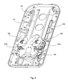
- the massage device 100 includes a base cover 110, a rack 120, a carriage 130, a transmission assembly 140 and a massage assembly having a pair of massage members 150.
- the base cover 110 has a longitudinal axis 111 and two guiding rails 112 formed parallel to the longitudinal axis 111.
- the two guiding rails 112 are adapted for cooperating with the carriage 130 and translating the pair of massage members 150 along the longitudinal axis 111.
- Other numbers of guiding rails can also be utilized to practice the present invention.
- the rack 120 is mounted to the base cover 110 and paralleled to the plurality of guiding rails 111.
- the base cover 110 may also have a series of ribs 113 and supporting structures 114 for supporting and securing a top cover 118 to form a housing for accommodating the carriage 130, the transmission assembly 140 and the massage assembly therein.
- the base cover 110 is made of a durable material, such as wood, plastic, alloy or the like.
- the carriage 130 includes a chassis member 131 and a shield member 132 placed over the chassis member 131 to form a chamber 133 therebetween.
- the chassis member 131 has two grooves 134 spaced-apart and formed on the bottom surface of the chassis member 131.
- the two grooves 134 are configured and sized to receive the two guiding rails 112 of the base cover 110, respectively.
- the cooperation of the guiding rails 112 of the base cover 110 and the grooves 134 of the chassis member 131 provides longitudinal guidance and support to the carriage 130 as it translates along the guiding rails 112.
- the guiding rails 112 are respectively received in the grooves 134 of the chassis member 131 and the carriage 130 is longitudinally movable back and forth along the plurality of guiding rails 112 of the base cover 110.
- Other numbers of grooves can also be utilized to practice the present invention. The number of grooves is corresponding to the number of guiding rails formed in the base cover 110.
- the transmission assembly 140 is received in the chamber 133 and secured in the carriage 130.
- the transmission assembly 140 has a motor 141 having an output shaft 141a, a worm 142 mechanically coupled with the output shaft 141 a of the motor 141, a pair of worm wheels 143a and 143b meshing with the worm 142, a first gear 144 coaxially mounted under one of the pair of worm wheels 143a or 143b, a second gear 145 meshing with the first gear 144, a pinion gear 145a coaxially extended under the second gear 145, a third gear 146 meshing with the pinion gear 145a, and a driving gear 146a coaxially extended under the third gear 146 and meshing with the rack 120.
- the motor 141 when the motor 141 is activated, it drives the worm 142 to rotate, the rotation of the worm 142 results in, in turn, the rotations of the pair of worm wheels 143a and 143b, the first gear 144, the second gear 145, the pinion gear 145a, the third gear 146 and the driving gear 146a, accordingly, thereby moving the carriage 130 along the rack 120, i.e., the guiding rails 112 of the base cover 110.
- the massage assembly has a pair of massage members 150.
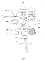
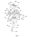
- Each massage member 150 has a gear shaft 151, a driving member 160, a massage bracket 152, three massage heads 157, and a U-shape fixture 159.
- the gear shaft 151 has a first end portion 151a and an opposite, second end portion 151b.
- the gear shaft 151 extends through the shield member 132 of the carriage 130 and is coaxially mounted to the corresponding worm wheel 143a or 143b by the first end portion 151a. In other words, when the worm wheel 143a or 143b rotate, it drives the corresponding gear shaft 151 to rotate accordingly.
- the massage bracket 152 includes a first surface 152a and an opposite, second surface 152b defining a bracket body 152c therebetween, a central axis 152d, a protrusion 155 laterally extending from the bracket body 152c, and three stumps 153 spaced-apart on the first surface 152b.
- the bracket body 152c defines an opening 154 therethrough in the central region.
- Three massage heads 157 are respectively attached to three stumps 153 of the massage bracket 152.
- each massage head 157 has a mushroom-shape.
- Each massage head 157 has a first structure 157a, a mushroom-shape node 157c and a second structure 157b placed between the first structure 157a and the mushroom-shape node 157c.
- Each massage head 157 may include an energy source capable of generating thermal energy.
- the source energy may include a lamp base mounted to the corresponding one of the plurality of stumps 153, a PCB board attached to the lamp base, and heating lamps attached onto the PCB board.
- the first structure 157a and the first structure 157a of a massage head 157 can be parts of the source energy.
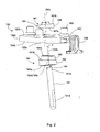
- the driving member 160 includes an eccentric wheel 161 and an eccentric block 167.
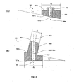
- the eccentric wheel 161 has a first planar surface 161a, a second planar surface 161b tilted to the first planar surface 161a at an angle ⁇ , a third planar surface 161c parallel to the second planar surface 161b, a first cylindrical portion 162 defined between the first planar surface 161a and the second planar surface 161b, a second cylindrical portion 163 defined between the second planar surface 161b and the third planar surface 161c, and a shaft bore 164 defined through the first cylindrical portion 162 and the second cylindrical portion 163.
- the first cylindrical portion 162 has a central axis 162c substantially perpendicular to the first planar surface 161a, and a diameter, d 1 .
- the second cylindrical portion 163 has a central axis 163c substantially perpendicular to the second planar surface 161b and defining an angle ⁇ , relative to the central axis 162c of the first cylindrical portion 162, and a diameter, d 2 , less than the diameter d 1 of the first cylindrical portion 162.
- the shaft bore 164 has a central axis 164c substantially coincident with the central axis 162c of the first cylindrical portion 162.
- the eccentric block 167 has a first planar surface 167a and a second planar surface 167b defining a cylinder body 168 therebetween.
- the first planar surface 167a is tilted to the second planar surface 167b at an angle ⁇ .
- the angels ⁇ , ⁇ and ⁇ can also be chosen with other valves, same or different.
- the cylinder body 168 has a central axis 168c and a diameter, d 3 , greater than the diameter d 2 of the second cylindrical portion 163 of the eccentric wheel 161.
- the eccentric block 167 may have a head portion 169 extending from the second surface 167b, and a shaft bore 167c defined therethrough.
- the shaft bore 167c and the cylinder body 168 are substantially coaxial.
- the three massage heads 157 are respectively attached to the three stumps 153 of the massage bracket 152.
- the second cylindrical portion 163 of the eccentric wheel 161 is received in the opening 154 of the massage bracket 152.
- the eccentric block 167 is then attached onto the second cylindrical portion 163 of the eccentric wheel 161 such that the first planar surface 167a of the eccentric block 167 is substantially in contact with and parallel to the third planar surface 161 c of the eccentric wheel 161, the central axis 168c of the cylinder body 168 of the eccentric block 167 is substantially coincident with the central axis 162c of the first cylindrical portion 162 of the eccentric wheel 160, the central axis 152d of the massage bracket 152 is substantially coincident with the central axis 163c of the second cylinder portion 163 of the eccentric wheel 160, the massage bracket 152 operably cooperates with the second cylindrical portion 163 of the eccentric wheel 161, and the shaft bore 164 of the eccentric wheel 161 and the shaft bore 167c of the eccentric block 167 are substantially coaxial
- the protrusion 155 of the massage bracket is received in the U-shape fixture 159 that in turn, is mounted to the shield member 132 of the carriage 130.
- the second end portion 151 b of the gear shaft 151 is then secured into the shaft bore 164 such that when the gear shaft 151 rotates, it drives the driving member 160 to rotate accordingly.
- fastening means such as fastening pins 158 and screws 158a may be applied wherever it is needed to secure various components of the massage device 100.
- the motor 141 drives the pair of worm wheels 143a and 143b to rotate in opposed rotational directions, which in turn, drives the carriage 130 to move along the plurality of the guiding rails 112 of the base cover 110 and the driving member 160 of the massage assembly 150 to rotate. Since the protrusion 155 of the massage bracket 152 is placed in the U-shape fixture 159 that is mounted to the shield member 134 of the carriage 130, the rotation of the massage bracket 152 around the central axis 162c of the first cylindrical portion 162 of the eccentric wheel 160 is prohibited.
- the rotation of the driving member 160 of the massage assembly 150 drives the massage bracket 152 to gyrate in a way so that its central axis 152d rotates around the central axis 162c of the first cylindrical portion 162 of the eccentric wheel 160 in the angle ⁇ .
- Such a gyro rotation of the massage bracket 152 causes the three massage heads 157 to move alternatively along a direction parallel to the central axis 162c of the first cylindrical portion 162 of the eccentric wheel 160.
- the massage device 200 includes a base cover 210, a rack 220, a carriage 230, a transmission assembly 240 and a massage assembly having a pair of massage members 150.
- the base cover 210 has a longitudinal axis 211 and two guiding rails 212 formed parallel to the longitudinal axis 211.
- the two guiding rails 212 are adapted for cooperating with the carriage 230 and translating the pair of massage members 250 along the longitudinal axis 211.
- Other numbers of guiding rails can also be utilized to practice the present invention.
- the rack 220 is mounted to the base cover 210 and paralleled to the plurality of guiding rails 211.
- the base cover 210 may also have a series of ribs 213 and supporting structures 214 for supporting and securing a top cover 218 to form a housing for accommodating the carriage 230, the transmission assembly 240 and the massage assembly therein.
- the base cover 210 is made of a durable material, such as wood, plastic, alloy or the like.
- the carriage 230 includes a chassis member 231 and a shield member 232 placed over the chassis member 231 to form a chamber 233 therebetween.
- the chassis member 231 has two grooves 234 spaced-apart formed on the bottom surface of the chassis member 231.
- the two grooves 234 are sized to receive the two guiding rails 212 of the base cover 210, respectively.
- the cooperation of the guiding rails 212 of the base cover 210 and the grooves 234 of the chassis member 231 provides longitudinal guidance and support to the carriage 230 as it translates along the guiding rails 212.
- the carriage 130 may also include a plurality of roller bearings 236, which are each pivotally connected to the carriage 130 and are offset from the grooves 234 and adjacent thereto for engaging a bearing surface provide upon each guiding rail 212 of the base cover 210. As the carriage 130 translates along the guiding rails 212, the carriage 130 is bearingly supported by the roller bearings 60 as they engage the surfaces provided by the guiding rails 212. Other numbers of grooves can also be utilized to practice the present invention. The number of grooves is corresponding to the number of guiding rails formed in the base cover 210.
- the transmission assembly 240 is received in the chamber 233 and secured in the carriage 230.
- the transmission assembly 240 includes a motor 241 having an output shaft 241a, a worm 242 mechanically coupled with the output shaft 241a of the motor 241, a pair of first worm wheels 243a and 243b meshing with the worm 242, a pair of second worm wheels 244a and 244b each meshing with a corresponding one of the pair of first worm wheels 243a and 243b, a first gear 244 coaxially mounted under one of the pair of second worm wheels 244a or 244b, a second gear 245 meshing with the first gear 244, a third gear 246 meshing with both the second gear 245 and the rack 220.
- the motor 241 when the motor 241 is activated, it drives the worm 242 to rotate, the rotation of the worm 242 results in, in turn, the rotations of the pair of first worm wheels 243a and 243b, the pair of second worm wheels 244a and 244b, the first gear 244, the second gear 245, the third gear 246, accordingly, thereby moving the carriage 230 along the plurality of the guiding rails of the base cover 210.
- the massage assembly has a pair of massage members 250.
- Each massage member 250 includes a gear shaft 251, a driving member 260, a massage bracket 252, two massage heads 257 attached to the massage bracket 252, and a fixture bar 259 mounted to the carriage 230.
- the gear shaft 251 having a first end portion 251a and an opposite, second end portion 251b.
- the gear shaft 251 extends through the shield member 232 of the carriage 230 and is coaxially mounted to a corresponding second worm wheel 244a or 244b by the first end portion 251a.
- the massage bracket 252 includes a first surface 252a and an opposite, second surface 252b defining a bracket body 252c therebetween, a central axis 252d and a plurality of stumps 253 spaced-apart on the first surface 252b.
- the bracket body 252c defines a first opening 254 in the central region and a second opening 255 in a region apart from the central region.
- Two massage heads 257 are respectively attached to two stumps 253 of the massage bracket 252. Each massage head 257 has a mushroom-shape. In this embodiment; as shown in Figs.
- each massage head 257 has a first structure 257a, a mushroom-shape node 257c and a second structure 257b placed between the first structure 257a and the mushroom-shape node 257c. Additionally, each massage head 257 may include an energy source capable of generating thermal energy.
- the driving member 260 has an eccentric wheel 261 and an eccentric block 267.
- the eccentric wheel 261 has a first planar surface 261a, a second planar surface 261b tilted to the first planar surface 261a at an angle ⁇ , a third planar surface 261c parallel to the second planar surface 261b, a first cylindrical portion 262 defined between the first planar surface 261 a and the second planar surface 261 b, a second cylindrical portion 263 defined between the second planar surface 261b and the third planar surface 261c, and a shaft bore 264 defined through the first cylindrical portion 262 and the second cylindrical portion 263, where the first cylindrical portion 262 has a central axis 262c substantially perpendicular to the first planar surface 261a, and a diameter, D 1 , where the second cylindrical portion 263 has a central axis 263c substantially perpendicular to the second planar surface 261b and defining an angle ⁇ , relative to the central axis 262c of the first
- the shaft bore 264 has a central axis 264c substantially coincident with the central axis 262c of the first cylindrical portion 262.
- the eccentric block 267 has a first planar surface 267a and a second planar surface 267b defining a cylinder body 268 therebetween.
- the first planar surface 267a is tilted to the second planar surface 267b at an angle ⁇ .
- the angels ⁇ , ⁇ and ⁇ can also be chosen with other values, same or different.
- the cylinder body 268 has a central axis 268c and a diameter, d 3 , greater than the diameter d 2 of the second cylindrical portion 263 of the eccentric wheel 261.
- the eccentric block 267 may have a shaft bore 267c defined therethrough.
- the shaft bore 267c and the cylinder body 268 are substantially coaxial.
- the three massage heads 257 are respectively attached to the three stumps 253 of the massage bracket 252.
- the second cylindrical portion 263 of the eccentric wheel 261 is received in the first opening 254 of the massage bracket 252.
- the eccentric block 267 is then attached onto the second cylindrical portion 263 of the eccentric wheel 261 such that the first planar surface 267a of the eccentric block 267 is substantially in contact with and parallel to the third planar surface 261 c of the eccentric wheel 261, the central axis 268c of the cylinder body 268 of the eccentric block 267 is substantially coincident with the central axis 262c of the first cylindrical portion 262 of the eccentric wheel 260, the central axis 252d of the massage bracket 252 is substantially coincident with the central axis 263c of the second cylinder portion 263 of the eccentric wheel 260, the massage bracket 252 operably cooperates with the second cylindrical portion 263 of the eccentric wheel 261, and the shaft bore 264 of the eccentric wheel 261 and the shaft bore 267c of the eccentric block 267 are substantially co
- the fixture bar 259 places into the second opening 255 of the massage bracket 252 and is mounted to the shield member 232 of the carriage 230.
- the second end portion 251b of the gear shaft 251 is then secured into the shaft bore 264 such that when the gear shaft 251 rotates, it drives the driving member 260 to rotate accordingly.
- fastening means such as fastening pins 258 and screws 258a may be applied wherever it is needed to secure various components of the massage device 200.
- the motor 241 drives the pair of first worm wheels 243a and 243b to rotate in opposed rotational directions, which in turn, drives the carriage 230 to move along the plurality of the guiding rails 212 of the base cover 210 and the driving member 260 of the massage assembly 250 to rotate. Since the second opening 255 of the massage bracket 252 receives in the fixture bar 259 that is mounted to the shield member 234 of the carriage 230, the rotation of the massage bracket 252 around the central axis 262c of the first cylindrical portion 262 of the eccentric wheel 260 is prohibited.
- the rotation of the driving member 260 of the massage assembly 250 will drive the massage bracket 252 to gyrate in a way so that its central axis 252d rotates around the central axis 262c of the first cylindrical portion 262 of the eccentric wheel 260 in the angle ⁇ .
- Such a gyro rotation of the massage bracket 252 causes the two massage heads 257 to move alternatively along a direction parallel to the central axis 262c of the first cylindrical portion 262 of the eccentric wheel 260.
- the massage assembly includes a wheel member having a first surface, a second surface tilted at least to a part of the first surface, a third surface, a first body portion defined between the first surface and the second surface, a second body portion defined between the second surface and the third surface, and a shaft bore defined through the first body portion and the second body portion.
- the first body portion has a central axis relative to the first surface.
- the second body portion has a central axis relative to the second surface and defining an angle ⁇ relative to the central axis of the first body portion.
- the shaft bore has a central axis substantially coincident with the central axis of the first body portion.
- the massage assembly also includes a block member that has a first surface that is configured to cooperate with the third surface of the wheel member and a second surface defining a body portion therebetween.
- the body portion has a central axis, and the first surface is tilted at least to a part of the second surface.
- the massage assembly also further includes a massage bracket and at least one massage head.
- the massage bracket has a first surface and an opposite, second surface defining a bracket body therebetween, a central axis and at least one stump on the first surface.
- the bracket body defines an opening therethrough.
- the at least one massage head is attached to the at least one stump of the massage bracket, the second body portion of the wheel member is received in the opening of the massage bracket, the block member is mounted to the second body portion of the wheel member such that the first surface of the block member is in contact with the third surface of the wheel member, the central axis of the body portion of the block member is substantially coincident with the central axis of the first body portion of the wheel member, the central axis of the massage bracket is substantially coincident with the central axis of the second body portion of the wheel member, and the massage bracket operably cooperates with the second body portion of the wheel member.
- the massage device includes a massage assembly and a transmission assembly for driving the massage assembly to provide massage effects.
- the massage assembly include a pair of massage members.
- Each massage member has a driving member having an eccentric wheel and an eccentric block, a massage bracket engaged with the driving member and a plurality of massage heads attached to the massage bracket.
Landscapes
- Health & Medical Sciences (AREA)
- Life Sciences & Earth Sciences (AREA)
- Epidemiology (AREA)
- Pain & Pain Management (AREA)
- Physical Education & Sports Medicine (AREA)
- Rehabilitation Therapy (AREA)
- Animal Behavior & Ethology (AREA)
- General Health & Medical Sciences (AREA)
- Public Health (AREA)
- Veterinary Medicine (AREA)
- Dermatology (AREA)
- Massaging Devices (AREA)
- Percussion Or Vibration Massage (AREA)
Priority Applications (2)
| Application Number | Priority Date | Filing Date | Title |
|---|---|---|---|
| PL08007470T PL2080499T3 (pl) | 2008-01-15 | 2008-04-16 | Urządzenie do masażu |
| EP10165243A EP2238961A1 (de) | 2008-01-15 | 2008-04-16 | Massagegerät |
Applications Claiming Priority (1)
| Application Number | Priority Date | Filing Date | Title |
|---|---|---|---|
| CNU2008200916164U CN201147462Y (zh) | 2008-01-15 | 2008-01-15 | 摇摆式按摩器 |
Publications (2)
| Publication Number | Publication Date |
|---|---|
| EP2080499A1 true EP2080499A1 (de) | 2009-07-22 |
| EP2080499B1 EP2080499B1 (de) | 2010-06-09 |
Family
ID=40115232
Family Applications (2)
| Application Number | Title | Priority Date | Filing Date |
|---|---|---|---|
| EP10165243A Withdrawn EP2238961A1 (de) | 2008-01-15 | 2008-04-16 | Massagegerät |
| EP08007470A Not-in-force EP2080499B1 (de) | 2008-01-15 | 2008-04-16 | Massagegerät |
Family Applications Before (1)
| Application Number | Title | Priority Date | Filing Date |
|---|---|---|---|
| EP10165243A Withdrawn EP2238961A1 (de) | 2008-01-15 | 2008-04-16 | Massagegerät |
Country Status (6)
| Country | Link |
|---|---|
| US (1) | US8062240B2 (de) |
| EP (2) | EP2238961A1 (de) |
| CN (1) | CN201147462Y (de) |
| AT (1) | ATE470420T1 (de) |
| DE (1) | DE602008001491D1 (de) |
| PL (1) | PL2080499T3 (de) |
Cited By (6)
| Publication number | Priority date | Publication date | Assignee | Title |
|---|---|---|---|---|
| EP2272480A1 (de) * | 2009-07-10 | 2011-01-12 | Chichun Wu | Massagevorrichtung mit Sperrmechanismus |
| EP2272482A1 (de) * | 2009-07-10 | 2011-01-12 | Chichun Wu | Massagevorrichtung |
| US8062240B2 (en) | 2008-01-15 | 2011-11-22 | Weightec Electronic Technology Co., Ltd. | Massage device |
| US8123708B2 (en) | 2004-05-11 | 2012-02-28 | Weightec Electronic Technology Co., Ltd. | Massage device |
| US8414510B2 (en) | 2004-05-11 | 2013-04-09 | Chichun Wu | Massage device with a massage head distance adjusting mechanism |
| CN109758331A (zh) * | 2019-02-02 | 2019-05-17 | 奥佳华智能健康科技集团股份有限公司 | 一种甩脂机 |
Families Citing this family (29)
| Publication number | Priority date | Publication date | Assignee | Title |
|---|---|---|---|---|
| US20110184324A1 (en) * | 2004-05-11 | 2011-07-28 | Weightec Electronic Technology Co., Ltd. | Massage device |
| US20100268132A1 (en) * | 2004-05-11 | 2010-10-21 | Chichun Wu | Massage device |
| CN201022828Y (zh) * | 2006-11-29 | 2008-02-20 | 东莞东城威仪塑胶电子制品厂 | 一种按摩器结构 |
| US8066652B2 (en) * | 2008-04-16 | 2011-11-29 | Weightec Electronic Technology Co., Ltd. | Massage device with a hoist transmission mechanism |
| US8070698B2 (en) * | 2008-04-16 | 2011-12-06 | Weightec Electronic Technology Co., Ltd. | Massage device with a shaft transmission mechanism |
| US8845563B2 (en) * | 2008-12-03 | 2014-09-30 | Ming-Wei Tsai | Massage device |
| US8777881B2 (en) * | 2008-12-05 | 2014-07-15 | Ming-Wei Tsai | Handheld massage device |
| US8282583B2 (en) * | 2009-01-09 | 2012-10-09 | Ming-Wei Tsai | Massage device with dual massage units |
| US8282585B2 (en) * | 2010-02-09 | 2012-10-09 | Jane Ding | Massager |
| KR101345771B1 (ko) | 2011-12-30 | 2013-12-27 | (주)호성테크 | 단일 구동부로 넓은 면적의 안마가 가능한 안마장치 |
| CN103381125B (zh) * | 2012-05-04 | 2015-12-09 | 曾庆诣 | 一种按摩器 |
| KR101516136B1 (ko) * | 2013-02-21 | 2015-05-04 | 리스토어 인터내셔널 코., 엘티디. | 주무름 및 두드림 동기화 마사지기 |
| CN104622054A (zh) * | 2013-11-08 | 2015-05-20 | 东莞元骏健身器材有限公司 | 一种易拆装按摩机芯的办公椅 |
| CN103611269A (zh) * | 2013-11-20 | 2014-03-05 | 厦门蒙发利科技(集团)股份有限公司 | 一种摇摆健身机 |
| JP5739030B2 (ja) * | 2014-03-03 | 2015-06-24 | 翔天電子實業有限公司 | 捏ね叩き同期按摩器 |
| CN103976843B (zh) * | 2014-04-16 | 2015-12-09 | 陆焕炯 | 扭臀坐垫健身器及其使用方法 |
| KR101473615B1 (ko) * | 2014-07-10 | 2014-12-24 | 에스티 라이프 컴퍼니 리미티드 | 비대칭 캔틸레버를 겸비한 중앙축형 마사지 헤드 세트 |
| CN104224503A (zh) * | 2014-09-04 | 2014-12-24 | 厦门兴翔天电子有限公司 | 悬臂按摩头 |
| US20160151234A1 (en) * | 2014-12-01 | 2016-06-02 | St Life Co., Ltd. | Massage Device for Massage Chair or Massage Back Cushion |
| CN106619004A (zh) * | 2015-10-28 | 2017-05-10 | 陈观喜 | 滚珠按摩休闲椅 |
| CN105496724A (zh) * | 2016-02-25 | 2016-04-20 | 浙江和也健康科技有限公司 | 一种磁保健多功能按摩枕垫 |
| CN206687885U (zh) * | 2016-11-08 | 2017-12-01 | 厦门凯浦瑞电子科技有限公司 | 一种按摩机芯 |
| CN107982031B (zh) * | 2017-12-07 | 2020-10-27 | 陈立霞 | 一种中医消化内科按摩理疗装置 |
| CN108938368B (zh) * | 2018-07-25 | 2021-11-23 | 苏州仓江行电子科技有限公司 | 一种装配式多功能按摩器械及装配方法 |
| CN110973935A (zh) * | 2019-12-28 | 2020-04-10 | 和也健康科技有限公司 | 一种保健枕头 |
| CN111773049B (zh) * | 2020-07-15 | 2022-02-15 | 张鹭 | 骨科脊柱的保护装置 |
| CN111773048B (zh) * | 2020-07-15 | 2022-11-22 | 泉州烜之璟医疗设备有限公司 | 一种骨科脊柱的保护装置 |
| CN112315771B (zh) * | 2020-11-23 | 2025-03-25 | 深圳市司沃康科技有限公司 | 一种按摩器及其伸缩旋转机构 |
| USD982167S1 (en) * | 2020-12-04 | 2023-03-28 | Aukey Technology Co., Ltd | Head for massage appliance |
Citations (4)
| Publication number | Priority date | Publication date | Assignee | Title |
|---|---|---|---|---|
| US3207152A (en) * | 1962-07-23 | 1965-09-21 | King N Thornton | Massage couch |
| US20040171972A1 (en) | 2003-02-28 | 2004-09-02 | Nobuzo Shimizu | Four massaging head type massaging mechanism and massaging apparatus incorporating the same |
| EP1595521A1 (de) * | 2004-05-11 | 2005-11-16 | Wu, Chichun | Massagevorrichtung |
| US20060069331A1 (en) | 2004-09-29 | 2006-03-30 | Chien-Ming Huang | Massager |
Family Cites Families (25)
| Publication number | Priority date | Publication date | Assignee | Title |
|---|---|---|---|---|
| US3800785A (en) * | 1972-09-15 | 1974-04-02 | N Inada | Electromassager |
| US5020518A (en) * | 1990-02-09 | 1991-06-04 | Integrity Health Systems Corporation | Travelling roller massage apparatus |
| JPH08126673A (ja) * | 1994-10-31 | 1996-05-21 | Koei Tsusho Kk | ローラーマッサージ器 |
| TW364846B (en) | 1996-05-27 | 1999-07-21 | Sanyo Electric Co | Chair type massage machine |
| US5807288A (en) * | 1997-06-16 | 1998-09-15 | Wu; Dong-Her | Pad-type roller massager |
| JP2000051302A (ja) | 1998-08-12 | 2000-02-22 | Fuji Iryoki:Kk | マッサージ機 |
| WO2001060310A1 (en) | 2000-02-15 | 2001-08-23 | Lim Sang Hyun | A spine massager |
| EP1145701B1 (de) | 2000-04-11 | 2004-03-31 | Ching-Yao Liang | Massagegerät |
| WO2002069880A1 (en) | 2001-03-02 | 2002-09-12 | Ceragem Co., Ltd | Thermotherapeutic apparatus and its control method |
| KR20020089883A (ko) | 2001-05-25 | 2002-11-30 | 주식회사 지인텍 | 마사지 장치 |
| US6837861B2 (en) * | 2002-09-09 | 2005-01-04 | Cheng-Hsien Lin | Electric massage device for producing rotational or reciprocating massage motion |
| EP1400230A1 (de) | 2002-09-20 | 2004-03-24 | Ching-Yao Liang | Massagegerät |
| US7306570B1 (en) * | 2003-03-14 | 2007-12-11 | Julian Michael K | Multifunction massage system and method of use |
| US7052476B2 (en) * | 2003-07-18 | 2006-05-30 | Hakjin Kim | Lie-down massager |
| US6849054B1 (en) * | 2003-07-21 | 2005-02-01 | Hakjin Kim | Lie-down massager |
| US20050113723A1 (en) * | 2003-10-16 | 2005-05-26 | Kenji Ueyama | Relaxation system, relaxation method, relaxation program, massage system, massage method, massage program, physical activity determiner, physical activity determination method, and physical activity determination program |
| US7083582B2 (en) * | 2003-10-22 | 2006-08-01 | Ko-Po Chen | Massaging mechanism of massaging machine |
| JP2005137492A (ja) * | 2003-11-05 | 2005-06-02 | Omron Healthcare Co Ltd | 施療子突出量調節機構及びマッサージ機 |
| JP4046702B2 (ja) | 2004-02-26 | 2008-02-13 | 三洋電機株式会社 | マッサージユニット及び該ユニットを具えた椅子型マッサージ機 |
| US7128721B2 (en) * | 2004-04-30 | 2006-10-31 | Homedics, Inc. | Portable body massager |
| CN201147462Y (zh) | 2008-01-15 | 2008-11-12 | 东莞威德电子科技有限公司 | 摇摆式按摩器 |
| CA2661566A1 (en) | 2006-09-21 | 2008-03-27 | Human Touch, Llc | Kneading and rolling robotic massage device |
| US20080161736A1 (en) * | 2006-12-28 | 2008-07-03 | Richard Leifer | Massage device of chair type |
| CN201244170Y (zh) | 2008-07-11 | 2009-05-27 | 东莞威德电子科技有限公司 | 按摩器运动结构改良 |
| CN201469637U (zh) | 2009-07-23 | 2010-05-19 | 东莞威德电子科技有限公司 | 按摩器防摔装置 |
-
2008
- 2008-01-15 CN CNU2008200916164U patent/CN201147462Y/zh not_active Expired - Fee Related
- 2008-04-16 DE DE602008001491T patent/DE602008001491D1/de active Active
- 2008-04-16 EP EP10165243A patent/EP2238961A1/de not_active Withdrawn
- 2008-04-16 EP EP08007470A patent/EP2080499B1/de not_active Not-in-force
- 2008-04-16 US US12/103,785 patent/US8062240B2/en not_active Expired - Fee Related
- 2008-04-16 AT AT08007470T patent/ATE470420T1/de not_active IP Right Cessation
- 2008-04-16 PL PL08007470T patent/PL2080499T3/pl unknown
Patent Citations (4)
| Publication number | Priority date | Publication date | Assignee | Title |
|---|---|---|---|---|
| US3207152A (en) * | 1962-07-23 | 1965-09-21 | King N Thornton | Massage couch |
| US20040171972A1 (en) | 2003-02-28 | 2004-09-02 | Nobuzo Shimizu | Four massaging head type massaging mechanism and massaging apparatus incorporating the same |
| EP1595521A1 (de) * | 2004-05-11 | 2005-11-16 | Wu, Chichun | Massagevorrichtung |
| US20060069331A1 (en) | 2004-09-29 | 2006-03-30 | Chien-Ming Huang | Massager |
Cited By (6)
| Publication number | Priority date | Publication date | Assignee | Title |
|---|---|---|---|---|
| US8123708B2 (en) | 2004-05-11 | 2012-02-28 | Weightec Electronic Technology Co., Ltd. | Massage device |
| US8414510B2 (en) | 2004-05-11 | 2013-04-09 | Chichun Wu | Massage device with a massage head distance adjusting mechanism |
| US8062240B2 (en) | 2008-01-15 | 2011-11-22 | Weightec Electronic Technology Co., Ltd. | Massage device |
| EP2272480A1 (de) * | 2009-07-10 | 2011-01-12 | Chichun Wu | Massagevorrichtung mit Sperrmechanismus |
| EP2272482A1 (de) * | 2009-07-10 | 2011-01-12 | Chichun Wu | Massagevorrichtung |
| CN109758331A (zh) * | 2019-02-02 | 2019-05-17 | 奥佳华智能健康科技集团股份有限公司 | 一种甩脂机 |
Also Published As
| Publication number | Publication date |
|---|---|
| ATE470420T1 (de) | 2010-06-15 |
| US8062240B2 (en) | 2011-11-22 |
| EP2238961A1 (de) | 2010-10-13 |
| DE602008001491D1 (de) | 2010-07-22 |
| PL2080499T3 (pl) | 2010-11-30 |
| EP2080499B1 (de) | 2010-06-09 |
| US20090227915A1 (en) | 2009-09-10 |
| CN201147462Y (zh) | 2008-11-12 |
Similar Documents
| Publication | Publication Date | Title |
|---|---|---|
| EP2080499B1 (de) | Massagegerät | |
| US8070698B2 (en) | Massage device with a shaft transmission mechanism | |
| US8083697B2 (en) | Massage device with a threaded bolt transmission mechanism | |
| US8066652B2 (en) | Massage device with a hoist transmission mechanism | |
| US8123708B2 (en) | Massage device | |
| KR102462186B1 (ko) | 마사지 및 자극치료 의료보조기용 자기장 발생 장치 및 이를 포함하는 자기장 의료보조기 | |
| US20100268132A1 (en) | Massage device | |
| US5417644A (en) | Reciprocating massage apparatus | |
| RU2290223C2 (ru) | Магнитное терапевтическое устройство с двумя осями вращения | |
| CN104337662A (zh) | 按摩装置以及设有该按摩装置的座椅式按摩器 | |
| JP2005137492A (ja) | 施療子突出量調節機構及びマッサージ機 | |
| US8083698B2 (en) | Massage device with a hoist transmission mechanism | |
| TWI277409B (en) | A massage device | |
| KR20230002156A (ko) | 분리형 안마모듈을 갖는 안마기 | |
| US7278977B1 (en) | Body vibrating facility | |
| CN214318509U (zh) | 按摩用治疗单元 | |
| EP2272482A1 (de) | Massagevorrichtung | |
| EP2272480A1 (de) | Massagevorrichtung mit Sperrmechanismus | |
| JP2001314471A (ja) | ローラマッサージ機構とこの機構を内蔵したマッサージ装置 | |
| US7060043B2 (en) | Massage device | |
| US20070055186A1 (en) | Massage device having multiple massage modes | |
| JP7508069B2 (ja) | マッサージ機 | |
| CN218900114U (zh) | 一种具有臀部按摩功能的腿脚按摩器 | |
| EP2368536B1 (de) | Massagevorrichtung mit Sperrmechanismus | |
| KR200420059Y1 (ko) | 안마지압 맛사지기의 개량구조 |
Legal Events
| Date | Code | Title | Description |
|---|---|---|---|
| PUAI | Public reference made under article 153(3) epc to a published international application that has entered the european phase |
Free format text: ORIGINAL CODE: 0009012 |
|
| AK | Designated contracting states |
Kind code of ref document: A1 Designated state(s): AT BE BG CH CY CZ DE DK EE ES FI FR GB GR HR HU IE IS IT LI LT LU LV MC MT NL NO PL PT RO SE SI SK TR |
|
| AX | Request for extension of the european patent |
Extension state: AL BA MK RS |
|
| 17P | Request for examination filed |
Effective date: 20091014 |
|
| GRAP | Despatch of communication of intention to grant a patent |
Free format text: ORIGINAL CODE: EPIDOSNIGR1 |
|
| AKX | Designation fees paid |
Designated state(s): AT BE BG CH CY CZ DE DK EE ES FI FR GB GR HR HU IE IS IT LI LT LU LV MC MT NL NO PL PT RO SE SI SK TR |
|
| GRAS | Grant fee paid |
Free format text: ORIGINAL CODE: EPIDOSNIGR3 |
|
| GRAA | (expected) grant |
Free format text: ORIGINAL CODE: 0009210 |
|
| AK | Designated contracting states |
Kind code of ref document: B1 Designated state(s): AT BE BG CH CY CZ DE DK EE ES FI FR GB GR HR HU IE IS IT LI LT LU LV MC MT NL NO PL PT RO SE SI SK TR |
|
| REG | Reference to a national code |
Ref country code: CH Ref legal event code: EP |
|
| REG | Reference to a national code |
Ref country code: IE Ref legal event code: FG4D |
|
| REF | Corresponds to: |
Ref document number: 602008001491 Country of ref document: DE Date of ref document: 20100722 Kind code of ref document: P |
|
| REG | Reference to a national code |
Ref country code: NL Ref legal event code: T3 |
|
| REG | Reference to a national code |
Ref country code: SE Ref legal event code: TRGR |
|
| PG25 | Lapsed in a contracting state [announced via postgrant information from national office to epo] |
Ref country code: NO Free format text: LAPSE BECAUSE OF FAILURE TO SUBMIT A TRANSLATION OF THE DESCRIPTION OR TO PAY THE FEE WITHIN THE PRESCRIBED TIME-LIMIT Effective date: 20100909 Ref country code: LT Free format text: LAPSE BECAUSE OF FAILURE TO SUBMIT A TRANSLATION OF THE DESCRIPTION OR TO PAY THE FEE WITHIN THE PRESCRIBED TIME-LIMIT Effective date: 20100609 |
|
| LTIE | Lt: invalidation of european patent or patent extension |
Effective date: 20100609 |
|
| PG25 | Lapsed in a contracting state [announced via postgrant information from national office to epo] |
Ref country code: SI Free format text: LAPSE BECAUSE OF FAILURE TO SUBMIT A TRANSLATION OF THE DESCRIPTION OR TO PAY THE FEE WITHIN THE PRESCRIBED TIME-LIMIT Effective date: 20100609 Ref country code: LV Free format text: LAPSE BECAUSE OF FAILURE TO SUBMIT A TRANSLATION OF THE DESCRIPTION OR TO PAY THE FEE WITHIN THE PRESCRIBED TIME-LIMIT Effective date: 20100609 Ref country code: HR Free format text: LAPSE BECAUSE OF FAILURE TO SUBMIT A TRANSLATION OF THE DESCRIPTION OR TO PAY THE FEE WITHIN THE PRESCRIBED TIME-LIMIT Effective date: 20100609 Ref country code: FI Free format text: LAPSE BECAUSE OF FAILURE TO SUBMIT A TRANSLATION OF THE DESCRIPTION OR TO PAY THE FEE WITHIN THE PRESCRIBED TIME-LIMIT Effective date: 20100609 Ref country code: AT Free format text: LAPSE BECAUSE OF FAILURE TO SUBMIT A TRANSLATION OF THE DESCRIPTION OR TO PAY THE FEE WITHIN THE PRESCRIBED TIME-LIMIT Effective date: 20100609 |
|
| REG | Reference to a national code |
Ref country code: PL Ref legal event code: T3 |
|
| PG25 | Lapsed in a contracting state [announced via postgrant information from national office to epo] |
Ref country code: CY Free format text: LAPSE BECAUSE OF FAILURE TO SUBMIT A TRANSLATION OF THE DESCRIPTION OR TO PAY THE FEE WITHIN THE PRESCRIBED TIME-LIMIT Effective date: 20100616 |
|
| PG25 | Lapsed in a contracting state [announced via postgrant information from national office to epo] |
Ref country code: EE Free format text: LAPSE BECAUSE OF FAILURE TO SUBMIT A TRANSLATION OF THE DESCRIPTION OR TO PAY THE FEE WITHIN THE PRESCRIBED TIME-LIMIT Effective date: 20100609 |
|
| PG25 | Lapsed in a contracting state [announced via postgrant information from national office to epo] |
Ref country code: SK Free format text: LAPSE BECAUSE OF FAILURE TO SUBMIT A TRANSLATION OF THE DESCRIPTION OR TO PAY THE FEE WITHIN THE PRESCRIBED TIME-LIMIT Effective date: 20100609 Ref country code: RO Free format text: LAPSE BECAUSE OF FAILURE TO SUBMIT A TRANSLATION OF THE DESCRIPTION OR TO PAY THE FEE WITHIN THE PRESCRIBED TIME-LIMIT Effective date: 20100609 Ref country code: IS Free format text: LAPSE BECAUSE OF FAILURE TO SUBMIT A TRANSLATION OF THE DESCRIPTION OR TO PAY THE FEE WITHIN THE PRESCRIBED TIME-LIMIT Effective date: 20101009 Ref country code: BE Free format text: LAPSE BECAUSE OF FAILURE TO SUBMIT A TRANSLATION OF THE DESCRIPTION OR TO PAY THE FEE WITHIN THE PRESCRIBED TIME-LIMIT Effective date: 20100609 |
|
| PLBE | No opposition filed within time limit |
Free format text: ORIGINAL CODE: 0009261 |
|
| STAA | Information on the status of an ep patent application or granted ep patent |
Free format text: STATUS: NO OPPOSITION FILED WITHIN TIME LIMIT |
|
| PG25 | Lapsed in a contracting state [announced via postgrant information from national office to epo] |
Ref country code: DK Free format text: LAPSE BECAUSE OF FAILURE TO SUBMIT A TRANSLATION OF THE DESCRIPTION OR TO PAY THE FEE WITHIN THE PRESCRIBED TIME-LIMIT Effective date: 20100609 |
|
| PG25 | Lapsed in a contracting state [announced via postgrant information from national office to epo] |
Ref country code: GR Free format text: LAPSE BECAUSE OF FAILURE TO SUBMIT A TRANSLATION OF THE DESCRIPTION OR TO PAY THE FEE WITHIN THE PRESCRIBED TIME-LIMIT Effective date: 20100910 |
|
| REG | Reference to a national code |
Ref country code: DE Ref legal event code: R097 Ref document number: 602008001491 Country of ref document: DE Effective date: 20110309 |
|
| PG25 | Lapsed in a contracting state [announced via postgrant information from national office to epo] |
Ref country code: MC Free format text: LAPSE BECAUSE OF NON-PAYMENT OF DUE FEES Effective date: 20110430 |
|
| PG25 | Lapsed in a contracting state [announced via postgrant information from national office to epo] |
Ref country code: MT Free format text: LAPSE BECAUSE OF FAILURE TO SUBMIT A TRANSLATION OF THE DESCRIPTION OR TO PAY THE FEE WITHIN THE PRESCRIBED TIME-LIMIT Effective date: 20100609 |
|
| REG | Reference to a national code |
Ref country code: IE Ref legal event code: MM4A |
|
| PG25 | Lapsed in a contracting state [announced via postgrant information from national office to epo] |
Ref country code: IE Free format text: LAPSE BECAUSE OF NON-PAYMENT OF DUE FEES Effective date: 20110416 |
|
| REG | Reference to a national code |
Ref country code: CH Ref legal event code: PL |
|
| PG25 | Lapsed in a contracting state [announced via postgrant information from national office to epo] |
Ref country code: CH Free format text: LAPSE BECAUSE OF NON-PAYMENT OF DUE FEES Effective date: 20120430 Ref country code: LI Free format text: LAPSE BECAUSE OF NON-PAYMENT OF DUE FEES Effective date: 20120430 |
|
| PG25 | Lapsed in a contracting state [announced via postgrant information from national office to epo] |
Ref country code: LU Free format text: LAPSE BECAUSE OF NON-PAYMENT OF DUE FEES Effective date: 20110416 |
|
| PG25 | Lapsed in a contracting state [announced via postgrant information from national office to epo] |
Ref country code: PT Free format text: LAPSE BECAUSE OF NON-PAYMENT OF DUE FEES Effective date: 20100609 |
|
| PG25 | Lapsed in a contracting state [announced via postgrant information from national office to epo] |
Ref country code: TR Free format text: LAPSE BECAUSE OF FAILURE TO SUBMIT A TRANSLATION OF THE DESCRIPTION OR TO PAY THE FEE WITHIN THE PRESCRIBED TIME-LIMIT Effective date: 20100609 Ref country code: BG Free format text: LAPSE BECAUSE OF FAILURE TO SUBMIT A TRANSLATION OF THE DESCRIPTION OR TO PAY THE FEE WITHIN THE PRESCRIBED TIME-LIMIT Effective date: 20100909 |
|
| PG25 | Lapsed in a contracting state [announced via postgrant information from national office to epo] |
Ref country code: HU Free format text: LAPSE BECAUSE OF FAILURE TO SUBMIT A TRANSLATION OF THE DESCRIPTION OR TO PAY THE FEE WITHIN THE PRESCRIBED TIME-LIMIT Effective date: 20100609 Ref country code: ES Free format text: LAPSE BECAUSE OF FAILURE TO SUBMIT A TRANSLATION OF THE DESCRIPTION OR TO PAY THE FEE WITHIN THE PRESCRIBED TIME-LIMIT Effective date: 20100920 |
|
| PGFP | Annual fee paid to national office [announced via postgrant information from national office to epo] |
Ref country code: GB Payment date: 20140422 Year of fee payment: 7 |
|
| PGFP | Annual fee paid to national office [announced via postgrant information from national office to epo] |
Ref country code: DE Payment date: 20140331 Year of fee payment: 7 Ref country code: IT Payment date: 20140424 Year of fee payment: 7 Ref country code: SE Payment date: 20140418 Year of fee payment: 7 Ref country code: NL Payment date: 20140418 Year of fee payment: 7 Ref country code: FR Payment date: 20140422 Year of fee payment: 7 Ref country code: CZ Payment date: 20140411 Year of fee payment: 7 |
|
| PGFP | Annual fee paid to national office [announced via postgrant information from national office to epo] |
Ref country code: PL Payment date: 20140409 Year of fee payment: 7 |
|
| REG | Reference to a national code |
Ref country code: DE Ref legal event code: R119 Ref document number: 602008001491 Country of ref document: DE |
|
| REG | Reference to a national code |
Ref country code: SE Ref legal event code: EUG |
|
| GBPC | Gb: european patent ceased through non-payment of renewal fee |
Effective date: 20150416 |
|
| REG | Reference to a national code |
Ref country code: NL Ref legal event code: MM Effective date: 20150501 |
|
| PG25 | Lapsed in a contracting state [announced via postgrant information from national office to epo] |
Ref country code: IT Free format text: LAPSE BECAUSE OF NON-PAYMENT OF DUE FEES Effective date: 20150416 Ref country code: GB Free format text: LAPSE BECAUSE OF NON-PAYMENT OF DUE FEES Effective date: 20150416 Ref country code: DE Free format text: LAPSE BECAUSE OF NON-PAYMENT OF DUE FEES Effective date: 20151103 |
|
| REG | Reference to a national code |
Ref country code: FR Ref legal event code: ST Effective date: 20151231 |
|
| PG25 | Lapsed in a contracting state [announced via postgrant information from national office to epo] |
Ref country code: FR Free format text: LAPSE BECAUSE OF NON-PAYMENT OF DUE FEES Effective date: 20150430 Ref country code: CZ Free format text: LAPSE BECAUSE OF NON-PAYMENT OF DUE FEES Effective date: 20150416 Ref country code: SE Free format text: LAPSE BECAUSE OF NON-PAYMENT OF DUE FEES Effective date: 20150417 |
|
| PG25 | Lapsed in a contracting state [announced via postgrant information from national office to epo] |
Ref country code: NL Free format text: LAPSE BECAUSE OF NON-PAYMENT OF DUE FEES Effective date: 20150501 |
|
| PG25 | Lapsed in a contracting state [announced via postgrant information from national office to epo] |
Ref country code: PL Free format text: LAPSE BECAUSE OF NON-PAYMENT OF DUE FEES Effective date: 20150416 |