EP2272697B1 - Klimaanlage, insbesondere Kraftfahrzeug-Klimaanlage - Google Patents
Klimaanlage, insbesondere Kraftfahrzeug-Klimaanlage Download PDFInfo
- Publication number
- EP2272697B1 EP2272697B1 EP10183686.4A EP10183686A EP2272697B1 EP 2272697 B1 EP2272697 B1 EP 2272697B1 EP 10183686 A EP10183686 A EP 10183686A EP 2272697 B1 EP2272697 B1 EP 2272697B1
- Authority
- EP
- European Patent Office
- Prior art keywords
- air
- conditioning system
- heater
- insert
- insert part
- Prior art date
- Legal status (The legal status is an assumption and is not a legal conclusion. Google has not performed a legal analysis and makes no representation as to the accuracy of the status listed.)
- Expired - Lifetime
Links
Images



Classifications
-
- B—PERFORMING OPERATIONS; TRANSPORTING
- B60—VEHICLES IN GENERAL
- B60H—ARRANGEMENTS OF HEATING, COOLING, VENTILATING OR OTHER AIR-TREATING DEVICES SPECIALLY ADAPTED FOR PASSENGER OR GOODS SPACES OF VEHICLES
- B60H1/00—Heating, cooling or ventilating devices
- B60H1/00007—Combined heating, ventilating, or cooling devices
- B60H1/00021—Air flow details of HVAC devices
- B60H1/00064—Air flow details of HVAC devices for sending air streams of different temperatures into the passenger compartment
-
- B—PERFORMING OPERATIONS; TRANSPORTING
- B60—VEHICLES IN GENERAL
- B60H—ARRANGEMENTS OF HEATING, COOLING, VENTILATING OR OTHER AIR-TREATING DEVICES SPECIALLY ADAPTED FOR PASSENGER OR GOODS SPACES OF VEHICLES
- B60H1/00—Heating, cooling or ventilating devices
- B60H1/00507—Details, e.g. mounting arrangements, desaeration devices
- B60H1/00514—Details of air conditioning housings
- B60H1/00521—Mounting or fastening of components in housings, e.g. heat exchangers, fans, electronic regulators
-
- B—PERFORMING OPERATIONS; TRANSPORTING
- B60—VEHICLES IN GENERAL
- B60H—ARRANGEMENTS OF HEATING, COOLING, VENTILATING OR OTHER AIR-TREATING DEVICES SPECIALLY ADAPTED FOR PASSENGER OR GOODS SPACES OF VEHICLES
- B60H1/00—Heating, cooling or ventilating devices
- B60H1/00507—Details, e.g. mounting arrangements, desaeration devices
- B60H1/00514—Details of air conditioning housings
- B60H1/00542—Modular assemblies
-
- B—PERFORMING OPERATIONS; TRANSPORTING
- B60—VEHICLES IN GENERAL
- B60H—ARRANGEMENTS OF HEATING, COOLING, VENTILATING OR OTHER AIR-TREATING DEVICES SPECIALLY ADAPTED FOR PASSENGER OR GOODS SPACES OF VEHICLES
- B60H1/00—Heating, cooling or ventilating devices
- B60H1/00642—Control systems or circuits; Control members or indication devices for heating, cooling or ventilating devices
- B60H1/00664—Construction or arrangement of damper doors
- B60H1/00671—Damper doors moved by rotation; Grilles
-
- B—PERFORMING OPERATIONS; TRANSPORTING
- B60—VEHICLES IN GENERAL
- B60H—ARRANGEMENTS OF HEATING, COOLING, VENTILATING OR OTHER AIR-TREATING DEVICES SPECIALLY ADAPTED FOR PASSENGER OR GOODS SPACES OF VEHICLES
- B60H1/00—Heating, cooling or ventilating devices
- B60H1/00642—Control systems or circuits; Control members or indication devices for heating, cooling or ventilating devices
- B60H1/00664—Construction or arrangement of damper doors
- B60H1/00692—Damper doors moved by translation, e.g. curtain doors
-
- B—PERFORMING OPERATIONS; TRANSPORTING
- B60—VEHICLES IN GENERAL
- B60H—ARRANGEMENTS OF HEATING, COOLING, VENTILATING OR OTHER AIR-TREATING DEVICES SPECIALLY ADAPTED FOR PASSENGER OR GOODS SPACES OF VEHICLES
- B60H1/00—Heating, cooling or ventilating devices
- B60H1/00007—Combined heating, ventilating, or cooling devices
- B60H1/00021—Air flow details of HVAC devices
- B60H2001/00114—Heating or cooling details
- B60H2001/00128—Electric heaters
-
- B—PERFORMING OPERATIONS; TRANSPORTING
- B60—VEHICLES IN GENERAL
- B60H—ARRANGEMENTS OF HEATING, COOLING, VENTILATING OR OTHER AIR-TREATING DEVICES SPECIALLY ADAPTED FOR PASSENGER OR GOODS SPACES OF VEHICLES
- B60H1/00—Heating, cooling or ventilating devices
- B60H1/00007—Combined heating, ventilating, or cooling devices
- B60H1/00021—Air flow details of HVAC devices
- B60H2001/00185—Distribution of conditionned air
Definitions
- the invention relates to an air conditioning system, in particular motor vehicle air conditioning system, according to the preamble of claim 1.
- the EP 1 288 031 A1 discloses a modular automotive air conditioning system having means for distributing a main airflow, an evaporator and a heater for heating a second airflow.
- the air conditioner is arranged in a housing.
- the modular design of the air conditioner is available in at least three versions, namely one, two and one three-zone air conditioners suitable for generating a predetermined temperature air flow in the respective zones.
- the external structure of the different versions of the air conditioner is identical, regardless of the number of zones.
- the modular structure is essentially formed by a plurality of different inserts, which divide the housing according to the desired number of zones. Here are, in each case the desired number of zones accordingly, inserts installed in the air duct housing. Such air conditioning leaves nothing to be desired.
- the WO 2004/000589 A1 discloses an air conditioner according to the preamble of claim 1.
- an air conditioning system in particular a motor vehicle air conditioning system, is provided with a multi-part air duct housing and components arranged therein, such as at least one heater, wherein the air duct housing is designed as an insert part or module in the region of at least one component.
- the heater is arranged in the insert part.
- a heater is arranged in an insert or part of the insert, which is arranged in the air guide housing.
- the arrangement allows for wider use of the air duct housing in use, as special designs, for example, for one- and two-zone and three- and four-zone air conditioning can be made on the insert, such as the arrangement of temperature mixing valves and / or optionally also the provision of covers for example, in the one and two-tone application, unnecessary channels.
- the insert takes place as an insertion part, which can be inserted in a simple manner from the side of the air guide housing forth in a formed in the air duct housing, shaft-like slot.
- the insert is preferably arranged between two top and bottom and / or laterally arranged cold air ducts, so that the air duct housing formed sufficiently stable and the slot is formed by a shaft.
- the hot air ducts formed in the air conditioning system are part of the insert part, or are limited by the walls of the insert part.
- a cold air duct is either arranged in the air duct housing or also part of the insert part.
- the insert part is multi-part, in particular two-, three- or four-part design.
- the air conditioners for the zone of the air duct housing for different number of zones are substantially the same, in which case, for example, zone-specific inserts, partitions and / or covers may be provided, and the individual air conditioners differ in terms of the different number of zones by the insert.
- This allows a simplified construction of the different air conditioning systems.
- air conditioners can be converted relatively easily.
- the main advantage is the improved service friendliness with a view to repairing or replacing the heater and / or auxiliary heater.
- two insert parts or modules in particular insertion parts, are provided which can preferably be installed from different sides of the air guide housing.
- the division in particular a central division simplifies the manufacture and assembly. Furthermore, a repair can be done by removing only one insert.
- the air conditioning system comprises at least one of the following components: evaporator, filter, mixing chamber, one or more control flaps for distributing the air to the air outlets.
- two-zone automotive air conditioning system has an air guide housing 1 with arranged in the same heater H, heater h and vaporizer V, wherein the air guide housing 1 is made of manufacturing and assembly technical reasons in several parts as a plastic injection molded part. Upstream of the evaporator V, a filter F and a blower G (not shown in detail) for conveying the air to be conditioned are arranged.
- a filter F and a blower G Upstream of the evaporator V, a filter F and a blower G (not shown in detail) for conveying the air to be conditioned are arranged.
- the air guide housing 1 are a plurality of air ducts 2 and flaps 3 (in the present case, only temperature mixing flaps are shown) for controlling the air flow with the help of inserts (not shown in detail) formed or disordered.
- the heater H and the heater h which is formed by PTC elements are, together with the temperature mixing valves in two modules 4, 4 'are arranged, which also form part of the multi-part air guide housing 1 with the outer walls 9, for example.
- Each module 4, 4 ' is designed as an insert part, in the present case as an insert part, which can be pushed into a shaft-like insert 5 formed by the main part of the air guide housing 1 from the side, for which the edges of the main part of the air guide housing 1 and the module 4 corresponding guides and have seals.
- the modules 4, 4 ' are so connected to the air guide housing 1, that the flow of air is negatively influenced as little as possible, for which the inner wall of the air guide housing 1 merges substantially steadily in the wall of the modules, so that no possible edges in the region of the transitions in protrude the air flow path.
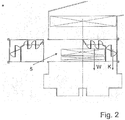
- two modules 4, 4 ' are provided for each climate zone, wherein the modules 4, 4' can be pushed in and pulled out from different sides or even the same side. If, for example, the heater H is to be exchanged with the heater h, then one of the modules 4, 4 'is released, pulled out ( Fig. 2 ) and then the heater H can be removed with the heater h and replaced ( Figure 3 ). Subsequently, the module 4, 4 'is inserted again and attached.
- Fig. 4 shows a sectional view taken along the plane AA of Fig. 1 , The valve assembly located between heater H and evaporator V or the flaps 3 are in Fig. 4 not shown.
- the heater H and auxiliary heater h are integrated directly in a over the entire width of the air guide housing 1 going module 4, which also includes the temperature mixing valves 3.
- the module 4 also forms an insertion part, which is inserted into a correspondingly formed insert 5 from the side of the air guide housing 1.
- an arrangement of an evaporator in a comparable module is possible. Due to the variations in the number of zones, which is associated with partitions in the range of heater and heater and in particular affects the number of temperature mixing valves and / or a coupling of the same, but the modular structure is particularly advantageous in the range of heater / heater ,
- FIGS. 7 and 8 is a third embodiment of a four-zone air conditioning with heater H, in the present case without heater, but such may well be provided, shown.
- This heater H together with the upper and lower temperature mixing flaps 3 for each side of the module 4, which is inserted into a shaft-like slot 5 and as a unit between the top and bottom arranged cold air ducts in the air duct housing and can be removed.
- the evaporator V is arranged, which is not explicitly shown.
- the temperature mixing valves 3 of the third embodiment are combined swing-slide valves.
- a three-zone air conditioning system which has three temperature mixing flaps, namely two upper and one lower temperature mixing flap.
- a two-zone air conditioning system which according to a first embodiment, two temperature mixing flaps, one for each side, which are each pointed below, and according to a second embodiment, four temperature mixing flaps, which are coupled together.
- a temperature mixing flap is provided above.
- the lower openings are closed.
- a temperature mixing flap may also be provided below, which is coupled to the upper, for example.
- module 4 which is constructed in two parts. It consists essentially of an outer part 6 and an inner part 7, the two parts 6, 7 are added to the in Fig. 9c shown module or insert 4 assembled.
- a multi-part design is advantageous.
- a temperature mixing flap in the left module 4 and in the right module 4 ' is provided, which in the Figures 9 but not shown.
- the outer wall regions 9 of the modules 4 and 4 ' form the wall of the air-guiding housing 1 of the air-conditioning system.
- circumferential sealing areas such as sealing lips, sealing rings, and / or a groove or spring, which can be brought into engagement with the corresponding counterpart of the air guide housing, provided.
- the mounting part is screwed to the air guide housing, for which purpose 10 screw dome 24 are formed on the mounting part.
- a heater H and optionally a heater h
- a receptacle 8 in the bottom region of the modules 4, 4 ' is provided.
- a simple replacement of the heater H and / or auxiliary heater h is made possible by an insertion opening in the upper region of the modules 4, 4 ', but the removal of the heater H and / or auxiliary heater h can also be done by removing one or both modules 4, 4' ,
- a module according to the invention following module 4, 4 'made of three or more parts composed.
- a module or insert 4 is in the FIGS. 10a to 10c shown.
- the module 4 is formed from an upper part 15, a lower part 14 and a frame part 16.
- the three parts are again sealingly connectable, in particular screwed, verclips - and / or welded.
- substantially mirror image formed module 4 creates a built-in part 10, which in turn receives a heater H and / or a heater h and serves as an air handling and Heiltemperierech.
- an intermediate bottom 17 is provided which can be integrated as a separate part in the arrangement or connectable to this or is part of the upper part 15 or the lower part 14.
- the false floor divides the arrangement in upper and lower air ducts according to the formation of zones for further air conditioning of the interior.
- FIG. 13 Another embodiment of a three-part design of a module 4, present in an upper part 15, a lower part 14 and an intermediate bottom 17 is in Fig. 13 shown.
- the intermediate bottom has a web 22 on which is in the assembled state by means of its ends in engagement with the upper part 15 and the lower part 14.
- a built-in part 10 is shown with a corresponding flap arrangement for temperature control of the passing air.
- a module 4 with a substantially mirror-image module 4 ' is connected to one another at the vertical parting line 18.
- the modules 4, 4 ' can be made in two parts or in three parts and connected to one another at a horizontal parting line 19.
- a pivot slide door 3 is arranged, which is mounted on a pivot axis 21 and a pin which engages in a slot-like guide 12, pivotally and slidably in the mounting part 10.
- the arrangement of the flaps 3 is mirror-inverted with respect to the median plane in the region of the vertical parting line 18th
- the air path through the radiator H is closed and only the lateral cold air ducts K are open.
- the pivoting sliding flaps 3 can be moved to the inside of the outer wall 9 of the modules and thereby close the cold air ducts and release the path of the air through the radiator H, h.
- intermediate positions of the flap 3 is obtained behind the built-in part 10 mixed air from cold and warm air, which then according to the zones of the air conditioner, this are two, the vehicle interior can be supplied.
- the in Fig. 12 shown arrangement, an intermediate bottom 17 in the horizontal separation area 19.
- the modules 4, 4 'thus each consist of an upper part 15, a lower part 14 and the intermediate floor or moteinlegeteil 17.
- the upper flaps 3 for controlling the air mass flow in the front of a Vehicle in their surface slightly larger than the lower flaps 3 are designed for controlling the temperature of the air mass flow in the rear space of a vehicle.
- a mechanical flap coupling which connects, for example, the two lower flaps 3 for the rear compartment, so that they are controllable via a common control device.
- the coupling is outside the air duct housing 1, so that at least the interior of the air conditioner for the three-and four-zone variant are identical.
- a two- or even mono-air conditioning with correspondingly simplified control can be made, so that very large quantities are possible at least for parts of the air duct housing and the built-in part, whereby the production costs can be reduced.
- the front and the rear area or the right side and the left side can be coupled with each other.
- the in the FIGS. 11 and 12 shown built-in parts 10 can be connected in their entirety with the air duct housing the air conditioning.
- Fig. 14 shows a section through a fitting 10 after 11 or 12 in the state installed in an air conditioner.
- the openings of the cold air ducts K and the hot air ducts W, are controlled by the flaps 3 by means of a pivot-sliding movement.
- the built-in part 10 is integrated as a complete insert part in the air guide housing 1 of the air conditioner, wherein the walls 9 of the modules 4, 4 'form part of the air guide housing 1, which is broken at the installation point.
- the Heilverteilhow connects which is designed with air outlets or air ducts 23 and any air flow control means such as flaps and the task, the tempered by means of the flaps 3 and the heat exchanger V, H, h air to supply the individual Heilausström Suiteen in the vehicle interior such as ventilation, defrost or expediauslässen in the front and / or rear area.
Landscapes
- Physics & Mathematics (AREA)
- Thermal Sciences (AREA)
- Engineering & Computer Science (AREA)
- Mechanical Engineering (AREA)
- Air-Conditioning For Vehicles (AREA)
- Sorption Type Refrigeration Machines (AREA)
Description
- Die Erfindung betrifft eine Klimaanlage, insbesondere Kraftfahrzeug-Klimaanlage, gemäß dem Oberbegriff des Anspruches 1.
- Bei herkömmlichen Klimaanlagen erfolgt für jede Änderung eine neue Auslegung derselben, insbesondere des Luftführungsgehäuses mit den darin angeordneten Luftführungskanälen bis hin zum Verdampfer, Heizer und gegebenenfalls Zuheizer. So ergibt sich, dass für jede Variante die gesamte Klimaanlage neu konstruiert werden muss und für jede Variante spezielle Werkzeuge erforderlich sind.
- Die
EP 1 288 031 A1 offenbart eine modular aufgebaute Kraftfahrzeug-Klimaanlage mit Mitteln zur Verteilung eines Haupt-Luftstroms, einem Verdampfer und einem Heizer zum Erwärmen eines zweiten Luftstroms. Die Klimaanlage ist in einem Gehäuse angeordnet. Den modularen Aufbau der Klimaanlage gibt es in wenigstens drei Versionen, nämlich für eine ein-, eine zwei- und eine dreizonige Klimaanlage, die für die Erzeugung eines Luftstroms mit vorgegebener Temperatur in den entsprechenden Zonen geeignet ist. Hierbei ist der äußere Aufbau der verschiedenen Versionen der Klimaanlage identisch, unabhängig von der Zonenanzahl. Der modulare Aufbau wird im Wesentlichen durch eine Vielzahl unterschiedlicher Einlegeteile gebildet, welche das Gehäuse entsprechend der gewünschten Zonenanzahl unterteilen. Hierbei werden, jeweils der gewünschten Zonenanzahl entsprechend, Einlegeteile in das Luftführungsgehäuse eingebaut. Eine derartigere Klimaanlage lässt noch Wünsche offen. - Die
WO 2004/000589 A1 offenbart eine Klimaanlage gemäß dem Oberbegriff von Anspruch 1. - Es ist Aufgabe der Erfindung, eine verbesserte Klimaanlage zur Verfügung zu stellen.
- Diese Aufgabe wird gelöst durch eine Klimaanlage mit den Merkmalen des Anspruchs 1. Vorteilhafte Ausgestaltungen sind Gegenstand der Unteransprüche.
- Erfindungsgemäß ist eine Klimaanlage, insbesondere Kraftfahrzeug-Klimaanlage, vorgesehen, mit einem mehrteilig ausgebildeten Luftführungsgehäuse und in demselben angeordneten Komponenten, wie mindestens einem Heizer, wobei das Luftführungsgehäuse im Bereich mindestens einer Komponente als Einsatzteil oder Modul ausgebildet ist. Erfindungsgemäß ist der Heizer im Einsatzteil angeordnet. Bevorzugt ist ein Zuheizer in einem Einsatz angeordnet oder Teil des Einsatzes, der im Luftführungsgehäuse angeordnet ist. Dies ermöglicht eine bedarfsgerechte, das heißt unter anderem eine an die Klimazonenanzahl angepasste, Ausbildung der Kanäle und diesen zugeordneter Klappen, wie insbesondere Temperaturmischklappen. Ferner ermöglicht die Anordnung im Einsatz die breitere Verwendung des Luftführungsgehäuses, da spezielle Ausgestaltungen, beispielsweise für ein-und zweizonige und drei- und vierzonige Klimaanlagen, am Einsatz vorgenommen werden können, wie beispielsweise die Anordnung von Temperaturmischklappen und/oder gegebenenfalls auch das Vorsehen von Abdeckungen von beispielsweise im ein- und zweizonigen Anwendungsfall nicht benötigten Kanälen.
- Erfindungsgemäß erfolgt die Ausgestaltung des Einsatzteils als Einschubteil, welches auf einfache Weise von der Seite des Luftführungsgehäuses her in einen im Luftführungsgehäuse ausgebildeten, schachtartigen Einschub eingeschoben werden kann.
- Der Einschub ist bevorzugt zwischen zwei oben und unten und/oder seitlich angeordneten Kaltluftkanälen angeordnet, so dass das Luftführungsgehäuse ausreichend stabil ausgebildet und der Einschub durch einen Schacht gebildet ist.
- Vorteilhafterweise sind die in der Klimaanlage ausgebildeten Warmluftkanäle Teil des Einsatzteils, bzw. werden von den Wandungen des Einsatzteils begrenzt. Ein Kaltluftkanal ist entweder im Luftführungsgehäuse angeordnet oder ebenfalls Teil des Einsatzteils.
- Vorzugsweise ist das Einsatzteil mehrteilig, insbesondere zwei-, drei-, oder vierteilig ausgebildet.
- Bevorzugt sind die Klimaanlagen für im Bereich des Luftführungsgehäuses für unterschiedliche Zonenanzahlen im Wesentlichen gleich ausgebildet, wobei hierbei beispielsweise zonenspezifische Einlegeteile, Trennwände und/oder Abdeckungen vorgesehen sein können, und sich die einzelnen Klimaanlagen in Hinblick auf die unterschiedliche Zonenanzahl durch das Einsatzteil unterscheiden. Dies ermöglicht eine vereinfachte Konstruktion der verschiedenzonigen Klimaanlagen. Ferner lassen sich Klimaanlagen relativ einfach umbauen. Hauptvorteil ist jedoch die verbesserte Servicefreundlichkeit in Hinblick auf eine Reparatur oder einen Austausch des Heizers und/oder Zuheizers.
- Vorzugsweise sind zwei Einsatzteile oder Module, insbesondere Einschubteile, vorgesehen, welche bevorzugt von unterschiedlichen Seiten des Luftführungsgehäuses her eingebaut werden können. Die Teilung, insbesondere eine mittige Teilung, vereinfacht die Herstellung und Montage. Ferner kann eine Reparatur durch das Entfernen nur eines Einsatzteils erfolgen.
- Vorteilhaft ist, dass die Klimaanlage zumindest eines der folgenden Bauteile umfasst: Verdampfer, Filter, Mischkammer, eine oder mehrere Steuerklappen zur Verteilung der Luft auf die Luftauslässe.
- Im Folgenden wird die Erfindung anhand mehrerer Ausführungsbeispiele mit Varianten, teilweise unter Bezugnahme auf die Zeichnung, im Einzelnen erläutert. In der Zeichnung zeigen:
- Fig. 1
- eine schematische Schnittdarstellung einer Kraftfahrzeug-Klimaanlage gemäß dem ersten Ausführungsbeispiel im zusammengebauten Zustand,
- Fig. 2
- einen Teil der Kraftfahrzeug-Klimaanlage von
Fig. 1 mit teilweise ausgebautem Modul, - Fig. 3
- einen Teil der Kraftfahrzeug-Klimaanlage von
Fig. 1 mit ausgebautem Heizer und Zuheizer, - Fig. 4
- eine Schnittdarstellung des ersten Ausführungsbeispiels aus einer anderen Perspektive,
- Fig. 5
- eine schematische Schnittdarstellung einer Kraftfahrzeug-Klimaanlage gemäß dem zweiten Ausführungsbeispiel im zusammengebauten Zustand,
- Fig. 6
- einen Teil der Kraftfahrzeug-Klimaanlage von
Fig. 5 mit ausgebautem Modul, - Fig. 7
- eine schematische Schnittdarstellung einer Kraftfahrzeug-Klimaanlage gemäß dem dritten Ausführungsbeispiel im zusammengebauten Zustand, und
- Fig. 8
- eine perspektivische Darstellung des dritten Ausführungsbeispiels mit ausgebautem Modul samt Heizer, und
- Fig. 9a - 9d
- eine perspektivische Darstellung des vierten Ausführungsbeispiels eines Einbauteils, sowie Einzelteile desselben, ohne Heizer und Klappen, und
- Fig. 10a - 10c
- eine perspektivische Darstellung des fünften Ausführungsbeispiels eines Teils eines Einbauteils, sowie Einzelteile desselben ohne Heizer und Klappen, und
- Fig. 11
- eine schematische perspektivische Darstellung des vierten Ausführungsbeispiels eines Einbauteils mit eingebauten Klappen, und
- Fig. 12
- eine schematische perspektivische Darstellung des fünften Ausführungsbeispiels eines Einbauteils mit eingebauten Klappen, und
- Fig. 13
- eine schematische perspektivische Darstellung des sechsten Ausführungsbeispiels eines Moduls ohne Heizer und Klappen, und
- Fig. 14
- eine schematische Schnittdarstellung durch das vierte oder fünfte Ausführungsbeispiel eines Einbauteils im eingebauten Zustand.
- Eine vorliegend, wie in
Fig. 1 dargestellt, zweizonig ausgebildete Kraftfahrzeug-Klimaanlage weist ein Luftführungsgehäuse 1 mit in demselben angeordnetem Heizer H, Zuheizer h und Verdampfer V auf, wobei das Luftführungsgehäuse 1 aus fertigungs- und montagetechnischen Gründen mehrteilig als Kunststoff-Spritzgussteil ausgebildet ist. Stromaufwärts des Verdampfers V ist ein Filter F und ein Gebläse G (nicht näher dargestellt) zur Förderung der zu klimatisierenden Luft angeordnet. In dem Luftführungsgehäuse 1 sind eine Mehrzahl von Luftkanälen 2 und Klappen 3 (vorliegend sind nur Temperaturmischklappen dargestellt) zur Steuerung der Luftströmung mit Hilfe von Einlegeteilen (nicht näher dargestellt) ausgebildet bzw. ungeordnet. So sind zwei mittig angeordnete Warmluftkanäle W, durch welche die vom Verdampfer V kommende Luft durch den Heizer H und Zuheizer h geführt und hierin erwärmt wird, und je ein oben und unten angeordneter Kaltluftkanal K, welche die vom Verdampfer V kommende Luft am Heizer H und Zuheizer h vorbeiführen, vorgesehen. Die Lufttemperierung und/oder Luftverteilung erfolgt mit Hilfe der Temperaturmischklappen. Anstelle der schematisch dargestellten zweiflügligen Klappen, können selbstverständlich auch einflügelige Klappen, Schiebeklappen, Rollbandkassetten, Lamellenklappen und ähnliche Klappenanordnungen Verwendung finden. - Der Heizer H und der Zuheizer h, welcher durch PTC-Elemente gebildet ist, sind mitsamt der Temperaturmischklappen in zwei Modulen 4, 4' angeordnet, welche beispielsweise mit den Außenwandungen 9 auch einen Teil des mehrteiligen Luftführungsgehäuses 1 bilden. Jedes Modul 4, 4' ist als Einsatzteil, vorliegend als ein Einschubteil, ausgebildet, welches in einen vom Hauptteil des Luftführungsgehäuses 1 gebildeten schachtartigen Einschub 5 von der Seite eingeschoben werden kann, wofür die Kanten des Hauptteils des Luftführungsgehäuses 1 und des Moduls 4 entsprechende Führungen und Abdichtungen aufweisen. Die Module 4, 4' sind derart mit dem Luftführungsgehäuse 1 verbunden, dass der Strömungsverlauf der Luft geringstmöglich negativ beeinflusst wird, wofür die Innenwand des Luftführungsgehäuses 1 im Wesentlichen stetig in die Wandung der Module übergeht, so dass möglichst keine Kanten im Bereich der Übergänge in den Luftströmungsweg hineinragen.
- Eine etwa spiegelbildliche Ausbildung einzelner Module ist in den Bezugszeichen mit einem gestrichenen Index angedeutet. Im Folgenden wird der Einfachheit halber für die weiteren Bauteile darauf verzichtet.
- Gemäß dem ersten Ausführungsbeispiel sind zwei Module 4, 4', für jede Klimazone eines, vorgesehen, wobei die Module 4, 4' von unterschiedlichen Seiten oder auch derselben Seite eingeschoben und herausgezogen werden können. Soll beispielsweise der Heizer H mit dem Zuheizer h ausgetauscht werden, so wird eines der Module 4, 4' gelöst, herausgezogen (
Fig. 2 ) und anschließend kann der Heizer H mit dem Zuheizer h entnommen und ersetzt werden (Fig.3 ). Anschließend wird das Modul 4, 4' wieder eingeschoben und befestigt.Fig. 4 zeigt eine Schnittdarstellung entlang der Ebene A-A vonFig. 1 . Die sich zwischen Heizer H und Verdampfer V befindliche Klappenanordnung bzw. die Klappen 3 sind inFig. 4 nicht dargestellt. - Gemäß dem zweiten, in den
Figuren 5 und 6 dargestellten Ausführungsbeispiel sind der Heizer H und Zuheizer h direkt in einem über die gesamte Breite des Luftführungsgehäuses 1 gehenden Modul 4 integriert, welches ebenfalls die Temperaturmischklappen 3 umfasst. Das Modul 4 bildet ebenfalls ein Einschubteil, welches in einen entsprechend ausgebildeten Einschub 5 von der Seite des Luftführungsgehäuses 1 eingeschoben wird. - Ebenfalls ist gemäß einer Variante eine Anordnung eines Verdampfers in einem vergleichbaren Modul möglich. Auf Grund der Variationsmöglichkeiten in Hinblick auf die Zonenanzahl, die verbunden mit Trennwänden im Bereich von Heizer und Zuheizer ist und insbesondere Auswirkungen auf die Anzahl der Temperaturmischklappen und/oder eine Koppelung derselben hat, ist der modulare Aufbau aber besonders im Bereich von Heizer/Zuheizer vorteilhaft.
- In den
Figuren 7 und 8 ist ein drittes Ausführungsbeispiel einer vierzonigen Klimaanlage mit Heizer H, vorliegend ohne Zuheizer, jedoch kann ein solcher durchaus auch vorgesehen sein, dargestellt. Dieser Heizer H ist samt den oberen und unteren Temperaturmischklappen 3 für jede Seite Teil des Moduls 4, welches in einen schachtartigen Einschub 5 eingeführt ist und als eine Einheit zwischen den oben und unten angeordneten Kaltluftkanälen in das Luftführungsgehäuse ein- und ausgebaut werden kann. Im linken Teil vonFig. 7 und im rechten Teil vonFig. 8 ist der Verdampfer V angeordnet, welcher nicht explizit dargestellt ist. Bei den Temperaturmischklappen 3 des dritten Ausführungsbeispiels handelt es sich um kombinierte Schwenk-Schiebeklappen. - Gemäß einer nicht in der Zeichnung dargestellten Variante des dritten Ausführungsbeispiels ist eine dreizonige Klimaanlage vorgesehen, welche drei Temperaturmischklappen aufweist, nämlich zwei obere und eine untere Temperaturmischklappe.
- Entsprechend zweier weiterer Varianten des dritten Ausführungsbeispiels ist eine zweizonige Klimaanlage vorgesehen, welche gemäß einer ersten Ausführungsform zwei Temperaturmischklappen, nämlich für jede Seite eine, die unten jeweils zugespitzt sind, und gemäß einer zweiten Ausführungsform vier Temperaturmischklappen aufweist, welche miteinander gekoppelt sind.
- In einer letzten Variante für eine einzonige Klimaanlage ist - unter Verwendung des gleichen Luftführungsgehäuses - lediglich eine Temperaturmischklappe oben vorgesehen. Die unteren Öffnungen sind verschlossen. Alternativ kann unten ebenfalls eine Temperaturmischklappe vorgesehen sein, die beispielsweise mit der oberen gekoppelt ist.
- In den
Figuren 9a bis 9d ist ein weiteres der Erfindung folgendes Modul 4 dargestellt. welches zweiteilig aufgebaut ist. Es besteht im Wesentlichen aus einem Außenteil 6 und einem Innenteil 7, Die beiden Teile 6, 7 werden zu dem inFig. 9c dargestellten Modul oder Einsatzteil 4 zusammengefügt. Insbesondere bei der Herstellung dieses Moduls 4 mittels Kunststoffgießens bzw. Kunststoffspritzgießens ist eine mehrteilige Ausführung vorteilhaft. Durch Zusammenfügen, beispielsweise Schweißen, Schrauben, Clipsen oder Ähnlichem eines solchen Moduls 4 mit einem im Wesentlichen spiegelbildlich ausgebildeten weiteren Modul 4' entsteht gemäß der Darstellung inFig. 9d ein komplexes direkt in das Luftführungsgehäuse einer Kraftfahrzeug-Klimaanlage integrierbares Einbauteil 10. Im vorliegenden Beispiel ist jeweils eine Temperaturmischklappe im linken Modul 4 und im rechten Modul 4' vorgesehen, die in denFiguren 9 jedoch nicht dargestellt sind. Im unteren sowie im oberen Bereich des Einbauteils sind nutartige Führungen 12, sowie Lagerstellen 11 für die als Temperaturmischklappen eingesetzten kombinierten Schwenk- Schiebeklappen vorgesehen. Im in die Klimaanlage eingebauten Zustand des Einbauteils 10, bilden die Außenwandungsbereiche 9 der Module 4 und 4' die Wandung des Luftführungsgehäuses 1 der Klimaanlage. Für den Anschluß des Einbauteils 10 an das Luftführungsgehäuse sind vorteilhafterweise umlaufende Dichtbereiche, beispielsweise Dichtlippen, Dichtringe, und/oder eine Nut oder Feder, die mit dem entsprechenden Gegenstück des Luftführungsgehäuses in Eingriff gebracht werden können, vorgesehen. Zudem wird das Einbauteil mit dem Luftführungsgehäuse verschraubt, wobei hierfür am Einbauteil 10 Schraubdome 24 ausgebildet sind. Für einen Heizer H, sowie optional einen Zuheizer h ist eine Aufnahme 8 im Bodenbereich der Module 4, 4' vorgesehen. Ein einfacher Austausch des Heizers H und/oder Zuheizers h wird durch eine Einfuhröffnung im oberen Bereich der Module 4, 4' ermöglicht, jedoch kann der Ausbau des Heizers H und/oder Zuheizers h auch durch Entfernen eines oder beider Module 4, 4' erfolgen. - Insbesondere für mehrzonige Klimaanlagen und die dafür unter Umständen aufwändigeren Ausführungen der Luftführungsgehäuse, kann es für eine einfache Entformbarkeit vorteilhaft sein, ein dem Erfindungsgedanken folgendes Modul 4, 4' aus drei oder mehr Teilen zusammengesetzt auszuführen. Ein solches Modul bzw. Einsatzteil 4 ist in den
Figuren 10a bis 10c dargestellt. Dabei wird das Modul 4 aus einem Oberteil 15, einem Unterteil 14 und einem Rahmenteil 16 gebildet. Die drei Teile sind untereinander wieder dichtend verbindbar, insbesondere verschraub, verclips - und/oder verschweißbar. Mittels eines nicht dargestellten im Wesentlichen spiegelbildlich ausgebildeten Moduls 4' entsteht ein Einbauteil 10, welches wiederum einen Heizer H und/oder einen Zuheizer h aufnimmt und als Luftführungs- und Lufttemperiereinheit dient. Als weiterer Unterschied zum in denFiguren 9 dargestellten Ausführungsbeispiel, ist ein Zwischenboden 17 vorgesehen, der als separates Teil in die Anordnung integrierbar bzw. mit dieser verbindbar ist oder Teil des Oberteils 15 oder des Unterteils 14 ist. Der Zwischenboden teilt die Anordnung in obere und untere Luftführungskanäle entsprechend der Ausbildung von Zonen für die weitere Klimatisierung des Innenraums. - Ein weiteres Ausführungsbeispiel für eine dreiteilige Ausführung eines Moduls 4, vorliegend in ein Oberteil 15, ein Unterteil 14 und einen Zwischenboden 17 ist in
Fig. 13 dargestellt. Der Zwischenboden weist einen Steg 22 auf der sich mittels seiner Enden im zusammengebauten Zustand im Eingriff mit dem Oberteil 15 und dem Unterteil 14 befindet. - In den
Figuren 11 und 12 ist jeweils ein Einbauteil 10 mit einer entsprechenden Klappenanordnung zur Temperierung der hindurchtretenden Luft dargestellt. In dem inFig. 11 gezeigten Einbauteil ist ein Modul 4 mit einem im Wesentlichen spiegelbildlichen Modul 4' an der Vertikaltrennfuge 18 miteinander verbunden. Optional aber nicht notwendigerweise können die Module 4, 4' zweiteilig oder dreiteilig ausgeführt und an einer Horizontaltrennfuge 19 miteinander verbunden sein. In jedem der Module ist eine Schwenk- Schiebeklappe 3 angeordnet, die über eine Schwenkachse 21 und über einen Zapfen, der in eine langlochartige Führung 12 eingreift, schwenk- und verschiebbar im Einbauteil 10 gelagert ist. Die Anordnung der Klappen 3 ist spiegelbildlich bezüglich der Mittelebene im Bereich der vertikalen Trennfuge 18. - Im vorliegenden Beispiel ist der Luftweg durch den Heizkörper H geschlossen und nur die seitlichen Kaltluftkanäle K sind geöffnet. Die Schwenk-Schiebeklappen 3 können bis an die Innenseite der Außenwandung 9 der Module bewegt werden und dabei die Kaltluftkanäle verschließen und den Weg der Luft durch den Heizkörper H, h freigeben. In Zwischenstellungen der Klappe 3 erhält man hinter dem Einbauteil 10 Mischluft aus kalter und warmer Luft, die dann entsprechend den Zonen der Klimaanlage, vorliegend sind dies zwei, dem Fahrzeuginnenraum zugeführt werden können. Durch eine einfache mechanische Kopplung der beiden Klappen, beispielsweise, durch eine außerhalb des Gehäuses angebrachte Koppelvorrichtung, erhält man aus der zweizonigen eine einzonige Klimaanlage.
- In Unterscheidung zu dem in
Fig. 11 dargestellten Ausführungsbeispiel weist die inFig. 12 dargestellte Anordnung, einen Zwischenboden 17 im horizontalen Trennbereich 19 auf. Die Module 4, 4' bestehen somit jeweils aus einem Oberteil 15, einem Unterteil 14 und dem Zwischenboden oder Zwischeneinlegeteil 17. Durch die Ausbildung von vier Klappen 3 ist eine vierzonige Klimaanlage realisierbar, wobei die oberen Klappen 3 zur Temperierung des Luftmassenstroms in den Frontraum eines Fahrzeuges in ihrer Fläche etwas größer als die unteren Klappen 3 zur Temperierung des Luftmassenstroms in den Fondraum eines Fahrzuges ausgeführt sind. - Um bei der Fertigung aus einer vierzonigen Klimaanlage, eine dreizonige Klimaanlage mit vereinfachter Steuerung zu machen, ist eine mechanische Klappenkoppelung vorgesehen, welche beispielsweise die zwei unteren Klappen 3 für den Fondraum verbindet, so dass sie über eine gemeinsame Steuervorrichtung steuerbar sind. Somit sind anstelle von vier Steuervorrichtungen, beispielsweise Elektromotoren nur drei Steuervorrichtungen erforderlich. Vorteilhafterweise erfolgt die Kopplung außerhalb des Luftführungsgehäuses 1, so dass zumindest der Innenraum der Klimaanlage für die drei-und vierzonige Variante identisch ausgebildet sind.
- Prinzipiell kann aus der vierzonigen Klimaanlage durch entsprechende Kopplungen auch eine zwei- oder gar einzonige Klimaanlage mit entsprechend vereinfachter Steuerung gemacht werden, so dass sehr große Stückzahlen zumindest für Teile des Luftführungsgehäuses und das Einbauteil möglich sind, wodurch die Herstellungskosten gesenkt werden können. So lassen sich beispielsweise der Front- und der Fondbereich oder die rechte Seite und die linke Seite jeweils untereinander koppeln. Die in den
Fig. 11 und 12 dargestellten Einbauteile 10 können in Ihrer Gesamt mit dem Luftführungsgehäuse der Klimaanlage verbunden werden. -
Fig. 14 zeigt einen Schnitt durch ein Einbauteil 10 nachFig. 11 oder 12 im in eine Klimaanlage eingebauten Zustand. Die Öffnungen der Kaltluftkanäle K und der Warmluftkanäle W, werden durch die Klappen 3 mittels einer Schwenk- Schiebebewegung gesteuert. Das Einbauteil 10 ist als komplettes Einsatzteil in das Luftführungsgehäuse 1 der Klimaanlage integriert, wobei die Wandungen 9 der Module 4, 4' einen Teil des Luftführungsgehäuses 1 bilden, welches an der Einbaustelle durchbrochen ist. Im Bereich nach dem Einbauteil 10, schließt sich die Luftverteileinheit an, die mit Luftauslässen bzw. Luftkanälen 23 und eventuellen Luftstromsteuermitteln wie beispielsweise Klappen ausgeführt ist und die, die Aufgabe hat, die mittels der Klappen 3 und der Wärmetauscher V, H, h temperierte Luft den einzelnen Luftausströmbereichen im Fahrzeuginnenraum wie Belüftung-, Defrost- oder Fußraumauslässen im Front und/oder Heckbereich zuzuführen.
Claims (8)
- Klimaanlage, insbesondere Kraftfahrzeug-Klimaanlage, mit einem mehrteilig ausgebildeten Luftführungsgehäuse (1) und in demselben angeordneten Komponenten, wie mindestens einem Heizer (H; h), wobei das Luftführungsgehäuse (1) im Bereich mindestens einer Komponente als Einsatzteil in Form eines Moduls (4) ausgebildet ist, wobei das Einsatzteil ein Einschubteil ist, und das Luftführungsgehäuse (1) im Bereich der Komponente als Einschub (5) ausgebildet ist, im Einsatzteil Temperaturmischklappen (3) angeordnet sind und die Temperaturmischklappen (3) fest in das Einsatzteil integriert sind und einen Teil desselben bilden, wobei die Klimaanlage für im Bereich des Luftführungsgehäuses (1) für unterschiedliche Zonenanzahlen im Wesentlichen gleich ausgebildet ist und sich durch das Einsatzteil unterscheiden, wobei die Klimaanlage eine mehrzonige Klimaanlage ist, die mindestens ein Einlegeteil aufweist, welche die Luftkanäle der einzelnen Zonen voneinander trennt, wobei das Einsatzteil als Einschubteil ausgebildet ist, welches von der Seite des Luftführungsgehäuses her in einen im Luftführungsgehäuse ausgebildeten schachtartigen Einschub einschiebbar ist, dadurch gekennzeichnet, dass im Einsatzteil der Heizer (H; h) angeordnet ist.
- Klimaanlage nach Anspruch 1, dadurch gekennzeichnet, dass der Heizer (H; h) fest in das Einsatzteil integriert ist und einen Teil desselben bildet.
- Klimaanlage nach einem der vorhergehenden Ansprüche, dadurch gekennzeichnet, dass zwei Einsatzteile vorgesehen sind.
- Klimaanlage nach Anspruch 3, dadurch gekennzeichnet, dass die Einsatzteile einen im Wesentlichen spiegelbildlichen Aufbau haben.
- Klimaanlage nach einem der vorhergehenden Ansprüche, dadurch gekennzeichnet, dass ein oder mehrere Warmluftkanäle (W) mittig und ein oder mehrere Kaltluftkanäle (K) seitlich und/oder oben und/oder unten bezüglich der Warmluftkanäle (W) ausgebildet sind.
- Klimaanlage nach Anspruch 5, dadurch gekennzeichnet, dass der Warmluftkanal (W) Teil des Einsatzteils ist.
- Klimaanlage nach Anspruch 5 oder 6, dadurch gekennzeichnet, dass der Kaltluftkanal (K) Teil des Einsatzteils ist.
- Klimaanlage nach einem der vorhergehenden Ansprüche, dadurch gekennzeichnet, dass das Einsatzteil mehrteilig ausgebildet ist.
Applications Claiming Priority (2)
| Application Number | Priority Date | Filing Date | Title |
|---|---|---|---|
| DE102004030697 | 2004-06-24 | ||
| EP05772777A EP1761406B1 (de) | 2004-06-24 | 2005-06-24 | Klimaanlage, insbesondere kraftfahrzeug-klimaanlage |
Related Parent Applications (2)
| Application Number | Title | Priority Date | Filing Date |
|---|---|---|---|
| EP05772777A Division EP1761406B1 (de) | 2004-06-24 | 2005-06-24 | Klimaanlage, insbesondere kraftfahrzeug-klimaanlage |
| EP05772777.8 Division | 2005-06-24 |
Publications (2)
| Publication Number | Publication Date |
|---|---|
| EP2272697A1 EP2272697A1 (de) | 2011-01-12 |
| EP2272697B1 true EP2272697B1 (de) | 2018-03-21 |
Family
ID=35079350
Family Applications (2)
| Application Number | Title | Priority Date | Filing Date |
|---|---|---|---|
| EP10183686.4A Expired - Lifetime EP2272697B1 (de) | 2004-06-24 | 2005-06-24 | Klimaanlage, insbesondere Kraftfahrzeug-Klimaanlage |
| EP05772777A Expired - Lifetime EP1761406B1 (de) | 2004-06-24 | 2005-06-24 | Klimaanlage, insbesondere kraftfahrzeug-klimaanlage |
Family Applications After (1)
| Application Number | Title | Priority Date | Filing Date |
|---|---|---|---|
| EP05772777A Expired - Lifetime EP1761406B1 (de) | 2004-06-24 | 2005-06-24 | Klimaanlage, insbesondere kraftfahrzeug-klimaanlage |
Country Status (5)
| Country | Link |
|---|---|
| US (1) | US8474513B2 (de) |
| EP (2) | EP2272697B1 (de) |
| AT (1) | ATE487624T1 (de) |
| DE (1) | DE502005010514D1 (de) |
| WO (1) | WO2006000433A1 (de) |
Families Citing this family (16)
| Publication number | Priority date | Publication date | Assignee | Title |
|---|---|---|---|---|
| DE102007041689A1 (de) * | 2007-09-03 | 2009-03-05 | Behr Gmbh & Co. Kg | Klimaanlage für ein Kraftfahrzeug mit einer Fondraumklappe zum Mischen und Verteilen der Luft |
| US8997838B2 (en) * | 2009-07-10 | 2015-04-07 | Keihin Corporation | Vehicular air conditioning apparatus |
| EP2407327B1 (de) * | 2010-07-16 | 2013-12-25 | Eberspächer catem GmbH & Co. KG | Elektrische Heizvorrichtung, insbesondere Kfz-Zusatzheizung sowie Kfz-Klimagerät |
| DE102011051349B4 (de) * | 2011-06-27 | 2022-06-02 | Audi Ag | Wärmeübertragereinheit für Klimageräte in Kraftfahrzeugen |
| DE102012012654A1 (de) | 2012-06-25 | 2014-01-02 | Valeo Klimasysteme Gmbh | Fahrzeugheizungs-, -lüftungs- und/oder -klimaanlage |
| JP6357321B2 (ja) * | 2014-02-26 | 2018-07-11 | サンデンホールディングス株式会社 | 自動車用空調装置 |
| JP6357322B2 (ja) * | 2014-02-26 | 2018-07-11 | サンデンホールディングス株式会社 | 自動車用空調装置 |
| EP3623186A4 (de) * | 2017-05-12 | 2021-03-03 | Valeo Japan Co., Ltd. | Fahrzeugklimaanlage und darauf aufgebrachter rahmenkörper |
| JP2018203217A (ja) * | 2017-06-09 | 2018-12-27 | 株式会社ヴァレオジャパン | 車両用空調装置及びそれに適用される枠体 |
| FR3072613B1 (fr) * | 2017-10-24 | 2020-02-07 | Valeo Systemes Thermiques | Dispositif de chauffage, notamment pour boitier de climatisation d'un vehicule automobile |
| CN111002787B (zh) * | 2018-10-08 | 2023-04-11 | 翰昂汽车零部件有限公司 | 带贯通孔的部件及具备该部件的车辆用空调装置 |
| FR3091577A1 (fr) * | 2019-01-03 | 2020-07-10 | Valeo Systemes Thermiques | Dispositif de chauffage, ventilation et/ou climatisation et installation de chauffage, ventilation et/ou climatisation comportant un tel dispositif |
| DE102019125649B4 (de) * | 2019-09-24 | 2025-07-03 | Audi Ag | Verfahren zum Klimatisieren und Klimavorrichtung |
| FR3111419B1 (fr) * | 2020-06-16 | 2022-06-03 | Valeo Systemes Thermiques | Module d’échange de chaleur comprenant au moins deux échangeurs de chaleur |
| FR3115732B1 (fr) * | 2020-11-04 | 2022-10-14 | Valeo Systemes Thermiques | Module de refroidissement pour véhicule automobile électrique ou hybride à turbomachine tangentielle avec échangeur thermique supplémentaire |
| KR102929651B1 (ko) * | 2021-07-01 | 2026-02-20 | 현대자동차주식회사 | 전기차량용 공조장치 및 이를 이용한 전기차량용 공조시스템 |
Family Cites Families (18)
| Publication number | Priority date | Publication date | Assignee | Title |
|---|---|---|---|---|
| DE3606591A1 (de) * | 1986-02-28 | 1987-09-10 | Bayerische Motoren Werke Ag | Heiz- und kuehlvorrichtung fuer kraftfahrzeuge |
| US4848450A (en) * | 1988-02-09 | 1989-07-18 | C & J Jones (1985) Limited | Heat exchanger |
| GB2217440A (en) * | 1988-04-13 | 1989-10-25 | Ford Motor Co | A heater box |
| DE3916816A1 (de) | 1988-10-28 | 1990-05-03 | Piemontese Radiatori | Vorrichtung fuer die befestigung eines heizkoerpers einer heizeinrichtung fuer den fahrgastraum eines kraftfahrzeugs an einer einen einschubsitz aufweisenden halterung |
| FR2724873A1 (fr) * | 1994-09-23 | 1996-03-29 | Socori Technologies | Procede de realisation d'une unite de chauffage pour climatiseur de vehicules automobiles, moyens en vue de sa mise en oeuvre, unite de chauffage et climatiseur obtenus a l'aide de ce procede. |
| JPH10264639A (ja) | 1997-03-25 | 1998-10-06 | Sanden Corp | 空調装置 |
| JP2000247135A (ja) * | 1999-03-02 | 2000-09-12 | Sanden Corp | 車両用空調装置 |
| US6609563B1 (en) * | 1999-04-13 | 2003-08-26 | Calsonic Kansei Corporation | Vehicular air conditioning apparatus including a detachably installed mix door assembly |
| US6536474B2 (en) * | 2000-03-13 | 2003-03-25 | Calsonic Kansei Corporation | Air conditioner unit for vehicle |
| DE10012972C1 (de) | 2000-03-16 | 2001-03-08 | Daimler Chrysler Ag | Belüftungsvorrichtung für Fahrzeuge |
| JP3851497B2 (ja) * | 2000-09-20 | 2006-11-29 | 株式会社ケーヒン | エアミックスダンパユニット |
| JP2002219929A (ja) | 2001-01-23 | 2002-08-06 | Zexel Valeo Climate Control Corp | ヒータユニット |
| FR2829064B1 (fr) | 2001-08-30 | 2005-01-14 | Valeo Climatisation | Dispositif de generation d'un flux d'air a temperature reglee pour l'habitacle d'un vehicule automobile et appareil de chauffage et/ou de climatisation comportant ce dispositif |
| JP2003104035A (ja) | 2001-09-27 | 2003-04-09 | Zexel Valeo Climate Control Corp | 車両用空調装置 |
| DE10225109A1 (de) | 2002-06-05 | 2003-12-18 | Behr Gmbh & Co | Vorrichtung zur Steuerung eines Luftstroms, insbesondere für eine Heizungs- oder Klimaanlage von Kraftfahrzeugen |
| ATE337194T1 (de) | 2002-06-21 | 2006-09-15 | Behr Gmbh & Co | Modulare heizungs- und/oder klimaanlage für ein kraftfahrzeug |
| US6772833B2 (en) | 2002-07-23 | 2004-08-10 | Visteon Global Technologies, Inc. | HVAC system with modular inserts |
| WO2004014676A1 (de) * | 2002-07-29 | 2004-02-19 | Behr Gmbh & Co. Kg | Klimagehäuse |
-
2005
- 2005-06-24 AT AT05772777T patent/ATE487624T1/de active
- 2005-06-24 US US11/630,341 patent/US8474513B2/en not_active Expired - Fee Related
- 2005-06-24 WO PCT/EP2005/006851 patent/WO2006000433A1/de not_active Ceased
- 2005-06-24 DE DE502005010514T patent/DE502005010514D1/de not_active Expired - Lifetime
- 2005-06-24 EP EP10183686.4A patent/EP2272697B1/de not_active Expired - Lifetime
- 2005-06-24 EP EP05772777A patent/EP1761406B1/de not_active Expired - Lifetime
Non-Patent Citations (1)
| Title |
|---|
| None * |
Also Published As
| Publication number | Publication date |
|---|---|
| EP1761406A1 (de) | 2007-03-14 |
| EP1761406B1 (de) | 2010-11-10 |
| ATE487624T1 (de) | 2010-11-15 |
| US8474513B2 (en) | 2013-07-02 |
| EP2272697A1 (de) | 2011-01-12 |
| DE502005010514D1 (de) | 2010-12-23 |
| US20070271953A1 (en) | 2007-11-29 |
| WO2006000433A1 (de) | 2006-01-05 |
Similar Documents
| Publication | Publication Date | Title |
|---|---|---|
| EP1761406B1 (de) | Klimaanlage, insbesondere kraftfahrzeug-klimaanlage | |
| DE60225979T3 (de) | Vorrichtung zur Erzeugung einer temperaturgeregelten Luftströmung für einen Kraftfahrzeugfahrgastraum und Heizungs- und/oder Klimaanlage mit einer solchen Steuerungsvorrichtung | |
| EP1317356B1 (de) | Heiz- und gegebenenfalls klimagerät für nutzfahrzeuge, z.b. omnibusse | |
| DE19739578A1 (de) | Heizungs- oder Klimaanlage für ein Kraftfahrzeug | |
| EP1110769A2 (de) | Heizungs- oder Klimaanlage für ein Kraftfahrzeug | |
| DE102004033402B4 (de) | Modulsystem zum Aufbau einer 1-Zonen-bis 4-Zonen-Klimaanlage für Fahrzeuge | |
| DE102007048331A1 (de) | Klimaanlage für Kraftfahrzeuge | |
| DE19955616C1 (de) | Klimaanlage für Fahrzeuge | |
| EP1306241B2 (de) | Fahrzeugheiz- und Klimaanlage mit kombinierter Luftmisch- und -verteilklappe | |
| EP1526976B2 (de) | Klimagehäuse | |
| EP1634735B2 (de) | Modulare Kraftfahrzeugklimaanlage | |
| DE102005029774A1 (de) | Klimaanlage, insbesondere Kraftfahrzeug-Klimaanlage | |
| EP1641642B1 (de) | Kraftfahrzeug-klimaanlage | |
| DE69704588T2 (de) | Vorrichtung für die Heizung und/oder Lüftung eines Fahrzeuginnenraumes | |
| EP2011675B1 (de) | Klimaanlage | |
| EP2030816A2 (de) | Klimaanlage für ein Kraftfahrzeug mit einer Fondraumklappe zum Mischen und Verteilen der Luft | |
| EP1761405B1 (de) | Klimaanlage, insbesondere kraftfahrzeug-klimaanlage | |
| DE10031534B4 (de) | Innenraumheiz- und/oder Klimaanlage, insbesondere für ein Kraftfahrzeug, mit Querkanal | |
| DE102005029773A1 (de) | Klimaanlage, insbesondere Kraftfahrzeug-Klimaanlage | |
| DE19755698B4 (de) | Heizungs- oder Klimaanlage für ein Kraftfahrzeug | |
| DE10320750B4 (de) | Fahrzeug-Klimaanlage | |
| EP2088011B1 (de) | Gehäuse-Anordnung für eine Fahrzeugklimaanlage | |
| DE19756166B4 (de) | Luftkanal für eine Heizungs- oder Klimaanlage eines Kraftfahrzeuges sowie damit ausgerüstete Heizungs- oder Klimaanlage | |
| EP1792761B1 (de) | Klappenanordnung | |
| DE102011085809A1 (de) | Klimaanlage |
Legal Events
| Date | Code | Title | Description |
|---|---|---|---|
| PUAI | Public reference made under article 153(3) epc to a published international application that has entered the european phase |
Free format text: ORIGINAL CODE: 0009012 |
|
| AC | Divisional application: reference to earlier application |
Ref document number: 1761406 Country of ref document: EP Kind code of ref document: P |
|
| AK | Designated contracting states |
Kind code of ref document: A1 Designated state(s): AT BE BG CH CY CZ DE DK EE ES FI FR GB GR HU IE IS IT LI LT LU MC NL PL PT RO SE SI SK TR |
|
| 17P | Request for examination filed |
Effective date: 20110712 |
|
| 17Q | First examination report despatched |
Effective date: 20140404 |
|
| RAP1 | Party data changed (applicant data changed or rights of an application transferred) |
Owner name: MAHLE BEHR GMBH & CO. KG |
|
| GRAJ | Information related to disapproval of communication of intention to grant by the applicant or resumption of examination proceedings by the epo deleted |
Free format text: ORIGINAL CODE: EPIDOSDIGR1 |
|
| GRAP | Despatch of communication of intention to grant a patent |
Free format text: ORIGINAL CODE: EPIDOSNIGR1 |
|
| GRAP | Despatch of communication of intention to grant a patent |
Free format text: ORIGINAL CODE: EPIDOSNIGR1 |
|
| INTG | Intention to grant announced |
Effective date: 20171102 |
|
| GRAJ | Information related to disapproval of communication of intention to grant by the applicant or resumption of examination proceedings by the epo deleted |
Free format text: ORIGINAL CODE: EPIDOSDIGR1 |
|
| GRAJ | Information related to disapproval of communication of intention to grant by the applicant or resumption of examination proceedings by the epo deleted |
Free format text: ORIGINAL CODE: EPIDOSDIGR1 |
|
| GRAL | Information related to payment of fee for publishing/printing deleted |
Free format text: ORIGINAL CODE: EPIDOSDIGR3 |
|
| GRAP | Despatch of communication of intention to grant a patent |
Free format text: ORIGINAL CODE: EPIDOSNIGR1 |
|
| GRAS | Grant fee paid |
Free format text: ORIGINAL CODE: EPIDOSNIGR3 |
|
| GRAR | Information related to intention to grant a patent recorded |
Free format text: ORIGINAL CODE: EPIDOSNIGR71 |
|
| GRAS | Grant fee paid |
Free format text: ORIGINAL CODE: EPIDOSNIGR3 |
|
| INTC | Intention to grant announced (deleted) | ||
| GRAA | (expected) grant |
Free format text: ORIGINAL CODE: 0009210 |
|
| INTG | Intention to grant announced |
Effective date: 20180206 |
|
| AC | Divisional application: reference to earlier application |
Ref document number: 1761406 Country of ref document: EP Kind code of ref document: P |
|
| AK | Designated contracting states |
Kind code of ref document: B1 Designated state(s): AT BE BG CH CY CZ DE DK EE ES FI FR GB GR HU IE IS IT LI LT LU MC NL PL PT RO SE SI SK TR |
|
| REG | Reference to a national code |
Ref country code: GB Ref legal event code: FG4D Free format text: NOT ENGLISH |
|
| REG | Reference to a national code |
Ref country code: CH Ref legal event code: EP |
|
| REG | Reference to a national code |
Ref country code: AT Ref legal event code: REF Ref document number: 980697 Country of ref document: AT Kind code of ref document: T Effective date: 20180415 |
|
| REG | Reference to a national code |
Ref country code: IE Ref legal event code: FG4D Free format text: LANGUAGE OF EP DOCUMENT: GERMAN |
|
| REG | Reference to a national code |
Ref country code: DE Ref legal event code: R096 Ref document number: 502005015803 Country of ref document: DE |
|
| REG | Reference to a national code |
Ref country code: FR Ref legal event code: PLFP Year of fee payment: 14 |
|
| REG | Reference to a national code |
Ref country code: NL Ref legal event code: MP Effective date: 20180321 |
|
| PG25 | Lapsed in a contracting state [announced via postgrant information from national office to epo] |
Ref country code: LT Free format text: LAPSE BECAUSE OF FAILURE TO SUBMIT A TRANSLATION OF THE DESCRIPTION OR TO PAY THE FEE WITHIN THE PRESCRIBED TIME-LIMIT Effective date: 20180321 Ref country code: FI Free format text: LAPSE BECAUSE OF FAILURE TO SUBMIT A TRANSLATION OF THE DESCRIPTION OR TO PAY THE FEE WITHIN THE PRESCRIBED TIME-LIMIT Effective date: 20180321 Ref country code: CY Free format text: LAPSE BECAUSE OF FAILURE TO SUBMIT A TRANSLATION OF THE DESCRIPTION OR TO PAY THE FEE WITHIN THE PRESCRIBED TIME-LIMIT Effective date: 20180321 |
|
| REG | Reference to a national code |
Ref country code: LT Ref legal event code: MG4D |
|
| PG25 | Lapsed in a contracting state [announced via postgrant information from national office to epo] |
Ref country code: GR Free format text: LAPSE BECAUSE OF FAILURE TO SUBMIT A TRANSLATION OF THE DESCRIPTION OR TO PAY THE FEE WITHIN THE PRESCRIBED TIME-LIMIT Effective date: 20180622 Ref country code: SE Free format text: LAPSE BECAUSE OF FAILURE TO SUBMIT A TRANSLATION OF THE DESCRIPTION OR TO PAY THE FEE WITHIN THE PRESCRIBED TIME-LIMIT Effective date: 20180321 Ref country code: BG Free format text: LAPSE BECAUSE OF FAILURE TO SUBMIT A TRANSLATION OF THE DESCRIPTION OR TO PAY THE FEE WITHIN THE PRESCRIBED TIME-LIMIT Effective date: 20180621 |
|
| PG25 | Lapsed in a contracting state [announced via postgrant information from national office to epo] |
Ref country code: IT Free format text: LAPSE BECAUSE OF FAILURE TO SUBMIT A TRANSLATION OF THE DESCRIPTION OR TO PAY THE FEE WITHIN THE PRESCRIBED TIME-LIMIT Effective date: 20180321 Ref country code: PL Free format text: LAPSE BECAUSE OF FAILURE TO SUBMIT A TRANSLATION OF THE DESCRIPTION OR TO PAY THE FEE WITHIN THE PRESCRIBED TIME-LIMIT Effective date: 20180321 Ref country code: EE Free format text: LAPSE BECAUSE OF FAILURE TO SUBMIT A TRANSLATION OF THE DESCRIPTION OR TO PAY THE FEE WITHIN THE PRESCRIBED TIME-LIMIT Effective date: 20180321 Ref country code: ES Free format text: LAPSE BECAUSE OF FAILURE TO SUBMIT A TRANSLATION OF THE DESCRIPTION OR TO PAY THE FEE WITHIN THE PRESCRIBED TIME-LIMIT Effective date: 20180321 Ref country code: NL Free format text: LAPSE BECAUSE OF FAILURE TO SUBMIT A TRANSLATION OF THE DESCRIPTION OR TO PAY THE FEE WITHIN THE PRESCRIBED TIME-LIMIT Effective date: 20180321 Ref country code: RO Free format text: LAPSE BECAUSE OF FAILURE TO SUBMIT A TRANSLATION OF THE DESCRIPTION OR TO PAY THE FEE WITHIN THE PRESCRIBED TIME-LIMIT Effective date: 20180321 |
|
| PG25 | Lapsed in a contracting state [announced via postgrant information from national office to epo] |
Ref country code: CZ Free format text: LAPSE BECAUSE OF FAILURE TO SUBMIT A TRANSLATION OF THE DESCRIPTION OR TO PAY THE FEE WITHIN THE PRESCRIBED TIME-LIMIT Effective date: 20180321 Ref country code: SK Free format text: LAPSE BECAUSE OF FAILURE TO SUBMIT A TRANSLATION OF THE DESCRIPTION OR TO PAY THE FEE WITHIN THE PRESCRIBED TIME-LIMIT Effective date: 20180321 |
|
| PG25 | Lapsed in a contracting state [announced via postgrant information from national office to epo] |
Ref country code: PT Free format text: LAPSE BECAUSE OF FAILURE TO SUBMIT A TRANSLATION OF THE DESCRIPTION OR TO PAY THE FEE WITHIN THE PRESCRIBED TIME-LIMIT Effective date: 20180723 |
|
| REG | Reference to a national code |
Ref country code: DE Ref legal event code: R097 Ref document number: 502005015803 Country of ref document: DE |
|
| PLBE | No opposition filed within time limit |
Free format text: ORIGINAL CODE: 0009261 |
|
| STAA | Information on the status of an ep patent application or granted ep patent |
Free format text: STATUS: NO OPPOSITION FILED WITHIN TIME LIMIT |
|
| PG25 | Lapsed in a contracting state [announced via postgrant information from national office to epo] |
Ref country code: DK Free format text: LAPSE BECAUSE OF FAILURE TO SUBMIT A TRANSLATION OF THE DESCRIPTION OR TO PAY THE FEE WITHIN THE PRESCRIBED TIME-LIMIT Effective date: 20180321 |
|
| REG | Reference to a national code |
Ref country code: CH Ref legal event code: PL |
|
| 26N | No opposition filed |
Effective date: 20190102 |
|
| GBPC | Gb: european patent ceased through non-payment of renewal fee |
Effective date: 20180624 |
|
| REG | Reference to a national code |
Ref country code: BE Ref legal event code: MM Effective date: 20180630 |
|
| REG | Reference to a national code |
Ref country code: IE Ref legal event code: MM4A |
|
| PG25 | Lapsed in a contracting state [announced via postgrant information from national office to epo] |
Ref country code: LU Free format text: LAPSE BECAUSE OF NON-PAYMENT OF DUE FEES Effective date: 20180624 Ref country code: MC Free format text: LAPSE BECAUSE OF FAILURE TO SUBMIT A TRANSLATION OF THE DESCRIPTION OR TO PAY THE FEE WITHIN THE PRESCRIBED TIME-LIMIT Effective date: 20180321 |
|
| PG25 | Lapsed in a contracting state [announced via postgrant information from national office to epo] |
Ref country code: CH Free format text: LAPSE BECAUSE OF NON-PAYMENT OF DUE FEES Effective date: 20180630 Ref country code: IE Free format text: LAPSE BECAUSE OF NON-PAYMENT OF DUE FEES Effective date: 20180624 Ref country code: LI Free format text: LAPSE BECAUSE OF NON-PAYMENT OF DUE FEES Effective date: 20180630 Ref country code: GB Free format text: LAPSE BECAUSE OF NON-PAYMENT OF DUE FEES Effective date: 20180624 |
|
| PG25 | Lapsed in a contracting state [announced via postgrant information from national office to epo] |
Ref country code: SI Free format text: LAPSE BECAUSE OF FAILURE TO SUBMIT A TRANSLATION OF THE DESCRIPTION OR TO PAY THE FEE WITHIN THE PRESCRIBED TIME-LIMIT Effective date: 20180321 Ref country code: BE Free format text: LAPSE BECAUSE OF NON-PAYMENT OF DUE FEES Effective date: 20180630 |
|
| REG | Reference to a national code |
Ref country code: AT Ref legal event code: MM01 Ref document number: 980697 Country of ref document: AT Kind code of ref document: T Effective date: 20180624 |
|
| PG25 | Lapsed in a contracting state [announced via postgrant information from national office to epo] |
Ref country code: AT Free format text: LAPSE BECAUSE OF NON-PAYMENT OF DUE FEES Effective date: 20180624 |
|
| PG25 | Lapsed in a contracting state [announced via postgrant information from national office to epo] |
Ref country code: TR Free format text: LAPSE BECAUSE OF FAILURE TO SUBMIT A TRANSLATION OF THE DESCRIPTION OR TO PAY THE FEE WITHIN THE PRESCRIBED TIME-LIMIT Effective date: 20180321 |
|
| PG25 | Lapsed in a contracting state [announced via postgrant information from national office to epo] |
Ref country code: HU Free format text: LAPSE BECAUSE OF FAILURE TO SUBMIT A TRANSLATION OF THE DESCRIPTION OR TO PAY THE FEE WITHIN THE PRESCRIBED TIME-LIMIT; INVALID AB INITIO Effective date: 20050624 |
|
| PG25 | Lapsed in a contracting state [announced via postgrant information from national office to epo] |
Ref country code: IS Free format text: LAPSE BECAUSE OF FAILURE TO SUBMIT A TRANSLATION OF THE DESCRIPTION OR TO PAY THE FEE WITHIN THE PRESCRIBED TIME-LIMIT Effective date: 20180721 |
|
| PGFP | Annual fee paid to national office [announced via postgrant information from national office to epo] |
Ref country code: FR Payment date: 20200620 Year of fee payment: 16 |
|
| PGFP | Annual fee paid to national office [announced via postgrant information from national office to epo] |
Ref country code: DE Payment date: 20200831 Year of fee payment: 16 |
|
| REG | Reference to a national code |
Ref country code: DE Ref legal event code: R119 Ref document number: 502005015803 Country of ref document: DE |
|
| PG25 | Lapsed in a contracting state [announced via postgrant information from national office to epo] |
Ref country code: DE Free format text: LAPSE BECAUSE OF NON-PAYMENT OF DUE FEES Effective date: 20220101 |
|
| PG25 | Lapsed in a contracting state [announced via postgrant information from national office to epo] |
Ref country code: FR Free format text: LAPSE BECAUSE OF NON-PAYMENT OF DUE FEES Effective date: 20210630 |